SRI983 Electro-Pneumatic Positioner - explosion ... - Foxboro Eckardt
SRI983 Electro-Pneumatic Positioner - explosion ... - Foxboro Eckardt
SRI983 Electro-Pneumatic Positioner - explosion ... - Foxboro Eckardt

Create successful ePaper yourself
Turn your PDF publications into a flip-book with our unique Google optimized e-Paper software.
10 <strong>SRI983</strong> MI EVE0103 A-(en)<br />
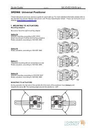
Screw positioner to housing of attachment kit. With the<br />
linear cam and the inverse equal percentage cam check<br />
whether mark 25 points to the center of the cam<br />
follower 19 (see Fig. 15); adjust if necessary.<br />
With the equal percentage cam check whether the cam<br />
follower lies directly ahead of the start of the cam lobe;<br />
adjust if necessary.<br />
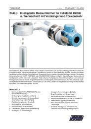
g) Final mounting of feedback lever 9 on shaft of<br />
positioner is performed at a stroke of 0 %, i.e. a rotation<br />
angle of 0°. First loosen 5 mm A/F Allen screw 15 of<br />
feedback lever 9 through hole 29 (see Fig. 19), then<br />
press stroke<br />
factor lever 31 against stop screw 30 (see page 23)<br />
and tighten Allen screw 15 firmly.<br />
h) With single-acting actuators connect positioner output<br />
y1 to actuator; with double-acting actuators connect y1<br />
and y2 to actuator.<br />
Connect chamber in which pressure is to built up with<br />
an increasing input signal to y1.<br />
i) Connect command variable w (input, 4-20 mA).<br />
k) Connect supply air of min. 1.4 bar to max. 6 bar but do<br />
not exceed the maximum permissible operating pressure<br />
of the actuator.<br />
29<br />
Fig. 19: Tightening feedback lever<br />
Note !<br />
If actuator moves to an end position, the mounting position<br />
of cam does not coincide with the direction of rotation of the<br />
actuator. In this case install the cam 24 in the reverse<br />
position.<br />
I) Attach pointer 27 on the headed screw 28 in such a<br />
manner that 0° is indicated when the rotary actuator is<br />
in its starting position (w = 0).<br />
m) Attach the transparent cover plate.<br />
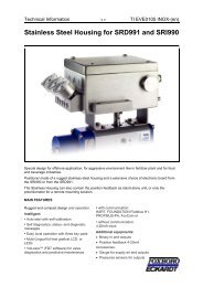
2.3.3 Reversing direction of rotation<br />
Single-acting actuator:<br />
move changeover plate 50 (see page 23) to ‘U" setting and<br />
reverse cam 24 .<br />
Double-acting actuators:<br />
exchange positioner outputs (see Fig. 16) and reverse cam.<br />
The changeover plate 50 (see page 23) remains in ‘N"<br />
setting.<br />
28 24 50 26<br />
9 27 30<br />
Fig. 20: Attachment kit for rotary movement and positioner<br />
31