SRI983 Electro-Pneumatic Positioner - explosion ... - Foxboro Eckardt
SRI983 Electro-Pneumatic Positioner - explosion ... - Foxboro Eckardt
SRI983 Electro-Pneumatic Positioner - explosion ... - Foxboro Eckardt

Create successful ePaper yourself
Turn your PDF publications into a flip-book with our unique Google optimized e-Paper software.
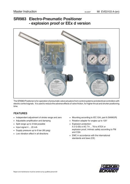
Master Instruction 04.2007 MI EVE0103 A-(en)<br />
<strong>SRI983</strong> <strong>Electro</strong>-<strong>Pneumatic</strong> <strong>Positioner</strong><br />
- <strong>explosion</strong> proof or EEx d version<br />
The <strong>SRI983</strong> <strong>Positioner</strong> is for operation of pneumatic valve actuators from control systems and electrical controllers with<br />
electric control signals. It is used to reduce the adverse effects of valve friction, for higher thrust and shorter positioning<br />
time.<br />
FEATURES<br />
• Independent adjustment of stroke range and zero<br />
• Adjustable amplification and damping<br />
• Split range up to 3-fold possible<br />
• Input signal 4 ... 20 mA<br />
• Supply pressure up to 6 bar (90 psig)<br />
• Low vibration effect in all directions<br />
Repair and maintenance must be carried out by qualified personnel!<br />
• Mounting according to IEC 534, part 6 (NAMUR)<br />
• Rotation adapter for angles up to 120°<br />
• Explosion protection:<br />
II 2 G EEx d IIC T4 ... T6 to ATEX or<br />
<strong>explosion</strong> proof, intrinsic safety according to FM<br />
and CSA<br />
• EMC in accordance with the international<br />
standards and laws (CE)
2 <strong>SRI983</strong> MI EVE0103 A-(en)<br />
CONTENTS<br />
CHP. CONTENTS PAGE<br />
1 GENERAL.............................3<br />
1.1 Identification ............................3<br />
1.2 Additional equipment. .....................3<br />
1.3 Function...............................4<br />
2 MOUNTING............................5<br />
2.1 Dimensions. ............................5<br />
2.2 Attachmentkitfordiaphragmactuators.....6<br />
2.2.1 Dimensions. ............................6<br />
2.2.2 Determination of mounting side ..............7<br />
2.2.3 Attachment to diaphragm actuators ...........7<br />
2.3 Attachmentkitforrotaryactuators.........8<br />
2.3.1 Dimensions. ............................8<br />
2.3.2 Attachmenttorotaryactuators...............9<br />
2.3.3 Reversingdirectionofrotation..............10<br />
2.4 Manual bypass switch ....................11<br />
3 ELECTRICAL CONNECTIONS ............11<br />
4 START-UP ...........................12<br />
4.1 Setting the gain.........................12<br />
4.2 Setting of zero point and stroke .............12<br />
4.3 Setting the damping .....................13<br />
4.4 Subdivision of input range<br />
(split-range). ...........................13<br />
4.5 Determination of rotation angle factor Uϕ .....14<br />
4.6 Determination of stroke factor UX ...........14<br />
4.6.1 Stroke factor ranges of the range springs ....14<br />
4.6.2 Characteristics of the range springs ........15<br />
5 MAINTENANCE .......................16<br />
5.1 Basic Adjustment of Single-acting<br />
<strong>Positioner</strong> (pneumatic part) ..............16<br />
5.2 Basic Adjustment of the Double-acting<br />
<strong>Positioner</strong> (pneumatic part) ...............17<br />
5.3 Cleaning the throttle ....................18<br />
5.4 Check and adjust I-p converter ............18<br />
6 TROUBLESHOOTING ..................19<br />
7 REPLACING SUBASSEMBLIES ..........19<br />
7.1 Replacing the amplifier ..................19<br />
7.2 Replacing the amplifier diaphragm<br />
in the single acting positioner .............20<br />
7.3 Replacing the amplifier diaphragm<br />
in the double acting positioner. ............21<br />
CHP. CONTENTS PAGE<br />
8 SAFETY REQUIREMENTS ...............22<br />
8.1 Accident prevention. .....................22<br />
8.2 Electricalsafety.........................22<br />
8.2.1 General requirements ....................22<br />
8.2.2 Regulations for Connection ................22<br />
8.2.3 Explosion protection .....................22<br />
8.2.4 EMVandCE...........................22<br />
PHOTOGRAPHS .......................23
MI EVE0103 A-(en) <strong>SRI983</strong> 3<br />
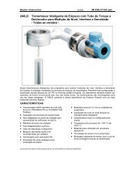
1 GENERAL<br />
The electro-pneumatic positioner is used for direct operation<br />
of pneumatic valve actuators by means of electrical<br />
controllers or control systems with an analog output signal<br />
of 4 to 20 mA or split ranges.<br />
Transmitter<br />
Valve<br />
Fig. 1: Control circuit with single-acting positioner<br />
1.1 Identification<br />
The nameplate of the positioner is located at the side wall of<br />
the housing. Nameplates are in accordance with selected<br />
model. Examples:<br />
<strong>SRI983</strong>-<br />
SER.No.<br />
Model single-acting output<br />
1.2 Additional equipment<br />
<strong>SRI983</strong><br />
Elektro-Pneumatischer Stellungsregler<br />
<strong>Electro</strong>-<strong>Pneumatic</strong> <strong>Positioner</strong><br />
A Siebe Group product<br />
Single-acting positioners are available with two built-in<br />
gauges for the indication of the input value 10 and the<br />
actuating pressure 11 (output).<br />
51<br />
Master controller <strong>Positioner</strong> Actuator<br />
0/4 - 20 mA<br />
ZULUFT max. 6 bar<br />
SUPPLY AIR max. 90 PSI<br />
ECEP<br />
STELLGRÖSSE 1<br />
OUTPUT 1<br />
max. 6 bar<br />
Fig. 4: Single-acting positioner with built-in gauges<br />
MADE IN FRANCE<br />
10<br />
11<br />
Stroke<br />
Manual bypass switch 51 for single-acting positioner only.<br />
(00) CDS 530 299 031<br />
<strong>Positioner</strong> and pneumatic actuator form a control loop with<br />
the command variable ws (output signal y of the master<br />
controller), the correcting variable ys and the stroke position<br />
xs of the actuator.<br />
In this manner disturbing influences such as gland friction<br />
and medium forces within the valve are compensated by<br />
the positioner.<br />
In addition, the positioning force of the actuator can significantly<br />
be increased by an output pressure of max. 6 bar.<br />
The electro-pneumatic positioner can be mounted on both<br />
diaphragm actuators and rotary actuators.<br />
For spring loaded actuators a single-acting positioner is<br />
used, whilst for actuators without spring loading a doubleacting<br />
positioner is used.<br />
The double-acting positioner operates with two opposing<br />
control pressures.<br />
<strong>SRI983</strong>-<br />
SER.No.<br />
STELLGRÖSSE 2<br />
OUTPUT 2<br />
Model double-acting output<br />
<strong>SRI983</strong><br />
Elektro-Pneumatischer Stellungsregler<br />
<strong>Electro</strong>-<strong>Pneumatic</strong> <strong>Positioner</strong><br />
A Siebe Group product<br />
ZULUFT max. 6 bar<br />
SUPPLY AIR max. 90 PSI<br />
ECEP<br />
STELLGRÖSSE 1<br />
OUTPUT 1<br />
MADE IN FRANCE<br />
For attachment to rotary actuators and rotary armatures an<br />
attachment-kit for rotary movement (Code EBZG-PN, -NN,<br />
-JN, -ZN, -RN) is required.<br />
Fig. 5: Housing of the attachment kit<br />
for rotary movements<br />
By means of a total of five range springs the positioner can<br />
be matched to nearly all operating situations, such as up to<br />
4-way (or with 4 to 20 mA up to 3-way) range subdivision,<br />
very high and very short strokes and angles of rotation or<br />
special cams. A standard range spring 420 494 019 is installed.<br />
Other range springs are available (see pages 14<br />
and 15).<br />
(00) CDS 530 299 049
4 <strong>SRI983</strong> MI EVE0103 A-(en)<br />
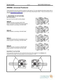
1.3 Function<br />
The positioner operates according to the force comparison<br />
principle:<br />
The input current signal w flows through coil 93, which<br />
magnetizes the magnetic system 94 . The resulting<br />
magnetic field in gap 95 enforces a permanent magnet 96<br />
proportional to input current.<br />
Magnet 96 forms the rotating system together with impact<br />
plate 97 . Impact plate 97 more or less covers nozzle 98<br />
whereby the dynamic pressure at nozzle 98 pursues a<br />
restorable force equalizing the force at magnet 96 in<br />
balance. Nozzle 98 is supplied with air via throttle 92 from<br />
output pressure w’ of the amplifier 99 driven by the change<br />
in pressure ahead of nozzle 98 .<br />
At the same time the pressure signal w’ is passed to the<br />
input diaphragm 70. The stroke of the input diaphragm is<br />
transferred to the flapper lever 54. The resultant change in<br />
the distance between the nozzle 36 and the flapper 37<br />
alters the back pressure at the nozzle. This pressure acts<br />
in a single-acting positioner on an amplifier 40. Its output<br />
pressure y results in a stroke movement of diaphragm actuator<br />
with spring resetting (see Fig. 6).<br />
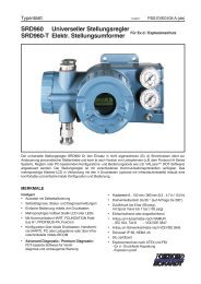
In the double-acting positioner this pressure acts on a<br />
double-acting amplifier 41 , where opposed output pressures<br />
y1 and y2 cause a stroke movement in the diaphragm<br />
actuator without spring resetting (see Fig. 7).<br />
The stroke movement is tapped at the actuator spindle 16<br />
of the feedback lever 9 and transferred to the stroke factor<br />
lever 31. The stroke factor lever 31 and the flapper lever 54<br />
are connected by the range spring 34 .<br />
Equilibrium of forces is set at the flapper lever 54 if the<br />
torque produced at the input diaphragm 70 is equal to the<br />
torque reaction of the range spring 34 produced by the<br />
stroke setting. Thus an actuator setting proportional to the<br />
signal input is retained constantly.<br />
A dynamic adaption to the actuator (sensitivity, stability) can<br />
be accomplished by the throttling screw 42 and the damping<br />
throttles 44 , 44 and 45 in the double-acting positioner.<br />
The stroke range and zero point are set via the zero screw<br />
32 and the stroke factor screw 33 .<br />
A rising or falling actuator pressure at rising input signal is<br />
set in the single-acting positioner by means of the changeover<br />
plate 50 .<br />
98<br />
92<br />
99<br />
Zuluft /<br />
Supply air<br />
16<br />
70<br />
54<br />
9<br />
34<br />
36<br />
37<br />
50<br />
31<br />
Zuluft /<br />
Supply air<br />
Fig. 6: Single-acting electro-pneumatic positioner<br />
98<br />
92<br />
99<br />
16<br />
Zuluft /<br />
Supply air<br />
97 96 95 94 93<br />
97 96 95 94 93<br />
54<br />
9<br />
34<br />
36<br />
37<br />
31<br />
70<br />
Fig. 7: Double-acting electro-pneumatic positioner<br />
44<br />
40<br />
42<br />
32<br />
33<br />
44<br />
45<br />
41<br />
Zuluft /<br />
Supply air<br />
42<br />
32<br />
33
MI EVE0103 A-(en) <strong>SRI983</strong> 5<br />
2 MOUNTING<br />
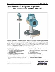
2.1 Dimensions<br />
4<br />
100<br />
3.94<br />
17<br />
.67<br />
72<br />
2.83<br />
8,8<br />
.35<br />
113,5<br />
4.47<br />
58 (93*)<br />
2.28 (3.66*)<br />
11<br />
.43<br />
106,5<br />
140 4.19<br />
5.51<br />
74,5<br />
2.93<br />
mm<br />
in<br />
182<br />
7.17<br />
47,5<br />
1.87<br />
17<br />
.67<br />
105<br />
4.13<br />
62,5<br />
2.46<br />
5 1 6 7 8 9<br />
2<br />
3<br />
Front view ** Code M, N<br />
Code L<br />
10 11<br />
1<br />
1 Electrical connection, cable gland<br />
2 Terminals (+/–) for signal input<br />
3 Earth connection<br />
4 <strong>Pneumatic</strong> connection to the rear<br />
(for attachment to diaphragm actuators)<br />
5 <strong>Pneumatic</strong> connection downwards<br />
(for attachment to rotary actuators)<br />
6 Output II<br />
(only on double-acting positioners)<br />
7 Supply air<br />
8 Output I<br />
9 Feedback lever<br />
10 Gauge for internal I/P output (w)<br />
11 Gauge for output (y)<br />
* Dimension at model with built-in gauges<br />
** I/P converter cover removed
6 <strong>SRI983</strong> MI EVE0103 A-(en)<br />
2.2 ATTACHMENT KIT FOR DIAPHRAGM ACTUATORS<br />
2.2.1 Dimensions<br />
116<br />
4.57<br />
8<br />
.31<br />
43<br />
1.69<br />
71<br />
2.80<br />
6,5<br />
.26<br />
Attachment to casting yoke<br />
according to IEC 534-6 (NAMUR)<br />
Code EBZG-GN<br />
71<br />
2.80<br />
96<br />
3.78<br />
9<br />
.35 43<br />
1.69<br />
9<br />
.35<br />
72<br />
2.83<br />
20<br />
80<br />
3.15<br />
M8<br />
17<br />
9 9<br />
54<br />
2.13<br />
176<br />
6.93<br />
49,5<br />
1.95<br />
182<br />
7.17<br />
Mounting bracket<br />
according to IEC 534-6 (NAMUR)<br />
for Code EBZG-GN, FN<br />
11<br />
.43<br />
21<br />
.83<br />
30<br />
52<br />
2.05<br />
9<br />
.35<br />
4<br />
.16<br />
.31<br />
8<br />
7,9 +0,2<br />
.31 +.01<br />
2,5<br />
.10<br />
20<br />
6<br />
.24<br />
71<br />
2.80<br />
Attachment to pillar yoke<br />
according to IEC 534-6 (NAMUR)<br />
Code EBZG-FN<br />
20 ... 35<br />
.79 ... 1.38<br />
21<br />
83<br />
3.27<br />
65<br />
2.56<br />
20<br />
91<br />
3.58<br />
10<br />
.39<br />
43<br />
1.69<br />
72<br />
2.83<br />
M6<br />
7,8 -0,05<br />
.31 -.002<br />
17<br />
54<br />
2.13<br />
Feedback lever<br />
Code EBZG-AN, -FN, -GN<br />
Code EBZG-BN (extended version)<br />
14<br />
.55<br />
10<br />
.39<br />
mm<br />
in<br />
Corrier bolt<br />
for attachment to valve stem<br />
20<br />
.78<br />
9 14 15<br />
16
MI EVE0103 A-(en) <strong>SRI983</strong> 7<br />
2.2.2 Determination of mounting side<br />
Single-acting diaphragm actuators<br />
Check whether the actuator is in the safety position required<br />
by the process (Does the actuator open or close with<br />
spring force?).<br />
The mounting side is selected from the table below in accordance<br />
with the direction of action and the required direction<br />
of movement of the spindle for an increasing input signal.<br />
Actuator closes<br />
with spring force<br />
Changeover<br />
plate setting<br />
Actuator opens Changeover<br />
with spring force plate setting<br />
The arrow indicates the direction of movement of the spindle<br />
at increasing input signal.<br />
The direction of action of the input signal can be set on the<br />
changeover plate 50 (see page 23):<br />
N= Normal direction of action (increasing input signal produces<br />
increasing control pressure to the actuator)<br />
U= Reverse direction of action (increasing input signal produces<br />
decreasing control pressure to the actuator)<br />
Double-acting diaphragm actuators<br />
For double-acting positioners the changeover plate 50 always<br />
stays in the “N” setting. The assignment of the input<br />
signal to the direction of movement of the actuator spindle<br />
is determined by the selection of the mounting side of the<br />
positioner and the piping of the positioner outputs to the<br />
actuator:<br />
If the actuator spindle is to ascend with an increasing input<br />
signal, output y1 is connected at top of the actuator and<br />
output y2 is connected at bottom.<br />
The positioner is mounted at the right-hand side.<br />
If the actuator spindle is to retract with an increasing input<br />
signal, output y1 is connected at bottom and output y2 at top<br />
of the actuator.<br />
The positioner is mounted at the left-hand side.<br />
Changeover<br />
plate setting<br />
The arrow indicates the direction of movement of the<br />
spindle with an increasing input signal.<br />
Changeover<br />
plate setting<br />
2.2.3 Attachment to diaphragm actuators<br />
Attachment of the positioner is made using the attach-ment<br />
kit for diaphragm actuators according to DIN IEC 534-6 at<br />
right or left-hand side of the actuator.<br />
a) Screw the carrier bolt 16 into actuator coupling (see<br />
Fig. 12).<br />
b) Screw mounting bracket 20 flush with the positioner<br />
with two M 6 socket head cap screws (5 mm A/F).<br />
c) Fasten positioner with mounting bracket 20 to the<br />
diaphragm actuator.<br />
For FOXBORO ECKARDT diaphragm actuators with<br />
cast yokes:<br />
fasten mounting bracket 20 with screw M 8 to the<br />
threaded hole in the cast yoke.<br />
This ensures that the feedback lever 9 is horizontal at<br />
50 % stroke.<br />
For diaphragm actuators with pillars:<br />
fasten mounting bracket 20 with two U-bolts 21 to the<br />
pillar in such a manner that feedback lever 9 which is<br />
loosely attached to shaft 17 of positioner and carrier<br />
bolt 16 , is horizontal at 50 % stroke.<br />
d) Setactuatortoa0%strokeposition.<br />
Attach feedback lever 9 to shaft 17 of the positioner<br />
and carrier bolt 16 in such a manner that compensating<br />
spring 14 is above carrier bolt 16 when the mounting<br />
side is on the right, or below carrier bolt 16 when the<br />
mounting side is on left.<br />
Align and lock carrier bolt.<br />
e) Press stroke factor lever 31 against stop screw 30 and<br />
create a frictional connection between feedback lever 9<br />
and shaft 17 of positioner by tightening hexagon cap<br />
screw 15 (10 mm A/F) of feedback lever.<br />
f) Connect positioner output y1 to single-acting diaphragm<br />
actuators and connect outputs y1 and y2 to doubleacting<br />
diaphragm actuators.<br />
g) Set up electrical connections.<br />
h) Connect supply air of min. 1.4 bar to max. 6 bar, but no<br />
more than the maximum permissible operating pressure<br />
of the diaphragm actuator.<br />
i) Fasten housing cover in such a way that air vent of<br />
attached device faces downwards<br />
(see Mark ‘M‘ in Fig. 12).<br />
M<br />
9 16 14<br />
Fig. 12: Actuator with pillars (mounting side left)
8 <strong>SRI983</strong> MI EVE0103 A-(en)<br />
2.3 ATTACHMENT KIT FOR ROTARY ACTUATORS<br />
2.3.1 Dimensions<br />
15 0,2<br />
.59 .01<br />
With shaft<br />
(according to VDI/VDE 3845)<br />
Code EBZG-ZN<br />
12<br />
.47<br />
4,5<br />
.18<br />
4<br />
.16<br />
Detail Z<br />
mm<br />
14<br />
.55<br />
13,5<br />
.53<br />
8<br />
.31<br />
6<br />
.53<br />
143,5<br />
5.65<br />
Without flange<br />
Code EBZG-NN, -PN<br />
Detail Y<br />
16<br />
.63<br />
11<br />
.43<br />
M6<br />
With flange<br />
Code EBZG-JN<br />
143,5<br />
5.65<br />
1,2<br />
.05<br />
183,5<br />
7.22<br />
28+0,5<br />
1.10+.02<br />
14 ... 15,5<br />
.55 ... .61<br />
30<br />
1.18<br />
30<br />
1.18<br />
70<br />
2.76<br />
5<br />
.20<br />
6<br />
47 .24<br />
1.85<br />
in 54<br />
10<br />
2.13<br />
63<br />
2.48<br />
86<br />
3.39<br />
3<br />
.12<br />
Adaption of the actuator drive shaft end<br />
and correct axial location by client !<br />
.39<br />
6,5<br />
/<br />
.26<br />
0,2<br />
.01<br />
12<br />
.47<br />
12<br />
.47<br />
16H8<br />
.63<br />
14 - 6<br />
.55 - .24<br />
75<br />
2.95<br />
60 0,2<br />
2.36 .01<br />
Housing dimensions<br />
Attachment kit with shaft Code EBZG-ZN<br />
resp. without flange Code EBZG-NN<br />
10<br />
.39<br />
43<br />
1.69<br />
50<br />
1.97<br />
43<br />
1.69<br />
45 0,2<br />
1.77 .01<br />
167<br />
6.57<br />
167<br />
6.57<br />
.26 12<br />
50<br />
1.97 6,5<br />
95<br />
3.74<br />
M6<br />
95<br />
3.74<br />
22<br />
.87<br />
64<br />
2.52<br />
Housing dimensions<br />
Attachment kit without flange<br />
Code EBZG-PN<br />
64<br />
2.52<br />
Rotation angle max 120˚; torque requirement 14 Nm<br />
.47<br />
99<br />
3.90<br />
99<br />
3.90
MI EVE0103 A-(en) <strong>SRI983</strong> 9<br />
2.3.2 Attachment to rotary actuators<br />
For attachment of the positioner to rotary actuators or rotary<br />
armatures an attachment kit is required. The linear cam<br />
enables sensing of rotation angles up to 120°, wheras the<br />
equal percentage and the inverse equal percentage cams<br />
sense rotation angles up to 90° (linear characteristic between<br />
70° and 90°).<br />
Attachment<br />
a) Remove the transparent cover plate from the housing<br />
26 of the attachment kit.<br />
b) Mount the housing of the attachment kit on rotary actuator<br />
or armature; use mounting hardware supplied by<br />
the actuator manufacturer if necessary.<br />
Fig.14: Rotary actuator with attachment kit<br />
c) Move actuator into the desired starting position<br />
(rotation angle = 0°).<br />
d) Mount cam 24 in accordance with the direction of rotation<br />
of the actuator (see Fig. 15). The linear cam is fastened<br />
to the actuator drive shaft in such a manner that<br />
the dimension x or y (Fig. 16) amounts 2 mm, whereas<br />
in case of equal percentage cam the dimension x is<br />
approx. 17.5 mm, and the dimension y is approx. 21.5<br />
mm. In case of inverse equal percentage cam the<br />
dimension x is approx. 18 mm, and the dimension y is<br />
approx. 23 mm.<br />
When employing equal percentage and the inverse<br />
equal percentage cams, the range spring 420 493 013<br />
(included in spring set FESG-FN) must be installed in<br />
the positioner.<br />
A =<br />
B =<br />
26<br />
Mounting position<br />
for actuator<br />
rotation<br />
Mounting position<br />
for actuator<br />
rotation<br />
24<br />
A B<br />
% %<br />
equal percentage<br />
Fig.15: Mounting position of the cams<br />
A<br />
A<br />
24<br />
19 25<br />
linear<br />
24<br />
B<br />
B<br />
19 25<br />
invers equal percentage<br />
Zuluft /<br />
Supply air<br />
Fig.16: Rotary actuator with attachment kit for rotary<br />
movement and double-acting positioner<br />
Fig. 17: Attaching feedback lever to the positioner<br />
e) Fasten feedback lever 9 for the rotary actuator onto<br />
shaft 17 of positioner as shown in Fig. 17.<br />
f) Mount positioner on housing 26 of attachment kit.<br />
Attach spring 18 to feedback lever 9 and cam follower<br />
19 against cam (see Fig. 18).<br />
9<br />
26<br />
15<br />
17<br />
X<br />
Fig.18: Alignment of cam<br />
24<br />
Zuluft /<br />
Supply air<br />
9<br />
19<br />
18
10 <strong>SRI983</strong> MI EVE0103 A-(en)<br />
Screw positioner to housing of attachment kit. With the<br />
linear cam and the inverse equal percentage cam check<br />
whether mark 25 points to the center of the cam<br />
follower 19 (see Fig. 15); adjust if necessary.<br />
With the equal percentage cam check whether the cam<br />
follower lies directly ahead of the start of the cam lobe;<br />
adjust if necessary.<br />
g) Final mounting of feedback lever 9 on shaft of<br />
positioner is performed at a stroke of 0 %, i.e. a rotation<br />
angle of 0°. First loosen 5 mm A/F Allen screw 15 of<br />
feedback lever 9 through hole 29 (see Fig. 19), then<br />
press stroke<br />
factor lever 31 against stop screw 30 (see page 23)<br />
and tighten Allen screw 15 firmly.<br />
h) With single-acting actuators connect positioner output<br />
y1 to actuator; with double-acting actuators connect y1<br />
and y2 to actuator.<br />
Connect chamber in which pressure is to built up with<br />
an increasing input signal to y1.<br />
i) Connect command variable w (input, 4-20 mA).<br />
k) Connect supply air of min. 1.4 bar to max. 6 bar but do<br />
not exceed the maximum permissible operating pressure<br />
of the actuator.<br />
29<br />
Fig. 19: Tightening feedback lever<br />
Note !<br />
If actuator moves to an end position, the mounting position<br />
of cam does not coincide with the direction of rotation of the<br />
actuator. In this case install the cam 24 in the reverse<br />
position.<br />
I) Attach pointer 27 on the headed screw 28 in such a<br />
manner that 0° is indicated when the rotary actuator is<br />
in its starting position (w = 0).<br />
m) Attach the transparent cover plate.<br />
2.3.3 Reversing direction of rotation<br />
Single-acting actuator:<br />
move changeover plate 50 (see page 23) to ‘U" setting and<br />
reverse cam 24 .<br />
Double-acting actuators:<br />
exchange positioner outputs (see Fig. 16) and reverse cam.<br />
The changeover plate 50 (see page 23) remains in ‘N"<br />
setting.<br />
28 24 50 26<br />
9 27 30<br />
Fig. 20: Attachment kit for rotary movement and positioner<br />
31
MI EVE0103 A-(en) <strong>SRI983</strong> 11<br />
2.4 Manual bypass switch<br />
The single acting pneumatic positioner can also be supplied<br />
with a bypass switch 51 (see page 23) if it is intendet for<br />
use with actuators with a signal range of 0.2 ... 1 bar.<br />
In the “ON” position the actuating signal of the master controller<br />
is supplied via the positioner; in the “OFF” position it<br />
is connected direct to the actuator.<br />
w<br />
x<br />
EIN<br />
51 ON<br />
Fig. 21: Bypass circuit<br />
Note!<br />
The bypass switch may only be operated in the normal<br />
direction of action (changeover plate 50 in position “N”, see<br />
page 23), i. e. when the “OFF” position is set.<br />
It should also be noted that the stored pressure in the actuator<br />
chamber may have a feedback effect on the preceding<br />
controllers when the “OFF” position is set, and could<br />
overload them.<br />
The pressure in the actuator chamber should therefore be<br />
reduced accordingly before the changeover. The spring<br />
range of the actuator should not exceed the maximum signal<br />
value of the master controller, in order to ensure that the<br />
valve can open and close fully.<br />
w<br />
x<br />
51<br />
AUS<br />
OFF<br />
3 ELECTRICAL CONNECTIONS<br />
During installation, the installation requirements by DIN<br />
VDE 0100 and/or DIN VDE 0800, as well as locally applicable<br />
requirements must be observed.<br />
In addition, the requirements of VDE 0165 must be observed<br />
for systems associated with hazardous areas.<br />
Further important instructions are contained in page 22<br />
(safety requirements, <strong>explosion</strong> protection).<br />
If an earth connection or potential equalization are required,<br />
connect to earth connection 3 .<br />
The units must be operated in a stationary position.<br />
The line (cable) is guided through a screwed gland. This is<br />
suitable for line diameters of 6 to 12 mm.<br />
The electrical connections for the command variable w is<br />
made at the + and – screw terminals 2 , which are suitable<br />
for wire cross-sections of up to 2.5 mm² (see Fig. 22).<br />
Fig. 22: Electrical connections 2 and earth connection 3<br />
2<br />
3
12 <strong>SRI983</strong> MI EVE0103 A-(en)<br />
4 START-UP<br />
Before commissioning electro-pneumatic positioners must<br />
be matched to the stroke and rotation angle of the actuator<br />
and to the input signal range.<br />
The instruments can be connected to the 4 to 20 mA input<br />
signals or split ranges.<br />
The supply air connected should be min. 1.4 bar and max.<br />
6 bar, but should not exceed the maximum operating pressure<br />
of the diaphragm actuator.<br />
4.1 Setting the gain<br />
(see page 23)<br />
The gain and thus the sensitivity of the positioner are set by<br />
means of the throttling screw 42 . The throttling screw is<br />
screwed in all the way in the factory, i.e. it is set to maximum<br />
gain. This gain varies with the supply air pressure, as<br />
shown in the following table:<br />
Supply air<br />
Single-acting<br />
positioner<br />
max. gain<br />
Double-acting<br />
positioner<br />
1.4 bar approx. 150 approx. 100<br />
4 bar approx. 90 approx. 150<br />
6 bar approx. 60 approx. 180<br />
The linear gain is indicated. These values are based on the<br />
built-in range spring 420 494 019.<br />
From this basic setting the gain can be matched to the dynamic<br />
requirements of the control system (counter-clockwise<br />
rotation of the throttling screw 42 results in less gain).<br />
Note :<br />
The zero point must be adjusted following each change of<br />
gain.<br />
In order to ensure reliable pressure reduction in the actuator,<br />
the throttling screw 42 should not be opened beyond<br />
¼ turn at 6 bar. A limiting screw 43 is therefore incorporated.<br />
The basic setting at the factory permits a maximum opening<br />
of the throttling screw 42 of approx. 1 turn.<br />
4.2 Setting of zero point and stroke<br />
(see page 23)<br />
Before commencing settings press the flapper lever 35 several<br />
times alternately to the left and right in order to align<br />
the flappers correctly.<br />
a) Set the minimum value of the command variable w<br />
(start of stroke).<br />
b) Turn zero screw 32 until actuator just begins to move<br />
from its end position.<br />
c) Set maximum value of the command variable w (end of<br />
stroke).<br />
d) Turn the stroke factor screw 33 until actuator precisely<br />
reaches its end position:<br />
Right turn: decrease of travel<br />
Left turn: increase of travel<br />
Recheck zero and stroke settings.<br />
Note:<br />
When stop screw 30 is correctly positioned and feedback<br />
lever is correctly mounted, there is no interaction between<br />
the adjustments of zero and stroke.<br />
If the stroke cannot be adjusted with the installed spring, the<br />
correct spring can be approximately determined in accordance<br />
with the following criteria:<br />
Upper end position requires softer spring<br />
with higher number of turns<br />
(for large strokes and “split-range”)<br />
corresponds to<br />
curve (1-5) b<br />
(see page 15)<br />
Stroke range of built-in spring<br />
corresponds to<br />
curve (1-5) a<br />
Lower end position requires harder spring<br />
with fewer turns<br />
(for shorter strokes and equal percentage cam)<br />
There are 5 differently rated springs available for matching<br />
the stroke and input signal range.<br />
The particular spring 34 required can be determined precisely<br />
via stroke factor Ux.
MI EVE0103 A-(en) <strong>SRI983</strong> 13<br />
4.3 Setting the damping<br />
(see page 23)<br />
The air output capacity of the positioner can be reduced by<br />
means of the damping throttle 44 .<br />
Double-acting positioners are equipped with a damping<br />
throttle 44 for correcting the variable y1 and a damping<br />
throttle 45 for correcting the variable y2 .<br />
In its normal setting the damping throttle is approximately<br />
flush with the amplifier housing.<br />
The air output capacity is reduced by a factor of approx. 2.5<br />
when the damping throttle is turned completely in.<br />
A reduction of the air output capacity should only be done<br />
for very small actuator volumes since the control system<br />
would otherwise be too slow.<br />
4.4 Subdivision of input range<br />
(split-range)<br />
If several actuators are to be controlled by the same command<br />
variable and the complete stroke is to be executed in<br />
only one specific subrange of this command variable at a<br />
time, a positioner, the zero point and stroke range of which<br />
must be set to the desired sub-range of the command variable,<br />
must be provided for each actuator.<br />
For actuation of several positioners by a master controller<br />
the positioners are connected in series.<br />
Fig. 24: Example of 2-way subdivision<br />
It should be noted that the permissible load of the controller<br />
may not be exceeded.<br />
The input resistance of the positioner at 20 °C is approx.<br />
200 ohms.<br />
Selection of the correct range spring can be made in<br />
accordance with the stroke factor range or the graph of the<br />
range springs (see page 15).<br />
If the zero point has to be increased by more than 10 mA<br />
in case of multiple subdivision the adjustment must be<br />
made as follows: (see page 23)<br />
a) Shut off supply air.<br />
b) Remove tension from range spring 34 by turning zero<br />
screw 32 .<br />
c) Loosen hexagon cap screw (A/F 10) of feedback lever<br />
and turn stroke factor lever 31 away from stop screw<br />
30 . This applies pretension to range spring 34 .Inthis<br />
position retighten hexagon cap screw of feedback lever.<br />
34<br />
30<br />
Fig. 25: Pretension of the range spring<br />
d) Connect supply air.<br />
e) Set the minimum value of command variable w (start of<br />
stroke).<br />
f) Turn zero screw 32 , until the actuator begins to move<br />
from its end position. If this is not possible, the pretension<br />
of the range spring must be increased as described<br />
in c).<br />
g) Set maximum value of command variable w (end of<br />
stroke).<br />
h) Turn stroke factor screw 33 until the actuator precisely<br />
reaches its end position.<br />
Note !<br />
With this setting the zero point and stroke range are mutually<br />
dependent. Settings e) to h) must therefore be repeated<br />
as often as necessary until both settings are correct.<br />
Furthermore it should be noted that the deflection of the<br />
stroke factor lever 31 from the starting position may not exceed<br />
a maximum of 39°, since the stroke factor lever might<br />
otherwise hit the housing cover before reaching its end<br />
value.<br />
31<br />
32<br />
33
14 <strong>SRI983</strong> MI EVE0103 A-(en)<br />
4.5 Determination of rotation angle factor Uϕ<br />
In conjunction with the attachment kit for rotary actuators<br />
(Code EBZG-PN, -MN, -JN, -ZN, -RN) the rotation angle<br />
factor Uϕ can be determined as follows:<br />
ϕ<br />
Rotation angle<br />
Uϕ =<br />
=<br />
∆ w Input signal range [ mA ]<br />
The rotation angle factors Uϕ of the individual range springs<br />
are stated in the following table.<br />
The rotation angles are also taken into account in the graph<br />
of the range springs (see page 15).<br />
4.6 Determination of stroke factor UX The stroke factor Ux is the ratio of the entire range of the<br />
output variable (stroke x) to the entire range of the input<br />
variable (command variable w).<br />
For FOXBORO ECKARDT diaphragm actuators PA-200 to<br />
PA700/702 :<br />
x<br />
Stroke in mm<br />
Ux =<br />
=<br />
∆ w Input signal range in mA<br />
Range spring Cam 1)<br />
Ident No. old ID Colour<br />
1 420 493 013 FES 627/1 yellow<br />
2 420 494 019 FES 628/1 green<br />
3 502 558 017 FES 612/1 - without -<br />
4 420 496 011 FES 715/1 gray<br />
5 420 495 014 FES 629/1 blue<br />
linear<br />
For FOXBORO ECKARDT diaphragm actuators 1500 cm²<br />
and actuators of other manufacturers (Io = 117.5 mm 1) ):<br />
Ux =<br />
x<br />
Io<br />
×<br />
∆ w Is<br />
Is = Feedback lever length in mm (for FOXBORO<br />
ECKARDT actuator 1500 cm²: Is = 122.5 mm)<br />
The stroke factor can be used to determine for each application<br />
whether or with which spring the desired setting can<br />
be made.<br />
Five different range springs are available for matching to<br />
the stroke and input signal range.<br />
4.6.1 Stroke factor ranges of the range springs<br />
ThestrokefactorUx determined as described above should<br />
lie within the ranges of the respective range springs indicated<br />
in the following table, as close as possible to the lower<br />
value.<br />
Equal perc. and<br />
inverse<br />
equal perc.<br />
max. 120° max. 90°<br />
1.7 ... 4.7<br />
(max. 7)<br />
3.5 ... 9.5<br />
(max. 14)<br />
5.8 ... 14.5<br />
(max. 21.75)<br />
8.4 ... 21.5<br />
(max. 32.75)<br />
11.5 ... 27.5<br />
(max. 41.5)<br />
2.4 ... 8<br />
(max. 10)<br />
5 ... 15<br />
(max. 20)<br />
8.2 ... 24<br />
(max. 28)<br />
12 ... 35<br />
(max. 43)<br />
-<br />
Stroke factor ranges<br />
Stroke factor<br />
Ux<br />
mm<br />
mA<br />
0.4 ... 1.2<br />
(max. 1,7)<br />
0.85 ... 2.3<br />
(max. 3.35)<br />
1.4 ... 3.5<br />
(max. 5.25)<br />
2.0 ... 5.5<br />
(max. 7.9)<br />
2.75 ... 7.0<br />
(max. 10)<br />
Stroke<br />
range 2)<br />
mm<br />
Remarks<br />
8 ... 34 2)<br />
17 ... 68 built-in<br />
28 ... 105 2)<br />
40 ... 158 3)<br />
55 ... 200 3)<br />
1) For equal percentage and inverse equal percentage cams the rotation angle factors are a function of their corresponding rotation angles.<br />
2) Included in FESG-FN (Id No. 420 496 011)<br />
2)<br />
2)
MI EVE0103 A-(en) <strong>SRI983</strong> 15<br />
4.6.2 Characteristics of the range springs<br />
The stroke xo is based on the FOXBORO ECKARDT<br />
standard feedback lever Io=117.5 mm.<br />
ϕ<br />
[∠°]<br />
lin<br />
120<br />
90<br />
60<br />
30<br />
%<br />
90<br />
70<br />
30<br />
10<br />
0 0<br />
x0 [mm]<br />
50<br />
40<br />
30<br />
20<br />
10<br />
Stroke<br />
Is min. =<br />
72<br />
2.83<br />
Lifting up of zero point for 4...20 mA and split range<br />
1a, 2a, 3a, 4a, 5a = stroke starting of the respective spring<br />
1b, 2b, 3b, 4b, 5b = max. stroke<br />
Io =<br />
117,5<br />
4.62<br />
Is max. =<br />
142<br />
5.59<br />
Fig. 26: Feedback lever<br />
If another length (ls) is used, the actual stroke xs must be<br />
converted to stroke xo<br />
117.5 ⋅ xs<br />
xo =<br />
[mm]<br />
Is<br />
Selection of measuring spring and setting of<br />
measuring span<br />
Determination of suitable spring for split range:<br />
a) Enter desired setpoint value w for travel start in the<br />
diagram field.<br />
b) Determine xo if Is unequal 117.5 mm.<br />
c) Enter intersection w/xo .<br />
d) Connect points determined at a) and c). This results in a<br />
straight line.<br />
e) If the straight line does not run through the origin, move<br />
this parallel here.<br />
f) Use the spring the characteristic line (a) of which is<br />
located directly below the presently determined<br />
characteristic line.<br />
Example (shown in graph)<br />
Split range operation<br />
Valve 1:<br />
w = 0 ... 10 mA<br />
xs = 30 mm (stroke range)<br />
Is = 140 mm<br />
xo =<br />
117.5 ⋅ 30<br />
140<br />
=25.2mm<br />
Intersection w = 10 mA with xo =25.2mm→S1 Selected: Spring 4 (FES 715/1) because the characteristic<br />
curve based on the beginning of the determined straight<br />
line located directly below.<br />
Valve 2:<br />
w = 10 ... 20 mA<br />
xs = 50 mm (stroke range)<br />
Is = 140 mm<br />
xo =<br />
117.5 ⋅ 50<br />
140<br />
=42mm<br />
Intersection w = 20 mA with xo =42mm→S2 Selected: Spring 5 (FES 629/1) because the characteristic<br />
curve based on the beginning of the determined straight<br />
line located directly below.<br />
5b 4b 3b 2b<br />
0<br />
Setpoint<br />
0 0.2 0.4 0.6 0.8 1 w [bar]<br />
S1<br />
5a<br />
S2<br />
4a 1b<br />
Zero elevation 1a ... 5a = minimum stroke range of each spring<br />
1b ... 5b = maximum available strokes<br />
5a<br />
3a<br />
2a<br />
1a<br />
1) I o = FOXBORO ECKARDT standard feedback effective length<br />
2) For feedback effective length I s = 117.5 mm and ∆ w=20mA<br />
3) Theoretical value
16 <strong>SRI983</strong> MI EVE0103 A-(en)<br />
5 MAINTENANCE<br />
5.1 Basic Adjustment of Single-acting<br />
<strong>Positioner</strong> (pneumatic part)<br />
Basic setting is only necessary after dismantling the device<br />
or changing modules.<br />
All the settings for adapting the positioner to the actuator<br />
are described in page 12 (start-up).<br />
The following tools are required for basic adjustment:<br />
screwdriver<br />
1 open-end spanner 7 mm A/F<br />
1 feeler 0.6 mm<br />
1 test gauge 1.6 bar<br />
1 DC signal generator<br />
The feedback lever must be detached from the shaft of<br />
positioner if adjustment is done in the attached state.<br />
For the following adjustments see page 23.<br />
a) Set changeover plate 50 to “N”.<br />
b) Turn throttling screw 42 to the right as far as possible<br />
(maximum boost).<br />
c) Unhook range spring 34 from flapper lever 35 .<br />
d) Check whether the flappers 37 are concentric with the<br />
nozzles 36 . If not, align booster 40 . The fastening<br />
screws of the booster are accessible at the rear side of<br />
the positioner.<br />
e) Push flapper lever 35 alternately to the left and right<br />
several times to align the ball-guided flappers parallel to<br />
the nozzles.<br />
f) Push flapper lever 35 to the left. By turning the hexagonal<br />
rod 38 7 mm A/F set the distance between the<br />
right-hand nozzle and the right-hand flapper to approx.<br />
0.6 mm with the aid of a feeler. Then fasten the hexagonal<br />
rod tight.<br />
g) Connect the positioner as shown in the test circuit, fig.<br />
28, preset supply air to 1.4 bar.<br />
h) Press flapper lever 35 to the left. If the output y does<br />
not rise to supply air pressure, there are leaks or the<br />
flapper is not correctly positioned (repeat ‘e’).<br />
i) Hook range spring 34 into flapper lever and preset DC<br />
signal w = 10 mA. Proceed as follows to make zero<br />
setting independent of the stroke setting:<br />
k) Press stroke factor lever 31 against stop screw 30 .<br />
I) Set a large stroke factor (approx. 2 mm in front of top<br />
stop) with stroke factor screw 33 .<br />
m) Set zero screw 32 so that the output pressure y =<br />
approx. 0.6 bar and note this value.<br />
n) Set a small stroke factor (approx. 2 mm in front of<br />
bottom stop) with the stroke factor screw 33 .<br />
The output pressure y may not change by more than<br />
±150 mbar in relation to setting m).<br />
o) The stop screw 30 should be adjusted in case of<br />
greater deviations. Repeat settings l) to n) after every<br />
adjustment of the stop screw 30 until the deviation is<br />
less than ±150 mbar.<br />
p) Secure stop screw 30 with varnish.<br />
Put changeover plate 50 back in its original position. Reinstall<br />
positioner or reattach the feedback lever to positioner<br />
shaft.<br />
See page 12 for start-up.<br />
y<br />
SRI 983<br />
Zuluft<br />
Supply air<br />
Fig. 28: Test circuit for single acting positioner<br />
+<br />
+<br />
w<br />
_<br />
_<br />
DC 10 mA
MI EVE0103 A-(en) <strong>SRI983</strong> 17<br />
5.2 Basic Adjustment of the Double-acting<br />
<strong>Positioner</strong> (pneumatic part)<br />
Basic setting is only necessary after dismantling the device<br />
or changing modules.<br />
All settings for adapting the positioner to the actuator are<br />
described in page 12 (start-up).<br />
The following tools are required for basic adjustment:<br />
screwdriver<br />
1 open-end spanner 7 mm A/F<br />
1 feeler 0.6 mm<br />
2 test gauges 6 bar<br />
1 DC signal generator<br />
The feedback lever must be detached from the shaft of the<br />
positioner if adjustment is done in the attached mode.<br />
For the following adjustments see pages and .<br />
a) Leave changeover plate 50 set to “N”.<br />
b) Turn throttling screw 42 to the right as far as possible<br />
(maximum boost).<br />
c) Unhook range spring 34 from flapper lever 35 .<br />
d) Check whether flappers 37 are concentric with nozzles<br />
36 . If not, align booster 41 . The fastening screws of the<br />
booster are accessible at the rear side of the positioner.<br />
e) Push flapper lever 35 alternately to the left and right<br />
several times to align ball-guided flappers parallel to<br />
nozzles.<br />
f) Push flapper lever 35 to the left. By turning the hexagonal<br />
rod 38 7 mm A/F set the distance between the<br />
right-hand nozzle and the right-hand flapper to approx.<br />
0.6 mm with the aid of a feeler. Then fasten hexagonal<br />
rod tight.<br />
g) Connect positioner as shown in the test circuit, fig. 29,<br />
preset supply air to 6 bar.<br />
h) Press flapper lever 35 to the right and left. The pressures<br />
y1 and y2 must change in opposition between 0<br />
and supply air pressure.<br />
i) Hook range spring 34 into flapper lever and preset DC<br />
signal w = 10 mA.<br />
k) Set zero screw 32 so that pressures y1 and y2 are<br />
equal.<br />
I) Set adjustment screw 47 so that pressures y1 and y2<br />
are set to approx. 4.2 bar (70 % of the supply air<br />
pressure). Repeat settings k) and l) alternately if<br />
necessary.<br />
m) Preset 1.4 bar supply air.<br />
Set zero screw 32 so that pressures y1 and y2 are<br />
equal. They should be approx. 0.7 bar (50 % of the<br />
supply air pressure) (check measurement only).<br />
Proceed as follows to make the zero setting indepen-dent<br />
of the stroke setting:<br />
n) Press stroke factor 31 lever against the stop screw 30 .<br />
o) Set a large stroke factor (approx. 2 mm in front of the<br />
top stop) with the stoke factor screw 33 .<br />
p) Set the zero screw 32 so that output pressures y1 and<br />
y2 are equal.<br />
r) Set a small stroke factor (approx. 2 mm in front of the<br />
bottom stop) with the stroke factor screw. The output<br />
pressures y1 and y2 may not change by more than ±150<br />
mbar in relation to setting p).<br />
s) The stop screw 30 should be adjusted in case of<br />
greater deviations. Repeat settings o) to r) after every<br />
adjustment of stop screw 30 until the deviation is less<br />
than ±150 mbar.<br />
t) Secure stop screw 30 with varnish.<br />
Reinstall the positioner or reattach the feedback lever to<br />
positioner shaft.<br />
See page 12 for start-up.<br />
SRI 983<br />
y1 y<br />
2<br />
Zuluft<br />
Supply air<br />
Fig. 29: Test circuit for double acting positioner<br />
+<br />
+<br />
w<br />
_<br />
_<br />
DC 10 mA
18 <strong>SRI983</strong> MI EVE0103 A-(en)<br />
5.3 Cleaning the throttle<br />
(see page 23)<br />
a) Remove the limiting screw 43 .<br />
b) Pull the throttling screw 42 down out of the limiting<br />
screw.<br />
c) Place the throttling screw 42 in a solvent (e. g. benzene)<br />
and blow through it carefully. It is better still to clean it in<br />
an ultrasonic bath.<br />
d) Turn the throttling screw 42 right in again as far as its<br />
stop (clockwise).<br />
e) Turn the limiting screw 43 right in as far as its stop<br />
(clockwise), then back again counterclockwise by about<br />
half a turn.<br />
f) Secure the limiting screw 43 with sealing paint.<br />
5.4 Check and adjust I-p converter<br />
An adapter is required for checking and adjusting the I-p<br />
converter which can be done by yourself as shown in Fig.<br />
32.<br />
The following tools are required:<br />
Screw driver,<br />
5 mm A/F allen keys,<br />
1 test gauge 0 to 1.4 bar,<br />
1 DC signal generator 4 to 20 mA,<br />
supply air 1.4 ± 0.1 bar.<br />
a) Remove the I-p converter 91 from connecting manifold<br />
90 (two screws M 6), connect it to the adapter Fig. 32<br />
and wire as shown in Fig. 30.<br />
b) Preset supply air 1.4 ± 0.1 bar.<br />
c) The test gauge must read 0.2 bar at current signal 0 mA.<br />
Otherwise set the adjustment screw 92 so that this<br />
value is indicated.<br />
d) Increase the current signal slowly from 4 to 20 mA. The<br />
test gauge reading must change proportionately to the<br />
current signal.<br />
Current signal Test gauge reading<br />
0mA<br />
20 mA<br />
approx. 0.2 bar<br />
approx. 1 bar<br />
e) Adjust range with potentiometer 93 .<br />
If these values are not achieved, there is a defect and the<br />
I-p converter should be replaced or the positioner returned<br />
to the manufacturer for repair.<br />
+<br />
0 ... 20 mA<br />
–<br />
Supply air<br />
1.4 +_ 0.1 bar<br />
I-p converter<br />
with<br />
adapter<br />
Fig. 30: Test circuit for I-p converter<br />
0 ... 1.4 bar<br />
Fig. 31: I-p converter, cover removed<br />
42<br />
1.65<br />
15,5<br />
0.61<br />
4,5<br />
.18<br />
92<br />
93<br />
M6<br />
hoses<br />
connection<br />
50<br />
1.96 43,5<br />
1.71<br />
Output<br />
Supply air<br />
33,5<br />
1.32<br />
M6<br />
7,5<br />
0.30<br />
8<br />
.31<br />
Fig. 32: Test adapter for I-p converter<br />
9<br />
.35<br />
17,5<br />
0.69<br />
2;<br />
countersink<br />
for O-ring<br />
4x1<br />
10<br />
.39<br />
5<br />
.19<br />
90<br />
91
MI EVE0103 A-(en) <strong>SRI983</strong> 19<br />
6 TROUBLESHOOTING<br />
Fault Possible causes Remedies<br />
Actuator does not react<br />
to the applied input signal<br />
nor to a change in the input signal.<br />
Output pressure does not reach full<br />
value<br />
7 REPLACING SUBASSEMBLIES<br />
7.1 Replacing the amplifier<br />
(see page 23)<br />
a) Remove the housing cover.<br />
b) Unhook the range spring 34 from the flapper lever 35 .<br />
c) Unscrew and remove the amplifier 40 or dual amplifier<br />
41 . The two mounting bolts are accessible from the<br />
rear of the positioner.<br />
pneumatic connections switched check connections<br />
electrical connections switched reverse electrical connections<br />
feedback lever loose tighten feedback lever<br />
<strong>Positioner</strong> mounted on the wrong side check mounting side see table section<br />
2.2.2<br />
changeover plate in the wrong position check position see table in section 2.2.2<br />
booster defective change booster (see 7.1 )<br />
I-p converter defective See note in section 5.4 and proceed<br />
accordingly<br />
supply pressure too low check supply air<br />
flappers not parallel to nozzles align flappers<br />
(see 5.1 d, e or 5.2 d, e)<br />
pre-throttle in booster blocked clean pre-throttle (see 5.3)<br />
I-p converter defective see note in section 5.4 and proceed<br />
accordingly<br />
filter in supply connection blocked change filter<br />
Actuator runs to the end position positioner mounted on wrong side check mounting side see table section<br />
2.2.2<br />
feedback lever loose tighten feedback lever<br />
pneumatic connections switched<br />
check connections<br />
(double-acting version)<br />
(see 2.2.2 or 2.3.2)<br />
Unstable behavior -<br />
boost too high reduce boost (see 4.1)<br />
positioner circuit oscillates gland friction on valve too great loosen gland slightly or renew<br />
for piston actuators:<br />
static friction on cylinder too great<br />
reduce boost (see 4.1)<br />
Stroke range cannot be set range spring unsuitable change range spring (see 4.5 and 4.6)<br />
positioner does not exhaust pressure<br />
completely<br />
check supply air (max. 6 bar)<br />
check boost (see 4.1)<br />
adjust distance between nozzle and<br />
flapper (see 5.1 e, f or 5.2 e, f)<br />
d) Install a new amplifier.<br />
Do not forget the O-rings between the amplifier and the<br />
base plate (manifold).<br />
Before tightening the mounting bolts align the amplifier<br />
in such a way that the flappers 37 are concentrically<br />
aligned with the nozzles 36 .<br />
e) Hook the range spring 34 onto the flapper lever 35 .<br />
f) Perform a basic adjustment (see 5.1 or 5.2).
20 <strong>SRI983</strong> MI EVE0103 A-(en)<br />
7.2 Replacing the amplifier diaphragm<br />
in the single acting positioner<br />
a) Remove the amplifier 40 (see 7.1)<br />
b) Dismantle the amplifier.<br />
Remove the screw 54 .<br />
Remove the two screws 56.<br />
Remove the strip 55 and flapper lever 35 .<br />
54<br />
35<br />
Fig. 33: Amplifier<br />
When the four screws 63 are removed, the amplifier can be<br />
dismantled into the following components:<br />
64 housing block A<br />
65 pipe<br />
66 spring<br />
67 diaphragm disk subassembly<br />
68 amplifier diaphragm<br />
69 housing block B<br />
70 input diaphragm subassembly<br />
71 cover<br />
63<br />
56<br />
40<br />
55<br />
71<br />
70<br />
c) Reassemble the amplifier:<br />
Reassemble the components and subassemblies in the<br />
correct position in the sequence specified. Replace<br />
faulty parts.<br />
Put housing block A 64 with the open side facing upwards.<br />
Insert pipe 65 in the hole in the housing block A.<br />
Place spring 66 in position in the diaphragm disk subassembly<br />
67. Insert diaphragm disk subassembly 67 in<br />
housing block 64 so that the pipe 65 passes through<br />
the holes in the diaphragm disk subassembly 67.<br />
Place amplifier diaphragm 68 on the diaphragm disk<br />
subassembly 67 (with the projection facing downwards),<br />
pipe 65 should be inserted in the hole of the<br />
amplifier diaphragm 68.<br />
Place housing block B 69 in its correct position, so that<br />
the pipe 65 is inserted in the relevant hole in housing<br />
block B 69. Press housing block B 69 against housing<br />
block A 64.<br />
Note:<br />
When these two components are pressed together<br />
housing block B 69 should be plane-parallel with<br />
housing block A 64.<br />
If not, why are they misaligned? Is pipe 65 in its correct<br />
position in the holes of housing block A 64 and<br />
housing block B 69 ?)<br />
Insert input diaphragm subassembly 70 in housing<br />
block B 69. Install cover 71 in the right way round<br />
(threaded holes on the amplifier setting side), and screw<br />
the amplifier together. Tighten the four screws 63<br />
uniformly.<br />
d) Screw on the flapper lever 35 again.<br />
e) Install the amplifier (see 7.1)<br />
f) Perform a basic adjustment (see 5.1)<br />
B<br />
69<br />
68<br />
67<br />
66<br />
Fig. 34: Amplifier dismantled<br />
65<br />
A<br />
64
MI EVE0103 A-(en) <strong>SRI983</strong> 21<br />
7.3 Replacing the amplifier diaphragm<br />
in the double acting positioner<br />
Remove the dual amplifier 41 (see 7.1)<br />
Replace the input diaphragm<br />
a) Remove screw 54 .<br />
b) Remove two screws 56, the strip 55 and the flapper<br />
lever 35 .<br />
54<br />
35<br />
Fig. 35: Dual amplifier<br />
c) Remove four screws 72 and the cover 71.<br />
d) Remove and replace the input diaphragm subassembly<br />
70 .<br />
e) Reassemble the input diaphragm in the reverse order.<br />
Replace the diaphragm assembly<br />
a) Remove four screws 73 and housing block A 74 .<br />
b) Remove spring washer 75 .<br />
c) Through the holes 76 , the diaphragm assembly 77 can<br />
be pressed out of the housing block B 78 , for example<br />
by means of a small screwdriver. The diaphragm<br />
assembly is a self-contained component,<br />
and should not be dismantled further.<br />
72<br />
56<br />
71<br />
41<br />
70<br />
78<br />
B<br />
55<br />
75<br />
76<br />
d) Insert the new diaphragm assembly 77 in its correct<br />
position in housing block B 78.<br />
Important note:<br />
The pipe 79 passes through the first disk 80 and is<br />
inserted in a hole in the second disk 81.<br />
If the two disks 80 and 81 are not absolutely flush when<br />
the diaphragm assembly is pressed together by hand,<br />
the pipe is not in its correct position in the hole. In this<br />
case disk 81 should be turned until the pipe is correctly<br />
inserted in the hole.<br />
e) Install housing block A 74 in its correct position and<br />
screw on with the four screws 73 .<br />
f) Measure the gap between the housing blocks 74 and<br />
78 with the aid of a feeler gauge.<br />
g) The spring washer 75 selected should have a wire diameter<br />
which corresponds to the gap measured as described<br />
in f), or which is no more than 0.1 mm smaller in<br />
diameter.<br />
h) Remove the four screws 73 again and remove housing<br />
block A 74.<br />
Install the spring washer 75 selected, replace housing<br />
block A 74 in its correct position, and tighten the screws<br />
73 firmly and unformly. Align the spring washer so that<br />
it does not project over the edges of the housing blocks<br />
74 and 78 .<br />
Reinstall the amplifier (see 7.1) and perform basic adjustment<br />
(see 5.2).<br />
79<br />
77<br />
80 81<br />
74<br />
A<br />
Fig. 36: Dual amplifier dismantled<br />
73
22 <strong>SRI983</strong> MI EVE0103 A-(en)<br />
8 SAFETY REQUIREMENTS<br />
8.1 Accident prevention<br />
This device complies with the regulations for the prevention<br />
of accidents Power-Driven Work Aids (VBG 5) of October<br />
1st, 1985.<br />
8.2 Electrical safety<br />
8.2.1 General requirements<br />
When the housing is open, repair and maintenance operations<br />
must always be carried out by service personnel if any<br />
power sources are connected to the device.<br />
8.2.2 Regulations for Connection<br />
The device is to be used according to its purpose and is to<br />
be connected in compliance with its connection plan (see<br />
section 3). The locally effective national directives for electrical<br />
installations are to be observed, e.g. in the Federal<br />
Republic of Germany DIN VDE 0100 respc. DIN VDE 0800.<br />
The units may only be operated with safety extra-low<br />
voltage SELV or SELV-E.<br />
The protective measures provided in the units can become<br />
ineffective if the unit is not used in accordance with the<br />
operation instructions.<br />
The limitation of the circuit for fireproofing is to be customer<br />
guarded according to EN 61010-1, Appendix F (IEC 1010-1<br />
resp.).<br />
Detail: Nozzles/ flappers system<br />
36 37 35 38 37 36<br />
8.2.3 Explosion protection<br />
For technical data concerning <strong>explosion</strong> protection please<br />
refer to product specification PSS EVE0103A.<br />
Please observe the effective national rules and installation<br />
instructions concerning installations in hazardous locations,<br />
for instance in the Federal Republic of Germany these are<br />
ElexV and DIN VDE 0165.<br />
Attention!<br />
Observe the corresponding national requirements for repairing<br />
<strong>explosion</strong>-protected devices.<br />
Use only original spare parte when making repairs.<br />
The following applies to the Federal Republic of Germany:<br />
Repairs on parts on which the <strong>explosion</strong> protection depends<br />
must either be done by the manufacturer or must be<br />
checked by an authorized expert and approved by his test<br />
mark or a certificate.<br />
8.2.4 EMC and CE<br />
For references pertaining to electro-magnetic compatility<br />
EMC and regarding CE certification see product specifications<br />
PSS EVE0103 A.
MI EVE0103 A-(en) <strong>SRI983</strong> 23<br />
Single-acting <strong>Positioner</strong> <strong>SRI983</strong><br />
50<br />
35<br />
38<br />
34<br />
51<br />
31<br />
30<br />
Double-acting <strong>Positioner</strong> <strong>SRI983</strong><br />
56 40 44 42 43<br />
42 43 44<br />
33<br />
41 45<br />
32<br />
47
24 <strong>SRI983</strong> MI EVE0103 A-(en)<br />
Subject to alterations - reprinting, copying and translation prohibited. Products and publications are normally<br />
quoted here without reference to existing patents, registered utility models or trademarks. The lack of any such<br />
reference does not justify the assumption that a product or symbol is free.<br />
FOXBORO ECKARDT GmbH<br />
Postfach 50 03 47<br />
D-70333 Stuttgart<br />
Tel. # 49(0)711 502-0<br />
Fax # 49(0)711 502-597<br />
http://www.foxboro-eckardt.de<br />
http://www.foxboro.com/instrumentation DOKT 535 784 023