SRI983 Electro-Pneumatic Positioner - explosion ... - Foxboro Eckardt
SRI983 Electro-Pneumatic Positioner - explosion ... - Foxboro Eckardt
SRI983 Electro-Pneumatic Positioner - explosion ... - Foxboro Eckardt

Create successful ePaper yourself
Turn your PDF publications into a flip-book with our unique Google optimized e-Paper software.
16 <strong>SRI983</strong> MI EVE0103 A-(en)<br />
5 MAINTENANCE<br />
5.1 Basic Adjustment of Single-acting<br />
<strong>Positioner</strong> (pneumatic part)<br />
Basic setting is only necessary after dismantling the device<br />
or changing modules.<br />
All the settings for adapting the positioner to the actuator<br />
are described in page 12 (start-up).<br />
The following tools are required for basic adjustment:<br />
screwdriver<br />
1 open-end spanner 7 mm A/F<br />
1 feeler 0.6 mm<br />
1 test gauge 1.6 bar<br />
1 DC signal generator<br />
The feedback lever must be detached from the shaft of<br />
positioner if adjustment is done in the attached state.<br />
For the following adjustments see page 23.<br />
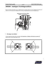
a) Set changeover plate 50 to “N”.<br />
b) Turn throttling screw 42 to the right as far as possible<br />
(maximum boost).<br />
c) Unhook range spring 34 from flapper lever 35 .<br />
d) Check whether the flappers 37 are concentric with the<br />
nozzles 36 . If not, align booster 40 . The fastening<br />
screws of the booster are accessible at the rear side of<br />
the positioner.<br />
e) Push flapper lever 35 alternately to the left and right<br />
several times to align the ball-guided flappers parallel to<br />
the nozzles.<br />
f) Push flapper lever 35 to the left. By turning the hexagonal<br />
rod 38 7 mm A/F set the distance between the<br />
right-hand nozzle and the right-hand flapper to approx.<br />
0.6 mm with the aid of a feeler. Then fasten the hexagonal<br />
rod tight.<br />
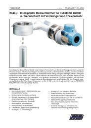
g) Connect the positioner as shown in the test circuit, fig.<br />
28, preset supply air to 1.4 bar.<br />
h) Press flapper lever 35 to the left. If the output y does<br />
not rise to supply air pressure, there are leaks or the<br />
flapper is not correctly positioned (repeat ‘e’).<br />
i) Hook range spring 34 into flapper lever and preset DC<br />
signal w = 10 mA. Proceed as follows to make zero<br />
setting independent of the stroke setting:<br />
k) Press stroke factor lever 31 against stop screw 30 .<br />
I) Set a large stroke factor (approx. 2 mm in front of top<br />
stop) with stroke factor screw 33 .<br />
m) Set zero screw 32 so that the output pressure y =<br />
approx. 0.6 bar and note this value.<br />
n) Set a small stroke factor (approx. 2 mm in front of<br />
bottom stop) with the stroke factor screw 33 .<br />
The output pressure y may not change by more than<br />
±150 mbar in relation to setting m).<br />
o) The stop screw 30 should be adjusted in case of<br />
greater deviations. Repeat settings l) to n) after every<br />
adjustment of the stop screw 30 until the deviation is<br />
less than ±150 mbar.<br />
p) Secure stop screw 30 with varnish.<br />
Put changeover plate 50 back in its original position. Reinstall<br />
positioner or reattach the feedback lever to positioner<br />
shaft.<br />
See page 12 for start-up.<br />
y<br />
SRI 983<br />
Zuluft<br />
Supply air<br />
Fig. 28: Test circuit for single acting positioner<br />
+<br />
+<br />
w<br />
_<br />
_<br />
DC 10 mA