SRI983 Electro-Pneumatic Positioner - explosion ... - Foxboro Eckardt
SRI983 Electro-Pneumatic Positioner - explosion ... - Foxboro Eckardt
SRI983 Electro-Pneumatic Positioner - explosion ... - Foxboro Eckardt

Create successful ePaper yourself
Turn your PDF publications into a flip-book with our unique Google optimized e-Paper software.
4 <strong>SRI983</strong> MI EVE0103 A-(en)<br />
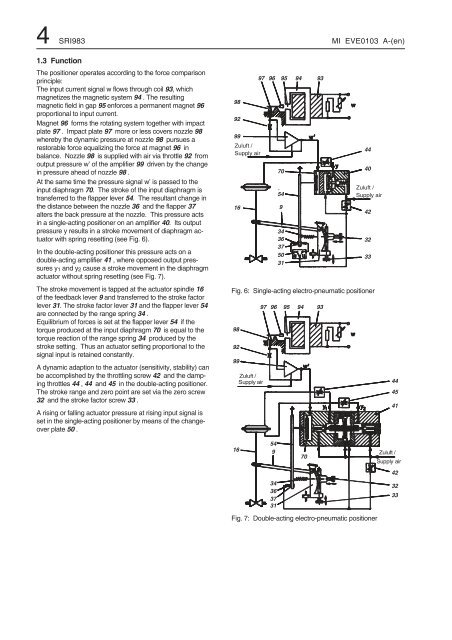
1.3 Function<br />
The positioner operates according to the force comparison<br />
principle:<br />
The input current signal w flows through coil 93, which<br />
magnetizes the magnetic system 94 . The resulting<br />
magnetic field in gap 95 enforces a permanent magnet 96<br />
proportional to input current.<br />
Magnet 96 forms the rotating system together with impact<br />
plate 97 . Impact plate 97 more or less covers nozzle 98<br />
whereby the dynamic pressure at nozzle 98 pursues a<br />
restorable force equalizing the force at magnet 96 in<br />
balance. Nozzle 98 is supplied with air via throttle 92 from<br />
output pressure w’ of the amplifier 99 driven by the change<br />
in pressure ahead of nozzle 98 .<br />
At the same time the pressure signal w’ is passed to the<br />
input diaphragm 70. The stroke of the input diaphragm is<br />
transferred to the flapper lever 54. The resultant change in<br />
the distance between the nozzle 36 and the flapper 37<br />
alters the back pressure at the nozzle. This pressure acts<br />
in a single-acting positioner on an amplifier 40. Its output<br />
pressure y results in a stroke movement of diaphragm actuator<br />
with spring resetting (see Fig. 6).<br />
In the double-acting positioner this pressure acts on a<br />
double-acting amplifier 41 , where opposed output pressures<br />
y1 and y2 cause a stroke movement in the diaphragm<br />
actuator without spring resetting (see Fig. 7).<br />
The stroke movement is tapped at the actuator spindle 16<br />
of the feedback lever 9 and transferred to the stroke factor<br />
lever 31. The stroke factor lever 31 and the flapper lever 54<br />
are connected by the range spring 34 .<br />
Equilibrium of forces is set at the flapper lever 54 if the<br />
torque produced at the input diaphragm 70 is equal to the<br />
torque reaction of the range spring 34 produced by the<br />
stroke setting. Thus an actuator setting proportional to the<br />
signal input is retained constantly.<br />
A dynamic adaption to the actuator (sensitivity, stability) can<br />
be accomplished by the throttling screw 42 and the damping<br />
throttles 44 , 44 and 45 in the double-acting positioner.<br />
The stroke range and zero point are set via the zero screw<br />
32 and the stroke factor screw 33 .<br />
A rising or falling actuator pressure at rising input signal is<br />
set in the single-acting positioner by means of the changeover<br />
plate 50 .<br />
98<br />
92<br />
99<br />
Zuluft /<br />
Supply air<br />
16<br />
70<br />
54<br />
9<br />
34<br />
36<br />
37<br />
50<br />
31<br />
Zuluft /<br />
Supply air<br />
Fig. 6: Single-acting electro-pneumatic positioner<br />
98<br />
92<br />
99<br />
16<br />
Zuluft /<br />
Supply air<br />
97 96 95 94 93<br />
97 96 95 94 93<br />
54<br />
9<br />
34<br />
36<br />
37<br />
31<br />
70<br />
Fig. 7: Double-acting electro-pneumatic positioner<br />
44<br />
40<br />
42<br />
32<br />
33<br />
44<br />
45<br />
41<br />
Zuluft /<br />
Supply air<br />
42<br />
32<br />
33