SRI983 Electro-Pneumatic Positioner - explosion ... - Foxboro Eckardt
SRI983 Electro-Pneumatic Positioner - explosion ... - Foxboro Eckardt
SRI983 Electro-Pneumatic Positioner - explosion ... - Foxboro Eckardt

Create successful ePaper yourself
Turn your PDF publications into a flip-book with our unique Google optimized e-Paper software.
20 <strong>SRI983</strong> MI EVE0103 A-(en)<br />
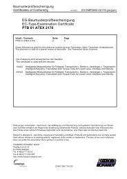
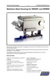
7.2 Replacing the amplifier diaphragm<br />
in the single acting positioner<br />
a) Remove the amplifier 40 (see 7.1)<br />
b) Dismantle the amplifier.<br />
Remove the screw 54 .<br />
Remove the two screws 56.<br />
Remove the strip 55 and flapper lever 35 .<br />
54<br />
35<br />
Fig. 33: Amplifier<br />
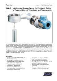
When the four screws 63 are removed, the amplifier can be<br />
dismantled into the following components:<br />
64 housing block A<br />
65 pipe<br />
66 spring<br />
67 diaphragm disk subassembly<br />
68 amplifier diaphragm<br />
69 housing block B<br />
70 input diaphragm subassembly<br />
71 cover<br />
63<br />
56<br />
40<br />
55<br />
71<br />
70<br />
c) Reassemble the amplifier:<br />
Reassemble the components and subassemblies in the<br />
correct position in the sequence specified. Replace<br />
faulty parts.<br />
Put housing block A 64 with the open side facing upwards.<br />
Insert pipe 65 in the hole in the housing block A.<br />
Place spring 66 in position in the diaphragm disk subassembly<br />
67. Insert diaphragm disk subassembly 67 in<br />
housing block 64 so that the pipe 65 passes through<br />
the holes in the diaphragm disk subassembly 67.<br />
Place amplifier diaphragm 68 on the diaphragm disk<br />
subassembly 67 (with the projection facing downwards),<br />
pipe 65 should be inserted in the hole of the<br />
amplifier diaphragm 68.<br />
Place housing block B 69 in its correct position, so that<br />
the pipe 65 is inserted in the relevant hole in housing<br />
block B 69. Press housing block B 69 against housing<br />
block A 64.<br />
Note:<br />
When these two components are pressed together<br />
housing block B 69 should be plane-parallel with<br />
housing block A 64.<br />
If not, why are they misaligned? Is pipe 65 in its correct<br />
position in the holes of housing block A 64 and<br />
housing block B 69 ?)<br />
Insert input diaphragm subassembly 70 in housing<br />
block B 69. Install cover 71 in the right way round<br />
(threaded holes on the amplifier setting side), and screw<br />
the amplifier together. Tighten the four screws 63<br />
uniformly.<br />
d) Screw on the flapper lever 35 again.<br />
e) Install the amplifier (see 7.1)<br />
f) Perform a basic adjustment (see 5.1)<br />
B<br />
69<br />
68<br />
67<br />
66<br />
Fig. 34: Amplifier dismantled<br />
65<br />
A<br />
64