
You also want an ePaper? Increase the reach of your titles
YUMPU automatically turns print PDFs into web optimized ePapers that Google loves.
Quick-Change Installation and Operation Manual<br />
Document #9610-20-1058-27<br />
2.4 Determining The <strong>Tool</strong> <strong>Stand</strong> Configuration<br />
A <strong>TSL</strong> system provides for various Post Module heights and Horizontal Extensions to accommodate a<br />
variety of customer tooling sizes. <strong>Tool</strong> presence detection, vertical and horizontal actuated Debris Shields,<br />
TSI Switches, and Post-mounted <strong>Tool</strong> Support options to provide the most flexible system for <strong>Tool</strong> Changer<br />
models QC-150 and larger. Horizontal or vertical tooling interface plates can be used to secure the <strong>Tool</strong><br />
Changer and customer tooling to the stand. Refer to Section 9.1—<strong>TSL</strong> Systems with Pin and Bushing<br />
Style Mounting Modules or Section 9.5—<strong>TSL</strong> Systems with Hook and Hanger Style Mounting Modules<br />
for example configurations. Refer to Section 2.1—<strong>TSL</strong> System with Pin and Bushing Style Mounting or<br />
Section 2.2—<strong>TSL</strong> System with Hook and Hanger Style Mounting for <strong>TSL</strong> system components available.<br />
To determine the components needed for a <strong>Tool</strong> <strong>Stand</strong>, will require knowledge of the system being<br />
designed. When selecting the <strong>Tool</strong> <strong>Stand</strong> components you will need to consider the following information:<br />
• What model <strong>Tool</strong> Changer will be used and if add on modules will be required for the customer tooling.<br />
• If the <strong>Tool</strong> <strong>Stand</strong> will support one or two tools and what height <strong>Tool</strong> <strong>Stand</strong> will be needed to<br />
accommodate the dimensions and weight of the tooling. Contact ATI for <strong>Tool</strong> <strong>Stand</strong> weight limitations.<br />
• What size, shape, and Center of Gravity of end-effector and tooling<br />
• What mounting style <strong>Tool</strong> <strong>Stand</strong> will be used, pin and bushing or hook and hanger.<br />
• Will customer tooling mount directly to a Vertical <strong>Tool</strong>ing Plate with an interface plate attaching the<br />
<strong>Tool</strong> changer or will the customer tooling and <strong>Tool</strong> Changer attach directly to a <strong>Tool</strong>ing Interface plate.<br />
• Size, reach and capabilities of the robot being used.<br />
• Area available to accommodate the <strong>Tool</strong> <strong>Stand</strong>.<br />
• What options will be required: Horizontal Extension, <strong>Tool</strong> Presence Sensing, <strong>Tool</strong> <strong>Stand</strong> Interlock<br />
Switch, Post-mounted <strong>Tool</strong> Support, and Debris Shields.<br />
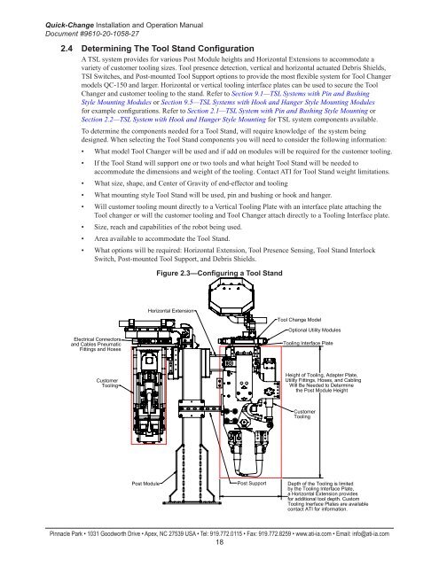
Figure 2.3—Configuring a <strong>Tool</strong> <strong>Stand</strong><br />
Horizontal Extension<br />
<strong>Tool</strong> Change Model<br />
Electrical Connectors<br />
and Cables Pneumatic<br />
Fittings and Hoses<br />
Optional Utility Modules<br />
<strong>Tool</strong>ing Interface Plate<br />
Customer<br />
<strong>Tool</strong>ing<br />
Height of <strong>Tool</strong>ing, Adapter Plate,<br />
Utility Fittings, Hoses, and Cabling<br />
Will Be Needed to Determine<br />
the Post Module Height<br />
Customer<br />
<strong>Tool</strong>ing<br />
Post Module<br />
Post Support<br />
Depth of the <strong>Tool</strong>ing is limited<br />
by the <strong>Tool</strong>ing Interface Plate,<br />
a Horizontal Extension provides<br />
for additional tool depth. Custom<br />
<strong>Tool</strong>ing Inerface Plates are available<br />
contact ATI for information.<br />
Pinnacle Park • 1031 Goodworth Drive • Apex, NC 27539 USA • Tel: 919.772.0115 • Fax: 919.772.8259 • www.ati-ia.com • Email: info@ati-ia.com<br />
18