
You also want an ePaper? Increase the reach of your titles
YUMPU automatically turns print PDFs into web optimized ePapers that Google loves.
Quick-Change Installation and Operation Manual<br />
Document #9610-20-1058-27<br />
(4) M5 Socket<br />
Head Cap Screws<br />
3.4.3 Hook Module with Vertical <strong>Tool</strong>ing Hook Plate or <strong>Tool</strong> Hook Modules<br />
1. Install the Switch Mounting Plate to the <strong>Tool</strong>ing Interface Plate as shown in Figure 3.8.<br />
2. Apply Loctite 242 ® to the three M5 socket flat head cap screws supplied.<br />
3. Secure the Mounting Plate using the three M5 socket flat head cap screws supplied. Tighten to 50 in-lbs.<br />
4. Install the Safety Switch to the Mounting Plate.<br />
5. Apply Loctite 242 ® to the four M5 socket head cap screws supplied with the Safety Switch.<br />
6. Install the Safety Switch to the Mounting Plate using the four M5 socket head cap screws. Tighten to<br />
50 in-lbs. Note: The safety switch actuator arm can be reposition to the desired location refer to the<br />
manufacture instruction for repositioning the actuator.<br />
7. Install the Adapter Plate or the Adjustment Bar to the Hook Module. Note: Place Flat Washer between<br />
the Hook Module and the Adjustment Bar. Secure using the M8 socket head cap screws supplied.<br />
Tighten to 100 in-lbs.<br />
8. If the Trip Dog mounting fasteners do not have pre-applied adhesive, apply Loctite 242 ® to the two M8<br />
socket head cap screws supplied<br />
M5 Socket Flat<br />
Head Cap Screws<br />
Trip Dog<br />
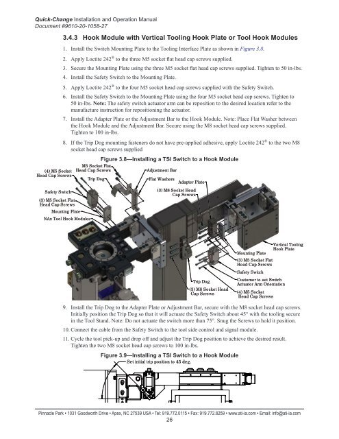
Figure 3.8—Installing a TSI Switch to a Hook Module<br />
Adjustment Bar<br />
Flat Washers<br />
Adapter Plate<br />
Safety Switch<br />
(3) M5 Socket Flat<br />
Head Cap Screws<br />
Mounting Plate<br />
(3) M8 Socket Head<br />
Cap Screws<br />
NAx <strong>Tool</strong> Hook Modules<br />
Mounting Plate<br />
(3) M5 Socket Flat<br />
Head Cap Screws<br />
Safety Switch<br />
Vertical <strong>Tool</strong>ing<br />
Hook Plate<br />
Trip Dog<br />
(3) M8 Socket Head<br />
Cap Screws<br />
Customer to set Switch<br />
Actuator Arm Orientation<br />
(4) M5 Socket<br />
Head Cap Screws<br />
9. Install the Trip Dog to the Adapter Plate or Adjustment Bar, secure with the M8 socket head cap screws.<br />
Initially position the Trip Dog so that it will actuate the Safety Switch about 45° with the tooling secure<br />
in the <strong>Tool</strong> <strong>Stand</strong>. Note: Do not actuate the switch more than 75°. Snug the Screws to hold it position.<br />
10. Connect the cable from the Safety Switch to the tool side control and signal module.<br />
11. Cycle the tool pick-up and drop off and adjust the Trip Dog position to achieve the desired result.<br />
Tighten the two M8 socket head cap screws to 100 in-lbs.<br />
Figure 3.9—Installing a TSI Switch to a Hook Module<br />
Set initial trip position to 45 deg.<br />
Pinnacle Park • 1031 Goodworth Drive • Apex, NC 27539 USA • Tel: 919.772.0115 • Fax: 919.772.8259 • www.ati-ia.com • Email: info@ati-ia.com<br />
26