
You also want an ePaper? Increase the reach of your titles
YUMPU automatically turns print PDFs into web optimized ePapers that Google loves.
Quick-Change Installation and Operation Manual<br />
Document #9610-20-1058-27<br />
4. Operation<br />
The <strong>TSL</strong> system is intended for use with No-touch locking <strong>Tool</strong> Changers only, such as ATI changers QC-150 and<br />
larger.<br />
4.1 <strong>Tool</strong> Change Programming Procedure Tips<br />
• Jog robot so that <strong>TSL</strong> <strong>Tool</strong>ing Interface Plate is directly above the Mounting Module on the Post<br />
Module.<br />
• Carefully lower the <strong>TSL</strong> <strong>Tool</strong>ing Interface Plate toward the Mounting Module so that the post locating<br />
pins are centered in the Plate Bushings.<br />
• When the pins and bushings are nearly touching, adjust the robot position making sure that the <strong>Tool</strong><br />
with Interface Plate are nearly parallel to the Post Module. Be careful not to bind the locating pins<br />
during this procedure.<br />
• Carefully jog the robot down vertically, until all 3 pins and bushings are fully engaged and distance<br />
between the Mounting Module and the <strong>Tool</strong>ing Interface Plate is less than the maximum tool drop off of<br />
3mm (0.118").<br />
• Record this position as drop off point. Note: This can be used as an initial pick up point as well, but<br />
may have to be adjusted depending on the deflection caused by the weight of the tooling.<br />
• If equipped, make sure TSI switch is tripped and Proximity sensor indicates tool is in stand.<br />
• If dropping off the <strong>Tool</strong>, adjust the robot payload to remove the weight of the tooling.<br />
• Move the robot up vertically making sure the <strong>Tool</strong> with Interface Plate are nearly parallel to the Post<br />
Module until the tool is completely clear of the <strong>TSL</strong> Debris Shield envelope, and record this position as<br />
Clear of <strong>Tool</strong> <strong>Stand</strong>.<br />
4.2 <strong>TSL</strong> System with Pin and Bushing Style Mounting Operation<br />
CAUTION: Damage will occur if contact is made between the <strong>TSL</strong> Pin and Bushing<br />
<strong>Tool</strong>ing Plate and the mounting module prior to tool drop-off<br />
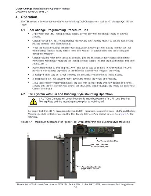
For proper tool drop-off, ATI recommends 3mm (0.118") maximum clearance between <strong>TSL</strong> Pin and Bushing<br />
Mounting Module contact surfaces and the <strong>TSL</strong> <strong>Tool</strong>ing Interface Plate contact surface. See Figure 4.1 for<br />
reference.<br />
Figure 4.1—Maximum Clearance for Proper <strong>Tool</strong> Drop-off for Pin and Bushing Style Mounting<br />
3mm (.118") Gap max.<br />
Prior to <strong>Tool</strong> Drop Off<br />
<strong>Tool</strong>ing Interface Plate<br />
Pin and Bushing Module<br />
(Rigid Module shown)<br />
Pinnacle Park • 1031 Goodworth Drive • Apex, NC 27539 USA • Tel: 919.772.0115 • Fax: 919.772.8259 • www.ati-ia.com • Email: info@ati-ia.com<br />
30