MODAL ANALYSIS - the Dept. of Mechanical Engineering at - Vrije ...
MODAL ANALYSIS - the Dept. of Mechanical Engineering at - Vrije ...
MODAL ANALYSIS - the Dept. of Mechanical Engineering at - Vrije ...

You also want an ePaper? Increase the reach of your titles
YUMPU automatically turns print PDFs into web optimized ePapers that Google loves.
4. Applic<strong>at</strong>ion<br />
In this section, modal analysis will be applied to a sl<strong>at</strong> track, which is safety critical component <strong>of</strong> a<br />
airplane. Sl<strong>at</strong> tracks (see Figure 7) are loc<strong>at</strong>ed <strong>at</strong> <strong>the</strong> leading edge <strong>of</strong> an aircraft wing and make part<br />
<strong>of</strong> a gliding mechanism th<strong>at</strong> is used to enlarge <strong>the</strong> wing surface. The enlargement <strong>of</strong> <strong>the</strong> wing<br />
surface is needed in order to increase <strong>the</strong> lift force <strong>at</strong> reduced velocity during landing and take <strong>of</strong>f.<br />
A sl<strong>at</strong> track <strong>of</strong> an Airbus A320 airplane is considered here. The A320 airplane has 5 sl<strong>at</strong>s per wing.<br />
The first sl<strong>at</strong> (i.e. <strong>the</strong> inboard sl<strong>at</strong> between fuselage and engine) contains 4 sl<strong>at</strong> tracks. The o<strong>the</strong>r 4<br />
sl<strong>at</strong>s have 2 sl<strong>at</strong> tracks each. Safety critical components such as sl<strong>at</strong> tracks are rigorously tested to<br />
prove <strong>the</strong>ir ability to withstand all safety regul<strong>at</strong>ions. It is commonly accepted th<strong>at</strong> <strong>the</strong> track should<br />
outlive <strong>the</strong> plane by five times. Using computer simul<strong>at</strong>ions, it is possible to predict <strong>the</strong> lifetime <strong>of</strong><br />
a track using Finite Element (FE) models. To valid<strong>at</strong>e <strong>the</strong> dynamic behavior <strong>of</strong> <strong>the</strong>se FE models,<br />
experimentally obtained estim<strong>at</strong>es <strong>of</strong> <strong>the</strong> modal parameters are required.<br />
SLAT TRACK<br />
LEADING<br />
EDGE<br />
OF WING<br />
SLAT TRACK<br />
SLAT<br />
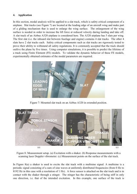
Figure 7: Mounted sl<strong>at</strong> track on an Airbus A320 in extended position.<br />
FORCE SENSOR<br />
STINGER<br />
SHAKER<br />
SHAKER<br />
SCANNING LASER<br />
DOPPLER VIBROMETER<br />
(a) (b) (c)<br />
Figure 8: Measurement setup. (a) Excit<strong>at</strong>ion with a shaker. (b) Response measurements with a<br />
scanning laser Doppler vibrometer. (c) Measurement points on <strong>the</strong> surface <strong>of</strong> <strong>the</strong> sl<strong>at</strong> track.<br />
In Figure 8(a) a shaker is used to excite <strong>the</strong> sl<strong>at</strong> track with a multisine signal. A multisine is a<br />
periodic signal consisting <strong>of</strong> a sum <strong>of</strong> sine waves <strong>at</strong> uniformly distributed frequencies (from 0 Hz to<br />
8192 Hz in this case with a resolution <strong>of</strong> 1 Hz). A force sensor is <strong>at</strong>tached on <strong>the</strong> sl<strong>at</strong> track and is in<br />
contact with <strong>the</strong> shaker through a stinger. The stinger has <strong>the</strong> characteristic <strong>of</strong> being stiff in only<br />
one direction, i.e. th<strong>at</strong> <strong>of</strong> <strong>the</strong> intended excit<strong>at</strong>ion. In this example, one surface <strong>of</strong> <strong>the</strong> track is