

NTN - Precision Rolling Bearings

Create successful ePaper yourself
Turn your PDF publications into a flip-book with our unique Google optimized e-Paper software.
Technical Data<br />
3 Adjustable preload bearing unit<br />
A recent trend in the machine tool industry is a steady<br />
increase of operating speeds. The maximum dmn value<br />
(pitch circle diameter across rolling elements dmmm<br />
multiplied by speed nmin -1 ) reached by main<br />
spindles with air-oil lubricated lubrication can be as high<br />
as 2.5 to 3.8 10 6 . At the same time, main spindles are<br />
requiring increased rigidity. Therefore, main spindle<br />
bearings must be capable of both high-speed operation<br />
and high rigidity. This can be achieved through optimal<br />
preloading.<br />
A fixed preload (spring preload) system is usually<br />
employed to satisfy both these high speed and high<br />
rigidity requirements. A spindle unit with fixed-position<br />
preload that is adjustable for different speed conditions<br />
is advantageous for optimizing the rigidity of the unit.<br />
The <strong>NTN</strong> Adjustable Preload Bearing Unit is a highspeed,<br />
high-rigidity unit that features fixed position<br />
preload that can be adjusted for different speed<br />
conditions.<br />
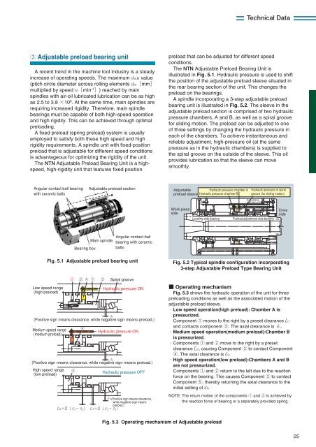
The <strong>NTN</strong> Adjustable Preload Bearing Unit is<br />
illustrated in Fig. 5.1. Hydraulic pressure is used to shift<br />
the position of the adjustable preload sleeve situated in<br />
the rear bearing section of the unit. This changes the<br />
preload on the bearings.<br />
A spindle incorporating a 3-step adjustable preload<br />
bearing unit is illustrated in Fig. 5.2. The sleeve in the<br />
adjustable preload section is comprised of two hydraulic<br />
pressure chambers, A and B, as well as a spiral groove<br />
for sliding motion. The preload can be adjusted to one<br />
of three settings by changing the hydraulic pressure in<br />
each of the chambers. To achieve instantaneous and<br />
reliable adjustment, high-pressure oil (at the same<br />
pressure as in the hydraulic chambers) is supplied to<br />
the spiral groove on the outside of the sleeve. This oil<br />
provides lubrication so that the sleeve can move<br />
smoothly.<br />
Angular contact ball bearing<br />
with ceramic balls<br />
Adjustable preload section<br />
Adjustable<br />
Hydraulic pressure chamber A<br />
preload sleeve Hydraulic pressure chamber B<br />
Hydraulic pressure in spiral<br />
groove (for sliding motion)<br />
Adjustable<br />
preload unit<br />
Work piece<br />
side<br />
Locating side bearing<br />
Preload adjustment side bearing<br />
Drive<br />
side<br />
Bearing box<br />
Main spindle<br />
Angular contact ball<br />
bearing with ceramic<br />
balls<br />
Fig. 5.1 Adjustable preload bearing unit<br />
Low speed range<br />
(high preload)<br />
Medium speed range<br />
(medium preload)<br />
High speed range<br />
(low preload)<br />
<br />
5<br />
2<br />
4<br />
<br />
1 3<br />
Spiral groove<br />
Hydraulic pressure ON<br />
(Positive sign means clearance, while negative sign means preload.)<br />
Hydraulic pressure ON<br />
(Positive sign means clearance, while negative sign means preload.)<br />
Hydraulic pressure OFF<br />
(Positive sign means clearance,<br />
while negative sign means<br />
preload.)<br />
L2 L1 <br />
<br />
<br />
Fig. 5.2 Typical spindle configuration incorporating<br />
3-step Adjustable Preload Type Bearing Unit<br />
Operating mechanism<br />
Fig. 5.3 shows the hydraulic operation of the unit for three<br />
preloading conditions as well as the associated motion of the<br />
adjustable preload sleeve.<br />
Low speed operation(high preload): Chamber A is<br />
pressurized.<br />
Component 1 moves to the right by a preset clearance L1<br />
and contacts component 3. The axial clearance is 1.<br />
Medium speed operation(medium preload):Chamber B<br />
is pressurized.<br />
Components 1 and 2 move to the right by a preset<br />
clearance L2, causing Component 2 to contact Component<br />
4. The axial clearance is2.<br />
High speed operation(low preload):Chambers A and B<br />
are not pressurized.<br />
Components 1 and 2 return to the left due to the reaction<br />
force on the bearing. This causes Component 2 to contact<br />
Component 5, thereby returning the axial clearance to the<br />
initial setting of3.<br />
NOTE: The return motion of the components 1 and 2 is achieved by<br />
the reaction force of bearing or a separately provided spring.<br />
Fig. 5.3 Operating mechanism of Adjustable preload<br />
25


