

NTN - Precision Rolling Bearings

Create successful ePaper yourself
Turn your PDF publications into a flip-book with our unique Google optimized e-Paper software.
Technical Data<br />
(2) Setup of mounted internal clearance gage<br />
¡Place the cylinder gage, onto the bore surface of<br />
clearance adjustment gage as shown in Photo 6.5,<br />
and adjust it with the open/close bolt so that its dial 1<br />
is set to zero (see Photo 6.6).<br />
¡When the reading of dial 1 of the cylinder gage is<br />
zero, adjust the gage bolt so that the pointer of dial 2<br />
points at the red mark (correction amount of the<br />
gage). (Photo 6.6)<br />
With the gage bolt, adjust the gage so that the short<br />
pointer is situated at the scale 2 position. (With the<br />
large size, insert the pin into the hole of the open/<br />
close bolt and make fine-adjustment.)<br />
NOTE 1) Photo 6.6 shows the inner ring and rollers. When<br />
the correction amount of the gage is adjusted, adjust<br />
it only with the thickness gage.<br />
NOTE 2) The pointer of dial 2 is directed to the red mark. The<br />
purpose of this is to compensate clearance error<br />
caused due to the structure of mounted internal<br />
clearance gage. The correction amount can vary<br />
from gage to gage.<br />
NOTE 3) When the pointer of dial 2 is in line with the red<br />
mark, the zero reading on dial 2 coincides with the<br />
zero bearing clearance.<br />
(3) Setting up the mounted internal clearance gage<br />
on the main spindle<br />
¡Mount the inner ring onto the main spindle, and lightly<br />
tighten the bearing nut.<br />
¡Tightening the open/close bolt (see Fig. 6.23) on the<br />
clearance adjustment gage will cause the gage bore<br />
to expand.<br />
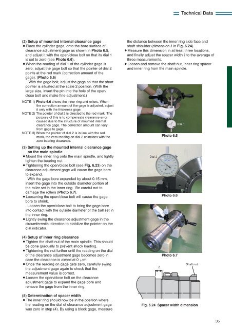
With the gage bore expanded by about 0.15 mm,<br />
insert the gage into the outside diameter portion of<br />
the roller set in the inner ring. Be careful not to<br />
damage the rollers (Photo 6.7).<br />
¡Loosening the open/close bolt will cause the gage<br />
bore to shrink.<br />
Loosen the open/close bolt to bring the gage bore<br />
into contact with the outside diameter of the ball set in<br />
the inner ring.<br />
¡Lightly swing the clearance adjustment gage in the<br />
circumferential direction to stabilize the pointer on the<br />
dial indicator.<br />
the distance between the inner ring side face and<br />
shaft shoulder (dimensionRin Fig. 6.24).<br />
¡Measure this dimension in at least three locations,<br />
and finally adjust the spacer widthRto the average of<br />
three measurements.<br />
¡Loosen and remove the shaft nut, inner ring spacer<br />
and inner ring from the main spindle.<br />
Dial 2<br />
Photo 6.5<br />
Photo 6.6<br />
Dial 1<br />
(4) Setup of inner ring clearance<br />
¡Tighten the shaft nut of the main spindle. This should<br />
be done gradually to prevent shock loading.<br />
¡Tightening the nut further until the reading on the dial<br />
of the clearance adjustment gage becomes zero in<br />
case the clearance is aimed at 0 m.<br />
¡Once the reading on gage gets zero, carefully swing<br />
the adjustment gage again to check that the<br />
measurement value is correct.<br />
¡Loosen the open/close bolt on the clearance<br />
adjustment gage to expand the gage bore and<br />
remove the gage from the inner ring.<br />
R<br />
Photo 6.7<br />
Shaft nut<br />
(5) Determination of spacer width<br />
¡The inner ring should now be in the position where<br />
the reading on the dial of clearance adjustment gage<br />
was zero in step (4). By using a block gage, measure<br />
Fig. 6.24 Spacer width dimension<br />
35


