

NTN - Precision Rolling Bearings

You also want an ePaper? Increase the reach of your titles
YUMPU automatically turns print PDFs into web optimized ePapers that Google loves.
Technical Data<br />
(6) Assembly and check of the mounted roller<br />
outside diameter<br />
¡Insert a spacer of widthR. Then insert the inner ring<br />
and mounting spacer and tighten the shaft nut.<br />
¡According to a procedure similar to that in steps (3)<br />
Setting up the mounted internal clearance gage on<br />
the main spindle and (4) Setup of inner ring<br />
clearance, check the mounted roller outside diameter<br />
and the clearance setting. Note this process is only a<br />
re-check procedure, and may be omitted once the<br />
clearance measurements fall in a smaller range.<br />
Clearance correction factor and mounted<br />
internal clearance reading<br />
(1) Clearance correction factor<br />
Because of the structure of the <strong>NTN</strong> mounted internal<br />
clearance adjustment gage, the ratio of the clearance<br />
reading on location for measurement to the reading on<br />
dial indicator is 1:2.5 (clearance indication factor). The<br />
clearance reading on the dial indicator is 2.5 times as<br />
large as the remaining internal clearance. For<br />
reference, a clearance reading conversion table is<br />
given in Table 6.4.<br />
NOTE: Note that the clearance correction factor of certain<br />
bearing numbers is not 1:2.5. Correction factor is<br />
given on the table of inspection results.<br />
(2) Remaining internal clearance (where clearance<br />
indication value 1:2.5)<br />
The reading on the dial indicator is converted into a<br />
mounted internal clearance in the<br />
following manner:<br />
¡CASE 1: The reading relative to the<br />
zero point is in the clockwise<br />
direction (CW) (Fig. 6.25). The<br />
value of the mounted internal<br />
clearance (+) is 1/2.5 times as large<br />
as the reading on dial gage.<br />
Reading on dial gage in Fig. 6.25 = 2.5<br />
Remaining internal clearance = 2.5/2.5 = (+)1m<br />
¡CASE 2: The reading relative to the zero point is in<br />
the counterclockwise direction (CCW) (Fig. 6.26).<br />
The value of the mounted internal clearance (-) is<br />
Table 6.4 Clearance reading conversion table<br />
<br />
<br />
<br />
Fig.6.25<br />
1/2.5 times as large as the reading<br />
on dial gage.<br />
Reading on dial gage in Fig. 6.26<br />
= 5.0<br />
Remaining internal clearance =<br />
5.0/2.5 = (-)2m<br />
Setup of mounted internal clearance<br />
When setting the mounted internal clearance to a<br />
specific negative or positive value, the zero point on dial<br />
indicator by a value [targeted clearance multiplied by<br />
2.5] may be shifted prior to the setup of the clearance<br />
adjustment gage. (In case that the mounted clearance<br />
value is divided by the correction factor, it is not<br />
necessary to the value [targeted clearance multiplied by<br />
2.5])<br />
(2.5: clearance correction factor)<br />
<br />
<br />
Fig. 6.27 Adjustment for<br />
negative clearance<br />
(remaining internal<br />
clearance: -0.8 m)<br />
<br />
<br />
Fig. 6.28 Adjustment for<br />
positive clearance<br />
(remaining internal<br />
clearance: +1.0 m)<br />
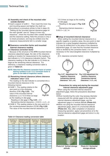
Precautions for using and storing the mounted<br />
internal clearance adjustment gage<br />
When using the mounted internal clearance<br />
adjustment gage, follow the precautions described<br />
below:<br />
¡When transferring the outer ring raceway diameter<br />
measured with the cylinder gage to the mounted<br />
internal clearance adjustment gage, use the<br />
adjustment gage in a vertical attitude (Photo 6.8).<br />
¡When not using the mounted internal clearance<br />
adjustment gage, place it in a horizontal attitude<br />
(Photo 6.9). Also, after completion of clearance<br />
measuring operation, apply rust-preventive oil to the<br />
internal clearance adjustment gage and store in a dry<br />
location.<br />
<br />
<br />
<br />
Fig.6.26<br />
Reading on<br />
dial gage<br />
(m)<br />
0.5<br />
1.0<br />
1.5<br />
2.0<br />
2.5<br />
3.0<br />
3.5<br />
4.0<br />
4.5<br />
5.0<br />
Remaining internal<br />
clearance on location<br />
for measurement<br />
(m)<br />
0.2<br />
0.4<br />
0.6<br />
0.8<br />
1.0<br />
1.2<br />
1.4<br />
1.6<br />
1.8<br />
2.0<br />
Reading on<br />
dial gage<br />
(m)<br />
5.5<br />
6.0<br />
6.5<br />
7.0<br />
7.5<br />
8.0<br />
8.5<br />
9.0<br />
9.5<br />
10.0<br />
Remaining internal<br />
clearance on location<br />
for measurement<br />
(m)<br />
2.2<br />
2.4<br />
2.6<br />
2.8<br />
3.0<br />
3.2<br />
3.4<br />
3.6<br />
3.8<br />
4.0<br />
Photo 6.8 Vertical storage<br />
attitude<br />
Photo 6.9 Horizontal<br />
storage attitude<br />
36


