Installation Guide
HmfH3060Vqg
HmfH3060Vqg

Create successful ePaper yourself
Turn your PDF publications into a flip-book with our unique Google optimized e-Paper software.
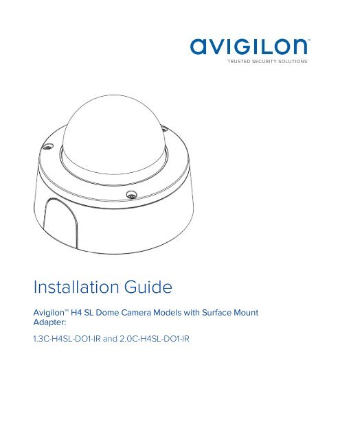
<strong>Installation</strong> <strong>Guide</strong><br />
Avigilon H4 SL Dome Camera Models with Surface Mount<br />
Adapter:<br />
1.3C-H4SL-DO1-IR and 2.0C-H4SL-DO1-IR
Important Safety Information<br />
This manual provides installation and operation information and precautions for the use of this camera. Incorrect<br />
installation could cause an unexpected fault. Before installing this equipment read this manual carefully. Please<br />
provide this manual to the owner of the equipment for future use.<br />
The Warning symbol indicates the presence of dangerous voltage within and outside the product<br />
enclosure that may constitute a risk of electric shock, serious injury or death to persons if proper<br />
precautions are not followed.<br />
The Caution symbol alerts the user to the presence of hazards that may cause minor or moderate injury<br />
to persons, damage to property or damage to the product itself if proper precautions are not followed.<br />
WARNING — Failure to observe the following instructions may result in severe injury or death.<br />
• <strong>Installation</strong> must be performed by qualified personnel only, and must conform to all local codes.<br />
• This product is intended to be supplied by Power over Ethernet (PoE) that is a “Limited Power Source” or<br />
“LPS”, rated 48 VDC, 7W min.<br />
• Any external power supply connected to this product may only be connected to another Avigilon<br />
product of the same model series. External power connections must be properly insulated.<br />
• Do not connect directly to mains power for any reason.<br />
CAUTION — Failure to observe the following instructions may result in injury or damage to the camera.<br />
• Do not expose the camera directly to high levels of x-ray, laser, or UV radiation. Direct exposure may<br />
cause permanent damage to the image sensor.<br />
• Do not install near any heat sources such as radiators, heat registers, stoves, or other sources of heat.<br />
• Do not subject the cables to excessive stress, heavy loads or pinching.<br />
• Do not open or disassemble the device. There are no user serviceable parts.<br />
• Refer all servicing to qualified personnel. Servicing may be required when the device has been damaged<br />
(such as from a liquid spill or fallen objects), has been exposed to rain or moisture, does not operate<br />
normally, or has been dropped.<br />
• Do not use strong or abrasive detergents when cleaning the device body.<br />
• Use only accessories recommended by Avigilon.<br />
Regulatory Notices<br />
This device complies with part 15 of the FCC Rules. Operation is subject to the following two conditions: (1) this<br />
device may not cause harmful interference, and (2) this device must accept any interference received, including<br />
interference that may cause undesired operation.<br />
ii
This Class B digital apparatus complies with Canadian ICES-003.<br />
FCC Notice<br />
This equipment has been tested and found to comply with the limits for a Class B digital device, pursuant to Part<br />
15 of the FCC rules. These limits are designed to provide reasonable protection against harmful interference in a<br />
residential installation. This equipment generates, uses and can radiate radio frequency energy and, if not<br />
installed and used in accordance with the instructions, may cause harmful interference to radio communications.<br />
However, there is no guarantee that interference will not occur in a particular installation. If this equipment does<br />
cause harmful interference to radio or television reception, which can be determined by turning the equipment<br />
off and on, the user is encouraged to try to correct the interference by one or more of the following measures:<br />
• Reorient or relocate the receiving antenna.<br />
• Increase the separation between the equipment and the receiver.<br />
• Connect the equipment into an outlet on a circuit different from that to which the receiver is connected.<br />
• Consult the dealer or an experienced radio/TV technician for help.<br />
Changes or modifications made to this equipment not expressly approved by Avigilon Corporation or parties<br />
authorized by Avigilon Corporation could void the user’s authority to operate this equipment.<br />
Disposal and Recycling Information<br />
When this product has reached the end of its useful life, please dispose of it according to your local<br />
environmental laws and guidelines.<br />
Risk of fire, explosion, and burns. Do not disassemble, crush, heat above 100 °C (212 °F), or incinerate.<br />
European Union:<br />
This symbol means that according to local laws and regulations your product should be disposed of separately<br />
from household waste. When this product reaches its end of life, take it to a collection point designated by local<br />
authorities. Some collection points accept products for free. The separate collection and recycling of your<br />
product at the time of disposal will help conserve natural resources and ensure that it is recycled in a manner<br />
that protects human health and the environment.<br />
Legal Notices<br />
© 2016, Avigilon Corporation. All rights reserved. AVIGILON, the AVIGILON logo, AVIGILON CONTROL<br />
CENTER, ACC, and TRUSTED SECURITY SOLUTIONS are trademarks of Avigilon Corporation. Other product<br />
names mentioned herein may be the trademarks of their respective owners. The absence of the symbols and<br />
® in proximity to each trademark in this document is not a disclaimer of ownership of the related trademark.<br />
Avigilon Corporation protects its innovations with patents issued in the United States of America and other<br />
iii
jurisdictions worldwide: http://www.avigilon.com/patents. Unless stated explicitly and in writing, no license is<br />
granted with respect to any copyright, industrial design, trademark, patent or other intellectual property rights of<br />
Avigilon Corporation or its licensors.<br />
Disclaimer<br />
This document has been compiled and published covering the latest product descriptions and specifications.<br />
The contents of this document and the specifications of the products discussed herein are subject to change<br />
without notice. Avigilon Corporation reserves the right to make any such changes without notice. Neither<br />
Avigilon Corporation nor any of its affiliated companies: (1) guarantees the completeness or accuracy of the<br />
information contained in this document; or (2) is responsible for your use of, or reliance on, the information.<br />
Avigilon Corporation shall not be responsible for any losses or damages (including consequential damages)<br />
caused by reliance on the information presented herein.<br />
Avigilon Corporation<br />
http://www.avigilon.com<br />
PDF-H4SLDO-A<br />
Revision: 1 - EN<br />
20160906<br />
iv
Table of Contents<br />
Overview 1<br />
Cover View 1<br />
Mounting Adapter View 2<br />
Camera Base Bottom View 3<br />
Camera Base Front View 4<br />
Camera Base Rear View 5<br />
<strong>Installation</strong> 6<br />
Required Tools and Materials 6<br />
Camera Package Contents 6<br />
<strong>Installation</strong> Steps 6<br />
Removing the Dome Cover 7<br />
Inserting Cables through the Sealing Grommet 7<br />
Using the Surface Mount Adapter 8<br />
Mounting the Dome Camera Using the Bottom Cable Entry 8<br />
Mounting the Dome Camera Using the Side Cable Entry 9<br />
Mounting the Dome Camera to an Electrical Box 12<br />
Installing the Camera Base to the Mounting Adapter 12<br />
(Optional) Using the USB Wi-Fi Adapter 14<br />
Assigning an IP Address 14<br />
Accessing the Live Video Stream 14<br />
Aiming the Dome Camera 14<br />
(Optional) Configuring microSD Card Storage 16<br />
Installing the Dome Cover 17<br />
Zooming and Focusing the Dome Camera 17<br />
Configuring the Camera 17<br />
For More Information 18<br />
LED Indicators 19<br />
Removing the Dome Camera from the Mounting Adapter 20<br />
Resetting to Factory Default Settings 21<br />
Setting the IP Address Using the ARP/Ping Method 22<br />
Specifications 23<br />
Limited Warranty and Technical Support 25<br />
v
Overview<br />
Cover View<br />
1. Dome cover<br />
Vandal resistant dome cover.<br />
2. Surface mount adapter<br />
Used to mount the dome camera to a wall, ceiling or electrical box.<br />
3. Tamper resistant screws<br />
Torx captive screws to fix the dome cover to the base.<br />
4. Side cable entry cover<br />
Covers the side cable entry hole.<br />
Overview 1
Mounting Adapter View<br />
1. Lanyard<br />
Connects to the lanyard anchor on the dome camera base.<br />
2. Camera housing clips<br />
Snaps to hold camera module during installation.<br />
3. Cable entry hole<br />
An entry hole for the cables required for camera operation.<br />
4. Mounting holes<br />
Holes for mounting the adapter to the following:<br />
A — UK standard single gang box<br />
B — Octagon gang box<br />
D — US standard single gang box<br />
Mounting Adapter View 2
Camera Base Bottom View<br />
1. Cable entry hole<br />
An entry hole for the cables required for camera operation.<br />
2. Lanyard anchor<br />
The safety lanyard attaches to the anchor to prevent the camera from falling during installation.<br />
3. Vent<br />
Vent to allow moisture vapor to escape the sealed housing and equalize pressure.<br />
Camera Base Bottom View 3
Camera Base Front View<br />
1. IR illuminator<br />
Provides scene illumination in the IR spectrum.<br />
2. Ethernet port<br />
Accepts power and Ethernet connection to the network.<br />
The camera can only be powered by Power over Ethernet (PoE). Server communication and image data<br />
transmission also occur over this connection.<br />
3. Connection status LED<br />
Provides information about camera operation. For more information, see LED Indicators on page 19.<br />
4. Link LED<br />
Indicates if there is an active connection in the Ethernet port.<br />
5. microSD card slot<br />
Accepts a microSD card for onboard storage.<br />
Camera Base Front View 4
Camera Base Rear View<br />
1. Azimuth control<br />
Provides control of the image angle.<br />
2. Tilt lock thumb screw<br />
Provides a locking mechanism for the image tilt adjustment.<br />
3. Pan lock latch<br />
Provides a locking mechanism for the image pan adjustment<br />
4. Micro USB port<br />
Accepts a micro USB to USB adapter. Only required when using the Avigilon USB Wi-Fi Adapter.<br />
5. Serial number tag<br />
Device information, product serial number and part number label.<br />
Camera Base Rear View 5
<strong>Installation</strong><br />
Required Tools and Materials<br />
The following tools are required to complete the camera installation but are not included in the camera<br />
package:<br />
• No. 2 Phillips screwdriver — for attaching camera to an electrical box or mounting surface.<br />
• T20 Pin-In Torx driver<br />
Camera Package Contents<br />
Ensure the package contains the following:<br />
• Avigilon H4 SL Dome Camera<br />
• Mounting template sticker<br />
• RJ-45 grommet piercing cap<br />
• 4 screws and anchors for solid walls<br />
• Surface mount adapter<br />
• Side conduit cover<br />
• Side conduit plate (2 sizes)<br />
• Conduit grommet<br />
• Cable entry grommet<br />
<strong>Installation</strong> Steps<br />
Complete the following steps to install the camera:<br />
Removing the Dome Cover 7<br />
Inserting Cables through the Sealing Grommet 7<br />
Using the Surface Mount Adapter 8<br />
Installing the Camera Base to the Mounting Adapter 12<br />
(Optional) Using the USB Wi-Fi Adapter 14<br />
Assigning an IP Address 14<br />
Accessing the Live Video Stream 14<br />
Aiming the Dome Camera 14<br />
(Optional) Configuring microSD Card Storage 16<br />
Installing the Dome Cover 17<br />
<strong>Installation</strong> 6
Zooming and Focusing the Dome Camera 17<br />
Configuring the Camera 17<br />
Removing the Dome Cover<br />
NOTE: Be careful not to scratch or touch the dome bubble. The resulting marks or fingerprints may affect the<br />
overall image quality. Keep the protective covers on the outside of the dome bubble until the installation is<br />
complete.<br />
• Remove the dome cover by releasing the elastic strap holding the dome cover to the camera base.<br />
Inserting Cables through the Sealing Grommet<br />
Always use the provided sealing grommet to prevent dust and debris from entering the camera.<br />
Removing the Dome Cover 7
1. Remove the sealing grommet from the camera base.<br />
2. Push the Ethernet cable through the grommet by one of the following methods:<br />
a. If the Ethernet cable is uncrimped, push the cable through the grommet.<br />
b. If the Ethernet cable is already crimped, place the grommet piercing cap on the Ethernet<br />
connector then push the cable through the grommet.<br />
Ensure that the orientation of the cable and grommet matches the one shown in the image.<br />
Using the Surface Mount Adapter<br />
The dome camera is provided with a surface mount adapter that can be mounted to a wall, ceiling or electrical<br />
box.<br />
If the dome camera needs to be installed in a different way, use one of the other mounting adapter options and<br />
refer to their installation manuals for more information.<br />
• In-ceiling mounting adapter (H4SL-MT-DCIL)<br />
• Pendant NPT mounting adapter (H4SL-MT-NPTA)<br />
o<br />
Pendant wall mounting adapter (H4SL-MT-WALL) — must be used with NPT mounting adapter.<br />
Mounting the Dome Camera Using the Bottom Cable Entry<br />
Perform the following steps if the required cables will be coming from inside the mounting surface and the<br />
camera will be mounted immediately over the cable hole. Use this procedure on surfaces that can be easily<br />
drilled into, and when the cables should be kept out of sight.<br />
Perform the following steps to mount the dome camera to a ceiling or wall:<br />
1. Use the mounting template to drill 4 mounting holes into the mounting surface and drill the cable entry<br />
hole.<br />
2. Pull the required Ethernet cable through the cable entry hole.<br />
Make sure the Ethernet cable is threaded through the sealing grommet from the camera base. For more<br />
information, see Inserting Cables through the Sealing Grommet on the previous page<br />
3. Drive 4 screws to fasten the mounting adapter to the ceiling or wall.<br />
Using the Surface Mount Adapter 8
Mounting the Dome Camera Using the Side Cable Entry<br />
Perform the following steps if you will be mounting to a surface with the required cables coming out of an<br />
external conduit pipe. Use this procedure if the mounting surface cannot be easily cut, or when cables must be<br />
brought along the outside of the mounting surface.<br />
1. Use the mounting template to drill four mounting holes into the mounting surface.<br />
Make sure the mounting template is aligned to where the conduit will enter the mounting adapter.<br />
2. Pull the required Ethernet cable through the conduit.<br />
3. Slide the side cable cover off the mounting adapter.<br />
Mounting the Dome Camera Using the Side Cable Entry 9
4. Depending on the conduit used, make the required adjustments to the side cable entry hole:<br />
• If you are using a 1/2" or 20 mm interior conduit, install the provided side conduit cover on to the<br />
mounting adapter.<br />
• If using ¾” or 25 mm interior conduit, remove the center knockout piece on the provided side<br />
conduit cover then install the side conduit cover on to the mounting adapter.<br />
Mounting the Dome Camera Using the Side Cable Entry 10
• If using ½” or ¾” exterior conduit, install a conduit plate to an external conduit adaptor then slide<br />
the mounting adaptor over the conduit and plate assembly. Ensure the plate is compatible with the<br />
type of conduit used.<br />
You may need to cut off part of the rubber gasket on the mounting adapter to make room for the<br />
plate.<br />
Mounting the Dome Camera Using the Side Cable Entry 11
5. Drive 4 screws to fasten the mounting adapter to the ceiling or wall.<br />
Mounting the Dome Camera to an Electrical Box<br />
Perform the following steps if the required electrical components and cables will be contained in an electrical<br />
gang box inside the mounting surface.<br />
1. Pull the required Ethernet cable through the cable entry hole.<br />
Make sure the Ethernet cable is threaded through the sealing grommet from the camera base. For more<br />
information, see Inserting Cables through the Sealing Grommet on page 7<br />
2. Use pan head screws to install the mounting adapter to the electrical box.<br />
Select the hole configuration that matches the electrical box shape:<br />
A — UK standard single gang box<br />
B — Octagon gang box<br />
D — US standard single gang box<br />
Installing the Camera Base to the Mounting Adapter<br />
After you install the mounting adapter, mount the camera base to the adapter.<br />
Mounting the Dome Camera to an Electrical Box 12
1. Attach the lanyard on the mounting adapter to the anchor on the camera base.<br />
2. Pull the required Ethernet cable through the cable entry hole on the camera base.<br />
3. Install the grommet into the cable entry hole on the camera base.<br />
Make sure the grommet flange is securely seated on the inside and outside of the cable entry hole.<br />
4. Connect the cable to the Ethernet port.<br />
The Link LED will turn on once a network link has been established.<br />
5. Align the large orange arrow on the camera base to the side cable entry hole on the mounting adapter<br />
then press the camera base into the mounting adapter. The camera base clicks into place and is held<br />
securely.<br />
Installing the Camera Base to the Mounting Adapter 13
(Optional) Using the USB Wi-Fi Adapter<br />
If you have a USB Wi-Fi Adapter (H4-AC-WIFI), attach it to the camera's micro USB port to access the camera's<br />
mobile web interface.<br />
After you connect to the Wi-Fi signal broadcast by the adapter, you can access the mobile web interface from<br />
any mobile device using the following address:<br />
http://camera.lan<br />
For more information about configuring the camera from the mobile web interface see Avigilon USB Wi-Fi<br />
Adapter System User <strong>Guide</strong>.<br />
NOTE:The camera will reserve the 10.11.22.32/28 subnet forinternal use while the USBWi-Fi Adapteris plugged in.<br />
Assigning an IP Address<br />
The camera automatically obtains an IP address when it is connected to a network.<br />
NOTE: If the camera cannot obtain an IP address from a DHCP server, it will use Zero Configuration Networking<br />
(Zeroconf) to choose an IP address. When set using Zeroconf, the IP address is in the 169.254.0.0/16 subnet.<br />
The IP address settings can be changed using one of the following methods:<br />
• The mobile web interface using the USB Wifi Adapter. For more information, see (Optional) Using the USB<br />
Wi-Fi Adapter above.<br />
• Camera's web browser interface: http:///<br />
• Network Video Management software application (for example, Avigilon Control Center (ACC)).<br />
• ARP/Ping method. For more information, see Setting the IP Address Using the ARP/Ping Method on<br />
page 22.<br />
NOTE: The default camera username is administrator with no password.<br />
Accessing the Live Video Stream<br />
Live video stream can be viewed using one of the following methods:<br />
• The mobile web interface using the USB Wifi Adapter. For more information, see (Optional) Using the USB<br />
Wi-Fi Adapter above.<br />
• Web browser interface: http://< camera IP address>/<br />
• Network Video Management software application (for example, the Avigilon Control Center software).<br />
NOTE: The default camera username is administrator with no password.<br />
Aiming the Dome Camera<br />
Reference the camera's live stream as you aim the camera.<br />
(Optional) Using the USB Wi-Fi Adapter 14
1. Unlock the pan lock latch on the camera base, then pan the lens until it is aimed in the correct direction.<br />
If the camera stops panning before it reaches its final destination, stop and pan the camera in the<br />
opposite direction.<br />
2. Loosen the tilt lock thumb screw to tilt the lens.<br />
3. Lock the pan lock latch and tighten the tilt lock screw to secure the dome camera’s position.<br />
Aiming the Dome Camera 15
4. Rotate the azimuth control ring to set the image to the correct angle.<br />
5. In the camera web browser interface or the Avigilon Control Center software, adjust the camera’s Image<br />
and Display settings.<br />
(Optional) Configuring microSD Card Storage<br />
To use the camera's SD card storage feature, you must insert an microSD card into the card slot.<br />
It is recommended that the microSD card have a write speed of class 10 or better. If the microSD card does not<br />
meet the recommended write speed, the recording performance may suffer and result in the loss of frames or<br />
footage.<br />
1. Insert a microSD card into the camera.<br />
CAUTION — Do not force the microSD card into the camera or you may damage the card and the<br />
camera.<br />
2. Access the camera’s web interface to enable the onboard storage feature. For more information, see the<br />
Avigilon High Definition H.264 Camera Web Interface User <strong>Guide</strong>.<br />
(Optional) Configuring microSD Card Storage 16
Installing the Dome Cover<br />
1. Attach the dome cover to the base by tightening the screws with the Torx driver.<br />
2. Remove the protective cover on the outside of the dome bubble.<br />
Zooming and Focusing the Dome Camera<br />
Ensure this procedure is performed after the dome cover is installed, so you can accommodate for the focus<br />
shift caused by the dome bubble.<br />
NOTE: If the camera is powered while the temperature is below -30 °C (-22 °F), the zoom and focus may be<br />
disabled for the first 45 minutes while the camera warms up.<br />
• In the camera web browser interface or the Avigilon Control Center software, use the camera’s Image<br />
and Display settings to zoom and focus the camera.<br />
a. Use the zoom buttons to zoom the camera in or out.<br />
b. Click Auto Focus to focus the lens.<br />
c. Use the focus near and far buttons to manually adjust the focus.<br />
Configuring the Camera<br />
Once installed, use one of the following methods to configure the camera:<br />
• If you have the USB Wifi Adapter, you can access the mobile web interface to configure the camera. For<br />
more information, see Avigilon USB Wi-Fi Adapter System User <strong>Guide</strong>.<br />
• If you have installed multiple cameras, you can use the Avigilon Camera Configuration Tool to configure<br />
common settings. For more information, see the Avigilon Camera Configuration Tool User <strong>Guide</strong>.<br />
• If the camera is connected to the Avigilon Control Center system, you can use the client software to<br />
configure the camera. For more information, see the Avigilon Control Center Client User <strong>Guide</strong>.<br />
• If the camera is connected to a third-party network management system, you can configure the camera's<br />
specialty features in the camera's web browser interface. For more information, see the Avigilon H.264<br />
Web Interface User <strong>Guide</strong>.<br />
Installing the Dome Cover 17
For More Information<br />
Additional information about setting up and using the device is available in the following guides:<br />
• Avigilon Control Center Client User <strong>Guide</strong><br />
• Avigilon High Definition H.264 Web Interface User <strong>Guide</strong><br />
• Avigilon Camera Configuration Tool User <strong>Guide</strong><br />
The manuals are available on the Avigilon website: http://www.avigilon.com/support-and-downloads<br />
For More Information 18
LED Indicators<br />
Once connected to the network, the Connection Status LED will display the progress in connecting to the<br />
Network Video Management software.<br />
The following table describes what the LEDs indicate:<br />
Connection State<br />
Connection Status<br />
LED<br />
Description<br />
Obtaining IP Address<br />
Discoverable<br />
Upgrading Firmware<br />
Connected<br />
One short flash every<br />
second<br />
Two short flashes<br />
every second<br />
Two short flashes<br />
and one long flash<br />
every second<br />
On<br />
Attempting to obtain an IP address.<br />
Obtained an IP address but is not connected to the<br />
Network Video Management software.<br />
Updating the firmware.<br />
Connected to the Network Video Management software or an<br />
ACC Server.<br />
LED Indicators 19
Removing the Dome Camera from the Mounting<br />
Adapter<br />
1. Loosen the Torx screws and remove the dome cover.<br />
2. Locate the small orange arrows that point at the camera housing clips.<br />
3. Insert the grommet piercing cap against one of the camera housing clips.<br />
4. Lever one side of the camera base out of the clip.<br />
5. Lift the camera base out of the adapter.<br />
Removing the Dome Camera from the Mounting Adapter 20
Resetting to Factory Default Settings<br />
If the camera no longer functions as expected, you can choose to reset the camera to its factory default settings.<br />
Use the firmware revert button to reset the camera. The firmware revert button is shown in the following<br />
diagram:<br />
1. Ensure the camera is powered on.<br />
2. Using a straightened paperclip or similar tool, gently press and hold the firmware revert button.<br />
3. Release the button after three seconds.<br />
CAUTION — Do not apply excessive force. Inserting the tool too far will damage the camera.<br />
Resetting to Factory Default Settings 21
Setting the IP Address Using the ARP/Ping Method<br />
Complete the following steps to configure the camera to use a specific IP address:<br />
NOTE: The ARP/Ping Method will not work if the Disable setting static IP address through ARP/Ping method<br />
check box is selected in the camera's web browser interface. For more information, see the Avigilon High<br />
Definition H.264 Web Interface User <strong>Guide</strong>.<br />
1. Locate and copy down the MAC Address (MAC) listed on the Serial Number Tag for reference.<br />
2. Open a Command Prompt window and enter the following commands:<br />
a. arp -s <br />
For example: arp -s 192.168.1.10 00-18-85-12-45-78<br />
b. ping -l 123 -t <br />
For example: ping -l 123 -t 192.168.1.10<br />
3. Reboot the camera.<br />
4. Close the Command prompt window when you see the following message:<br />
Reply from : ...<br />
Setting the IP Address Using the ARP/Ping Method 22
Specifications<br />
Camera<br />
Lens<br />
USB Port USB 2.0<br />
SD Storage<br />
Network<br />
Network<br />
Cabling Type<br />
Connector<br />
API<br />
Device Management<br />
Protocols<br />
Security<br />
Streaming Protocols<br />
Mechanical<br />
Dimensions<br />
L x W x H<br />
Weight<br />
Dome Bubble<br />
Body<br />
Housing<br />
Finish<br />
Adjustment Range<br />
Electrical<br />
Power Consumption<br />
Power Source<br />
RTC Backup Battery<br />
Environmental<br />
Operating<br />
Temperature<br />
Storage Temperature<br />
Humidity<br />
3-9 mm, motorized, varifocal<br />
microSD/microSDHC/microSDXC slot – minimum class 6; class 10/UHS-1 or better<br />
recommended<br />
100Base-TX<br />
CAT5<br />
RJ-45<br />
ONVIF compliance version 1.02, 2.00, Profile S (www.onvif.org)<br />
SNMP v2c<br />
SNMP v3<br />
Password protection, HTTPS encryption, digest authentication, WS authentication, user<br />
access log, 802.1x port based authentication.<br />
IPv4, HTTP, HTTPS, SOAP, DNS, NTP, RTSP, RTCP, RTP, TCP, UDP, IGMP, ICMP, DHCP,<br />
Zeroconf, ARP, RTP/UDP, RTP/UDP multicast, RTP/RTSP/TCP, RTP/RTSP/HTTP/TCP,<br />
RTP/RTSP/HTTPS/TCP, HTTP<br />
147 mm x 147 mm x 119 mm; (5.8” x 5.8” x 4.7”)<br />
0.78 kg (1.72 lbs)<br />
Polycarbonate, clear<br />
Polycarbonate<br />
Surface mount, vandal resistant<br />
Fog coat, cool grey<br />
360° pan, 30° – 95° tilt, ±180° azimuth<br />
7 W max<br />
PoE: IEEE802.3af Class 3 compliant<br />
3V manganese lithium<br />
-30 °C to +60 °C (-22 °F to 140 °F)<br />
-10 °C to +70 °C (14 °F to 158 °F)<br />
0-95% non-condensing<br />
Specifications 23
Certifications<br />
Certifications<br />
Safety<br />
Environmental<br />
Electromagnetic<br />
Emissions<br />
Electromagnetic<br />
Immunity<br />
UL<br />
cUL<br />
CE<br />
ROHS<br />
WEEE<br />
RCM<br />
EAC<br />
KC<br />
UL 60950-1<br />
CSA 60950-1<br />
IEC/EN 60950-1<br />
IEC 62471<br />
IK10 Impact Rating<br />
Meets IEC 60529 IP66 Weather Rating<br />
IEC/UL/CSA 60950-22<br />
FCC Part 15 Subpart B Class B<br />
EN 55022 Class B<br />
EN 55032<br />
IC ICES-003 Class B<br />
EN 61000-6-3<br />
EN 61000-3-2<br />
EN 61000-3-3<br />
KN 32<br />
EN 55024<br />
EN 61000-6-1<br />
EN 50130-4<br />
KN 35<br />
Specifications 24
Limited Warranty and Technical Support<br />
Avigilon warrants to the original consumer purchaser that this product will be free of defects in material and<br />
workmanship for a period of 3 years from date of purchase.<br />
The manufacturer’s liability hereunder is limited to replacement of the product, repair of the product or<br />
replacement of the product with repaired product at the discretion of the manufacturer. This warranty is void if<br />
the product has been damaged by accident, unreasonable use, neglect, tampering or other causes not arising<br />
from defects in material or workmanship. This warranty extends to the original consumer purchaser of the<br />
product only.<br />
AVIGILON DISCLAIMS ALL OTHER WARRANTIES EXPRESSED OR IMPLIED INCLUDING, WITHOUT LIMITATION,<br />
ANY IMPLIED WARRANTIES OF MERCHANTABILITY OR FITNESS FOR A PARTICULAR PURPOSE, EXCEPT TO<br />
THE EXTENT THAT ANY WARRANTIES IMPLIED BY LAW CANNOT BE VALIDLY WAIVED.<br />
No oral or written information, advice or representation provided by Avigilon, its distributors, dealers, agents or<br />
employees shall create another warranty or modify this warranty. This warranty states Avigilon’s entire liability<br />
and your exclusive remedy against Avigilon for any failure of this product to operate properly.<br />
In no event shall Avigilon be liable for any indirect, incidental, special, consequential, exemplary, or punitive<br />
damages whatsoever (including but not limited to, damages for loss of profits or confidential or other<br />
information, for business interruption, for personal injury, for loss of privacy, for failure to meet any duty including<br />
of good faith or of reasonable care, for negligence, and for any other pecuniary or other loss whatsoever) arising<br />
from the use of or inability to use the product, even if advised of the possibility of such damages. Since some<br />
jurisdictions do not allow the above limitation of liability, such limitation may not apply to you.<br />
This limited warranty gives you specific legal rights and you may also have other rights which vary from<br />
jurisdiction to jurisdiction.<br />
Warranty service and technical support can be obtained by contacting Avigilon Technical Support by phone at<br />
1.888.281.5182 or via email at support@avigilon.com.<br />
Limited Warranty and Technical Support 25