

review
aS45307enPA
aS45307enPA

You also want an ePaper? Increase the reach of your titles
YUMPU automatically turns print PDFs into web optimized ePapers that Google loves.
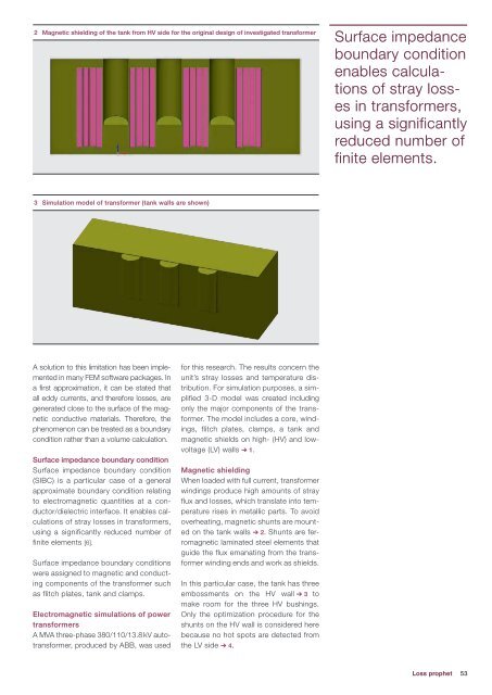
2 Magnetic shielding of the tank from HV side for the original design of investigated transformer<br />
Surface impedance<br />
boundary condition<br />
enables calculations<br />
of stray losses<br />
in transformers,<br />
using a significantly<br />
reduced number of<br />
finite elements.<br />
3 Simulation model of transformer (tank walls are shown)<br />
A solution to this limitation has been implemented<br />
in many FEM software packages. In<br />
a first approximation, it can be stated that<br />
all eddy currents, and therefore losses, are<br />
generated close to the surface of the magnetic<br />
conductive materials. Therefore, the<br />
phenomenon can be treated as a boundary<br />
condition rather than a volume calculation.<br />
Surface impedance boundary condition<br />
Surface impedance boundary condition<br />
(SIBC) is a particular case of a general<br />
approximate boundary condition relating<br />
to electromagnetic quantities at a conductor/dielectric<br />
interface. It enables calculations<br />
of stray losses in transformers,<br />
using a significantly reduced number of<br />
finite elements [6].<br />
Surface impedance boundary conditions<br />
were assigned to magnetic and conducting<br />
components of the transformer such<br />
as flitch plates, tank and clamps.<br />
Electromagnetic simulations of power<br />
transformers<br />
A MVA three-phase 380/110/13.8 kV autotransformer,<br />
produced by ABB, was used<br />
for this research. The results concern the<br />
unit’s stray losses and temperature distribution.<br />
For simulation purposes, a simplified<br />
3-D model was created including<br />
only the major components of the transformer.<br />
The model includes a core, windings,<br />
flitch plates, clamps, a tank and<br />
magnetic shields on high- (HV) and lowvoltage<br />
(LV) walls ➔ 1.<br />
Magnetic shielding<br />
When loaded with full current, transformer<br />
windings produce high amounts of stray<br />
flux and losses, which translate into temperature<br />
rises in metallic parts. To avoid<br />
overheating, magnetic shunts are mounted<br />
on the tank walls ➔ 2. Shunts are ferromagnetic<br />
laminated steel elements that<br />
guide the flux emanating from the transformer<br />
winding ends and work as shields.<br />
In this particular case, the tank has three<br />
embossments on the HV wall ➔ 3 to<br />
make room for the three HV bushings.<br />
Only the optimization procedure for the<br />
shunts on the HV wall is considered here<br />
because no hot spots are detected from<br />
the LV side ➔ 4.<br />
Loss prophet<br />
53