

review
aS45307enPA
aS45307enPA

You also want an ePaper? Increase the reach of your titles
YUMPU automatically turns print PDFs into web optimized ePapers that Google loves.
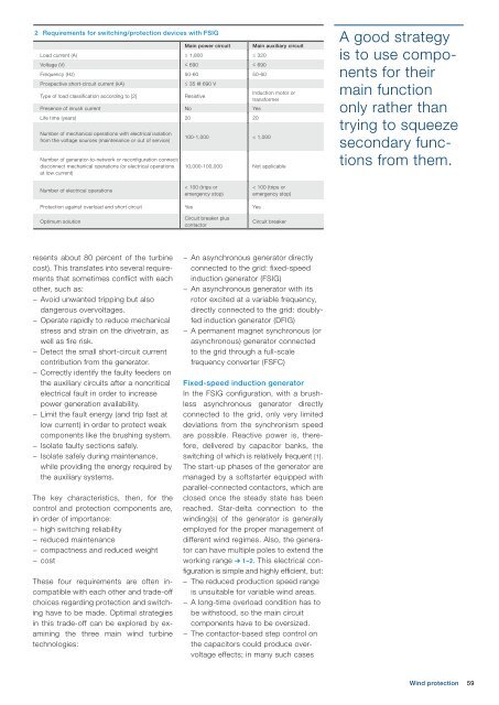
2 Requirements for switching/protection devices with FSIG<br />
Main power circuit Main auxiliary circuit<br />
Load current (A) ≤ 1,800 ≤ 320<br />
Voltage (V) ≤ 690 ≤ 690<br />
Frequency (Hz) 50-60 50-60<br />
Prospective short-circuit current (kA)<br />
≤ 35 @ 690 V<br />
Type of load classification according to [2]<br />
Resistive<br />
Induction motor or<br />
transformer<br />
Presence of inrush current No Yes<br />
Life time (years) 20 20<br />
Number of mechanical operations with electrical isolation<br />
from the voltage sources (maintenance or out of service)<br />
Number of generator-to-network or reconfiguration connect/<br />
disconnect mechanical operations (or electrical operations<br />
at low current)<br />
100-1,000 < 1,000<br />
10,000-100,000 Not applicable<br />
A good strategy<br />
is to use components<br />
for their<br />
main function<br />
only rather than<br />
trying to squeeze<br />
secondary functions<br />
from them.<br />
Number of electrical operations<br />
< 100 (trips or<br />
emergency stop)<br />
< 100 (trips or<br />
emergency stop)<br />
Protection against overload and short circuit Yes Yes<br />
Optimum solution<br />
Circuit breaker plus<br />
contactor<br />
Circuit breaker<br />
resents about 80 percent of the turbine<br />
cost). This translates into several requirements<br />
that sometimes conflict with each<br />
other, such as:<br />
− Avoid unwanted tripping but also<br />
dangerous overvoltages.<br />
− Operate rapidly to reduce mechanical<br />
stress and strain on the drivetrain, as<br />
well as fire risk.<br />
− Detect the small short-circuit current<br />
contribution from the generator.<br />
− Correctly identify the faulty feeders on<br />
the auxiliary circuits after a noncritical<br />
electrical fault in order to increase<br />
power generation availability.<br />
− Limit the fault energy (and trip fast at<br />
low current) in order to protect weak<br />
components like the brushing system.<br />
− Isolate faulty sections safely.<br />
− Isolate safely during maintenance,<br />
while providing the energy required by<br />
the auxiliary systems.<br />
The key characteristics, then, for the<br />
control and protection components are,<br />
in order of importance:<br />
− high switching reliability<br />
− reduced maintenance<br />
− compactness and reduced weight<br />
− cost<br />
These four requirements are often incompatible<br />
with each other and trade-off<br />
choices regarding protection and switching<br />
have to be made. Optimal strategies<br />
in this trade-off can be explored by examining<br />
the three main wind turbine<br />
technologies:<br />
− An asynchronous generator directly<br />
connected to the grid: fixed-speed<br />
induction generator (FSIG)<br />
− An asynchronous generator with its<br />
rotor excited at a variable frequency,<br />
directly connected to the grid: doublyfed<br />
induction generator (DFIG)<br />
− A permanent magnet synchronous (or<br />
asynchronous) generator connected<br />
to the grid through a full-scale<br />
frequency converter (FSFC)<br />
Fixed-speed induction generator<br />
In the FSIG configuration, with a brushless<br />
asynchronous generator directly<br />
connected to the grid, only very limited<br />
deviations from the synchronism speed<br />
are possible. Reactive power is, therefore,<br />
delivered by capacitor banks, the<br />
switching of which is relatively frequent [1].<br />
The start-up phases of the generator are<br />
managed by a softstarter equipped with<br />
parallel-connected contactors, which are<br />
closed once the steady state has been<br />
reached. Star-delta connection to the<br />
winding(s) of the generator is generally<br />
employed for the proper management of<br />
different wind regimes. Also, the generator<br />
can have multiple poles to extend the<br />
working range ➔ 1–2. This electrical configuration<br />
is simple and highly efficient, but:<br />
– The reduced production speed range<br />
is unsuitable for variable wind areas.<br />
− A long-time overload condition has to<br />
be withstood, so the main circuit<br />
components have to be oversized.<br />
− The contactor-based step control on<br />
the capacitors could produce overvoltage<br />
effects; in many such cases<br />
Wind protection<br />
59