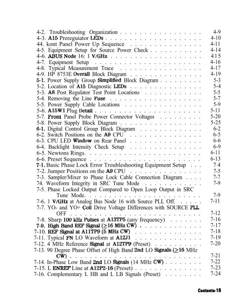
- Page 1 and 2: Errata Title & Document Type: 8753E
- Page 3 and 4: HP part number: 08753-90374 Superse
- Page 5 and 6: The BP BASIC Programming Examples G
- Page 7 and 8: Contents-2 In Case of DifficuIty .
- Page 9 and 10: 2a. 2b. 3. Contents4 In Case of Dif
- Page 11 and 12: Step 3. HP-IB Systems Check . . . .
- Page 13 and 14: 7. Source Troubleshooting Assembly
- Page 15 and 16: External Tests . . . . . . . . . .
- Page 17 and 18: Contents-12 A9 CPU/A10 Digital IF .
- Page 19 and 20: Contents-14 Removal . . . . . . . .
- Page 21 and 22: 15. Safety and Licensing Notice . .
- Page 23: 2-33. Sll l-Port Cal Test Setup . .
- Page 27 and 28: Tables l-l. Required Tools . . . .
- Page 29 and 30: ‘able 1-2. Service lkst Equipment
- Page 31 and 32: pestid Equipment Antistatic wrist B
- Page 33 and 34: ‘Ihble 1-3. Connector Care Quick
- Page 35 and 36: Option 075, 7563 Impedance This opt
- Page 37 and 38: System Verification and Performance
- Page 39 and 40: Note Calibration kits are different
- Page 41 and 42: Sections in This Chapter � System
- Page 43 and 44: System Verification Cycle and Kit R
- Page 45 and 46: Initialization 1. Clear all interna
- Page 47 and 48: 8. If you have difficulty with the
- Page 49 and 50: The analyzer briefly displays COMPU
- Page 51 and 52: H P 8753E NETWORK ANALYZER “ERlFl
- Page 53 and 54: In Case of Difiblty 1. Inspect alI
- Page 55 and 56: 1. Connect the equipment as shown i
- Page 57 and 58: 2. External Source Mode Frequency R
- Page 59: In Case of Difkulty If the analyzer
- Page 62 and 63: 3. Press-. Note The factory preset
- Page 64 and 65: 1. Zero and calibrate the power met
- Page 66 and 67: 2. Verify that there is power comin
- Page 68 and 69: H P 8753E NETWORK ANALYZER I Q m ,
- Page 70 and 71: 2-34 System Verification and Perfor
- Page 72 and 73: H P 8753E NETWORK ANALYZER - 24-INC
- Page 74 and 75:
Port 1 Noise Floor Level from 300 k
- Page 76 and 77:
Port 2 Noise Floor Level from 300 k
- Page 78 and 79:
ln Case of Difficulty 1. Perform th
- Page 80 and 81:
Power Meter Calibration for Test Po
- Page 84 and 85:
Power Meter Calibration on Port 2 f
- Page 86 and 87:
H P 8753E NETWORK ANALYZER HP 8753F
- Page 89 and 90:
Test Port 2 Input Frequency Respons
- Page 91 and 92:
,.,.. . . . . .,. .,. / . . . . 2.
- Page 93 and 94:
W32, Figure 2-26. HP 8753E Bottom V
- Page 95 and 96:
First Full 2-Port Calibration 1. Co
- Page 97:
Directivity (Forward) Calibration C
- Page 101 and 102:
10. System Trace Noise (Only for An
- Page 103 and 104:
System Trace Noise for B/R Phase 17
- Page 105 and 106:
. . . . 3. ~~~~ (m)~~~~~~~.~~, ~~~~
- Page 107 and 108:
System Trace Noise for B/R Phase fr
- Page 109 and 110:
1. Connect the equipment as shown i
- Page 111 and 112:
HP 8753E NETWORK ANALYZER - PORT 1
- Page 113 and 114:
13. ‘Ikst Port Receiver Magnitude
- Page 115 and 116:
Initial Calculations 1. Fill in the
- Page 117 and 118:
110 dB STEP ATTENUATOR HP 8753E NET
- Page 119 and 120:
Adapter Removal Calibration 13. Con
- Page 121 and 122:
Measure Test Port 2 Magnitude Dynam
- Page 123 and 124:
Measure Test Port 1 Magnitude Dynam
- Page 125:
14. T&t Port Receiver Magnitude Com
- Page 128 and 129:
15. Test Port Receiver Phase Compre
- Page 130 and 131:
lkst Port 1 Phase Compression . . .
- Page 132 and 133:
Test Port Output Worst Case 2nd Har
- Page 135 and 136:
Port 1 Input Worst Case 3rd Harmoni
- Page 137 and 138:
17. ‘I&t Port Output/Input Harmon
- Page 139 and 140:
Test Port Output Worst Case 3rd Har
- Page 141 and 142:
Port 1 Input Worst Case 3rd Harmoni
- Page 143 and 144:
18. ‘Ikst Port Output Harmonics (
- Page 145 and 146:
HP 8753E NETWORK ANALYZER PORT 1 *D
- Page 147 and 148:
6. Set up the network unuZ@zr to ou
- Page 149 and 150:
HP 8753E Performance Test Record (1
- Page 151 and 152:
EIP 8753E Performance ‘Jkst Recor
- Page 153 and 154:
HP 8753E Performance ‘l&t Record
- Page 155 and 156:
Hewlett-Packard Compnny Model HP 87
- Page 157 and 158:
HP 8753E Performance ‘I&t Record
- Page 159 and 160:
HP 8753E Performance lkst Record (1
- Page 161 and 162:
HP 8753E Option 011 Performance lks
- Page 163 and 164:
HP 8753E Performance ‘I&t Record
- Page 165 and 166:
HP 8753E Performance ‘l&t I&cord
- Page 167 and 168:
HP 8753E Performance ‘l&t Record
- Page 169 and 170:
I I J3P 8753E Performance ‘Best R
- Page 171 and 172:
HP 8753E Performance ‘Ikst Record
- Page 173 and 174:
HP 8753E Performance lkst Record (1
- Page 175 and 176:
HP 8753E Performance ‘l&t Record
- Page 177 and 178:
HP 8753E Performance ‘l&t Record
- Page 179 and 180:
Post-Repair Procedures for HP 8753E
- Page 181 and 182:
l&placed Al9fU?mbly Al3 Fractional-
- Page 183 and 184:
sga me A9 CPU Assembly Normal Mode
- Page 185 and 186:
Source Pretune Default Correction C
- Page 187 and 188:
Source Pretune Correction Constants
- Page 189 and 190:
Power Sensor Calibration Factor Ent
- Page 191 and 192:
HP 4388 POWER METER HP 438A POWER M
- Page 193 and 194:
IF Amplifier Correction Constants (
- Page 195 and 196:
Sampler Magnitude and Phase Correct
- Page 197:
7. For Option 006 Instruments Only:
- Page 200 and 201:
. . _ . . . _ . . _ .., _ 13. Press
- Page 202 and 203:
21. 22. 23. 24. . . ; ::.... :: . .
- Page 204 and 205:
f. Repeat the “Sampler Correction
- Page 206 and 207:
Perform the first five steps of the
- Page 208 and 209:
7. Observe the analyzer for the res
- Page 210 and 211:
CENTER 2 983.000 000 MHz SPAN 5.000
- Page 212 and 213:
6. Observe the analyzer for the res
- Page 214 and 215:
Initialize EEPROMs (T&t 58) This se
- Page 216 and 217:
5. Write the following information
- Page 218 and 219:
Loading Firmware Required Equipment
- Page 220 and 221:
Loading Firmware into a New CPU Use
- Page 223 and 224:
sg640e FN VCO ADJ ADJUSTMENT HOLE F
- Page 225 and 226:
Frequency Accuracy Adjustment Requi
- Page 227 and 228:
5- On the HP 8753E, press @GZj @GG)
- Page 229 and 230:
High/Low Band Transition Adjustment
- Page 231 and 232:
Fractional-N Spur Avoidance and FM
- Page 233 and 234:
4. On the HP 8753E, press LPreset]
- Page 235 and 236:
Source Spur Avoidance Tracking Adju
- Page 237 and 238:
Unprotected Hardware Option Numbers
- Page 239 and 240:
Sequences for Mechanical Adjustment
- Page 241 and 242:
� Refer to Chapter 7, “Source T
- Page 243 and 244:
SCALELREF REF VALUE 7 xl Sequences
- Page 245 and 246:
Start Troubleshooting Here The info
- Page 247 and 248:
Step 1. InitiaI Observations Initia
- Page 249 and 250:
4. Press ~E@WTE ‘EST to begin the
- Page 251 and 252:
If Using a Plotter or Printer 1. En
- Page 253 and 254:
Step 4. Faulty Group Isolation Use
- Page 255 and 256:
Digital Control Observe the Power U
- Page 258 and 259:
HP 8753E NETWORK ANALYZER / \ ADAPT
- Page 260:
Receiver Observe the A and B Input
- Page 264 and 265:
Power Supply Troubleshooting Use th
- Page 266 and 267:
Simplified Block Diagram Figure 5-l
- Page 268 and 269:
Check the Green LEDs on A8 Remove t
- Page 270 and 271:
If the Green LED of the Al5 Is not
- Page 272 and 273:
Al5 Al5Wl (To Pre Reguloiur A17J2 M
- Page 274 and 275:
&T REGULATOR BOARD SOLDER s, DE ::I
- Page 276 and 277:
Check the Operating Temperature The
- Page 278 and 279:
If the green LEDs are now on, the A
- Page 280 and 281:
� Make a list of these assemblies
- Page 282 and 283:
Error Messages Three error messages
- Page 284 and 285:
If the + 15 V and -12.6 V green LED
- Page 286:
Intermittent Problems PRESET states
- Page 289 and 290:
Digital Control Group Block Diagram
- Page 291 and 292:
CPU Troubleshooting (A9) A9 CC Swit
- Page 293 and 294:
LCPU LED WlNDOW Figure 6-3. CPU LED
- Page 295 and 296:
Backlight Intensity Check Required
- Page 297 and 298:
Dark Pixels Specidications Dark “
- Page 299 and 300:
Troubleshooting a White Display If
- Page 301 and 302:
Identify the Stuck Key Match the LE
- Page 303 and 304:
Inspect Cables Remove the front pan
- Page 305 and 306:
0Allrnt 1 Preset 2IwM lkst 3CMosRAM
- Page 307 and 308:
Source Troubleshooting Use this pro
- Page 310 and 311:
Phase Lock Error sg652e GIGITIZING
- Page 312 and 313:
. . . . . . . 2. ‘Jet& on the and
- Page 314 and 315:
A3 Source and A11 Phase Lock Check
- Page 316:
7- Press IMenu) ~~hkd# to vary the
- Page 319 and 320:
Al2 Reference Check The signals are
- Page 321 and 322:
Oscilloscope Method You need not us
- Page 323 and 324:
PLREF Waveforms REF Signal At AllTP
- Page 325 and 326:
FN LO at Al2 Check 1. Use an oscill
- Page 327 and 328:
2ND LO Waveforms The 2nd LO signals
- Page 329 and 330:
Al2 Digital Control Signals Check S
- Page 331 and 332:
‘Jhble 7-5. VC0 Range Check Frequ
- Page 333 and 334:
-50.000 n-w 0.00000 eec SO.000 “.
- Page 335 and 336:
Al4 Divide-by-N Circuit Check Note
- Page 337 and 338:
H MB Line. This signal is active du
- Page 339 and 340:
I I I I I I I CENTER 2.989 88 GClL
- Page 341 and 342:
‘Ihble 7-7. 1st IF Waveform Setti
- Page 343 and 344:
ti . I . L. I I I I t ’ II I 0.00
- Page 345 and 346:
Phase Lock Diagnostic Routines Perf
- Page 347 and 348:
Assembly Replacement Sequence The f
- Page 349 and 350:
Check the A and B Inputs Good input
- Page 351 and 352:
Troubleshooting When All Inputs Loo
- Page 353 and 354:
Check A10 by Substitution or Signal
- Page 355 and 356:
* DIF DATA consists of 16 serial bi
- Page 358 and 359:
If the trace shows no improvement w
- Page 360 and 361:
Accessories Troubleshooting Use thi
- Page 362 and 363:
Inspect the Accessories Inspect the
- Page 364 and 365:
Cable Test The load match error ter
- Page 366 and 367:
Figure 9-2. Typical Smith Chart Tra
- Page 368 and 369:
Service Key Menus - Internal Diagno
- Page 370 and 371:
‘Ihble 10-l shows the test status
- Page 372 and 373:
accesses the power loss/sensor list
- Page 374 and 375:
3 SRAM RAM. Verifies the A9 CPU SRA
- Page 376 and 377:
15 Frac N Cont. Tests the ability o
- Page 378 and 379:
System Verification Tests These tes
- Page 380 and 381:
55 Serial Cor. Stores the serial nu
- Page 382 and 383:
Test Patterns Test patterns are use
- Page 384 and 385:
Service Key Menus - Service Feature
- Page 386 and 387:
..,.,, _ _ _ . . . . . . . _.;.:..;
- Page 388 and 389:
Analog Bus Description of the Analo
- Page 390 and 391:
Analog In Menu Select this menu to
- Page 392 and 393:
Analog Bus Nodes The following para
- Page 394 and 395:
Node 2 Src lV/GHz (source 1 volt pe
- Page 396 and 397:
Node 4 Det (detects RF OUT power le
- Page 398 and 399:
Node 7 Log (log ampliiier output de
- Page 400 and 401:
Node 11 Aux Input (rear panel input
- Page 402 and 403:
Node 15 Pretune (open-loop source p
- Page 404 and 405:
Node 17 1st IF (IF used for phase l
- Page 406 and 407:
Node 20 IF Det 1 (IF after 30 MHz f
- Page 408 and 409:
Node 24 2nd LO perform step A12 ad
- Page 410 and 411:
Node 29 FN VU3 Tun (Al4 FN VCO tuni
- Page 412 and 413:
PEEK/POKE Menu m acceSS tl& menu, p
- Page 414 and 415:
HP-IB Service Mnemonic Definitions
- Page 416 and 417:
Error Messages This section contain
- Page 418 and 419:
DEVICE:noton,notconnect, wrong addr
- Page 420 and 421:
NO FILE(S) FOUND ONDISK Error Numbe
- Page 422 and 423:
PARALLEL PORT NOT AVAILABLE FOR COP
- Page 424 and 425:
POWER UNLEVELED Error Number There
- Page 426 and 427:
SWEEP MODE CHANGED TO CW TIME SWEEP
- Page 428 and 429:
connector and cable wear, or gradua
- Page 430 and 431:
FOR I SOLAT ION HP 8753E NETWORK AN
- Page 433 and 434:
The analyzer displays the corrected
- Page 435 and 436:
If Error Terms Seem Worse than Typi
- Page 437 and 438:
Directivity (EDF and EDR) Descripti
- Page 439 and 440:
Reflection Tracking (ERF and ERR) D
- Page 441 and 442:
Load Match (ELF and ELR) Descriptio
- Page 443 and 444:
Theory of Operation This chapter is
- Page 445 and 446:
The Built-In lkst Set The HP 8753E
- Page 447 and 448:
Power Supply Theory The power suppl
- Page 449 and 450:
A8 Post Regulator The A8 post regul
- Page 451 and 452:
L-_--I 7 --_ ( IT Pie 12-3. Digital
- Page 453 and 454:
The main CPU has a dedicated flash
- Page 455 and 456:
10 MHZ PRECISION REFERENCE. (Option
- Page 457 and 458:
A7 Pulse Generator A step recovery
- Page 459 and 460:
6. A synthesized sub sweep is gener
- Page 461 and 462:
Source High Band Operation The high
- Page 463 and 464:
lhble 12-3. High Band Subsweep Freq
- Page 465 and 466:
A13/14 FRACTIONAL-N A12 REFERENCE @
- Page 467 and 468:
Tuned Receiver Mode In tuned receiv
- Page 469 and 470:
FROM A3 A24 TRANSFER SW I TCH FRONT
- Page 471 and 472:
A4/AS/A6 Sampler/Mixer The A4, A5,
- Page 473 and 474:
Replaceable Parts This chapter cont
- Page 475 and 476:
Rebuilt-Exchange Assemblies Under t
- Page 477 and 478:
Replaceable Part Listings The follo
- Page 479 and 480:
A15\ A20 - A4' A10 A8 All A12 Major
- Page 481 and 482:
CPU Fan\ A24, Ai A23 A21 Major Asse
- Page 483 and 484:
w4 ’ w3 ’ w2 ’ w5 ’ W6 ’
- Page 485 and 486:
w32, w33' W38 \ I I A22kl ill AilWl
- Page 487 and 488:
w22 / W23 I AIWI \ RPGIWI hbles, Fr
- Page 489 and 490:
i w30 \ ’ w21 W36 \ w35 Cables, R
- Page 491 and 492:
A3A4Wl BACK I A3W3 A3W4 \ FRONT Cab
- Page 493 and 494:
Front Panel Assembly, Outside sg663
- Page 495 and 496:
(4 Places) Front Panel Assembly, In
- Page 497 and 498:
(8 Places) 9 15 13 0 PART OF FAN es
- Page 499 and 500:
Rear Panel Assembly, Option lD5 sg6
- Page 501 and 502:
(4 Places) (2 Places) (6 Places) \
- Page 503 and 504:
sgbb0e (L Places) (3 Places) 6 (2 P
- Page 505 and 506:
sg669e Hardware, Front I2 Places) R
- Page 507 and 508:
(5 Places) Hardware, ‘l&t Set Dec
- Page 509 and 510:
(4 Places) Q G--,, (4 Places) Hardw
- Page 511 and 512:
Replaceable Partr 1339
- Page 513 and 514:
IL- Hardware, Preregulator Al5 sg67
- Page 515 and 516:
(4 Places) (4 Places) (Underside) 0
- Page 517 and 518:
Chassis Parts, Inside (16 Places) s
- Page 519 and 520:
FXMALEIiHBCONNFXXUR PEMALETBTSETI/O
- Page 521 and 522:
14 Assembly Replacement and Post-Re
- Page 523 and 524:
Procedures described in this chapte
- Page 525 and 526:
FUSE IN USE ‘INSERT SCREWDRIVER,
- Page 527 and 528:
Covers sg677e Assambly Replacement
- Page 529 and 530:
Front Pctnel Assembly Asssmbly Repl
- Page 531 and 532:
Front Panel Keyboard and Interface
- Page 533 and 534:
Replacement 1. Reverse the order of
- Page 535 and 536:
Rear Panel Assembly Tools Required
- Page 537 and 538:
Rear Panel Assembly 14-18 Assembly
- Page 539 and 540:
(7 (2 (Opt ID5 only) Rear Panel Int
- Page 541 and 542:
W2L W26 w1 - , AwnMy Replacclment s
- Page 543 and 544:
A4, AS, A6 Samplers and A7 Pulse Ge
- Page 545 and 546:
A4, A5, A6 Samplers and A7 Pulse Ge
- Page 547 and 548:
AS, AlO, All, A12, A13, Al4 Caxd Ca
- Page 549 and 550:
w37 w20 \ A9 CPU Board sg6112e Asse
- Page 551 and 552:
A9BTl Battery Tools Required � T-
- Page 553 and 554:
A15 Preregulator Tools Required �
- Page 555 and 556:
Al7 Motherboard Assembly Tools Requ
- Page 557 and 558:
A 17 Motherboard Assembly lb remove
- Page 559 and 560:
A19 Graphics Processor Tools Requir
- Page 561 and 562:
A20 Disk Drive Assembly Tools Requi
- Page 563 and 564:
A20 Disk Drive Assembly Install the
- Page 565 and 566:
A21, A22 Test Port Couplers Tools R
- Page 567 and 568:
A23 LED Board Tools Required � T-
- Page 569 and 570:
A24 Transfer Switch Tools Required
- Page 571 and 572:
A25 Test Set Interface Tools Requir
- Page 573 and 574:
A26 High Stability Frequency Refere
- Page 575 and 576:
Bl Fan Assembly Tools Required �
- Page 577 and 578:
Post-Repair Procedures for HP 8753E
- Page 579 and 580:
gepLacea As!3embly Al3 Fractional-N
- Page 581 and 582:
Warranty This Hewlett-Packard instr
- Page 583 and 584:
Shipment for Service If you are sen
- Page 585 and 586:
Safety Considerations Note This ins
- Page 587 and 588:
General Warning ‘Ib prevent elect
- Page 589 and 590:
Index 1 100 kHz pulses, 7-16 10 MHz
- Page 591 and 592:
adjustment A9 Switch Positions, 3-5
- Page 593 and 594:
transfer switch, 12-26 bus analog,
- Page 595 and 596:
CURRENT PARAMETER NOT IN CAL SET, l
- Page 597 and 598:
INSUFFICIENT MEMORY, PWR MTR CAL OF
- Page 599 and 600:
G good trace display, 8-5 green LED
- Page 601 and 602:
tool, l-3 verification kit 7 mm, l-
- Page 603 and 604:
NO PHASE LOCK CHECK R INPUT LEVEL,
- Page 605 and 606:
part numbers, 13-26 prereguiated vo
- Page 607 and 608:
hardware, test set deck, 13-34 hard
- Page 609 and 610:
SOURCE POWER TURNED OFF, RESET UNDE
- Page 611 and 612:
theory of operation, 12-3 transfer


