PCAN-MIO - User Manual - PEAK-System
PCAN-MIO - User Manual - PEAK-System
PCAN-MIO - User Manual - PEAK-System

You also want an ePaper? Increase the reach of your titles
YUMPU automatically turns print PDFs into web optimized ePapers that Google loves.
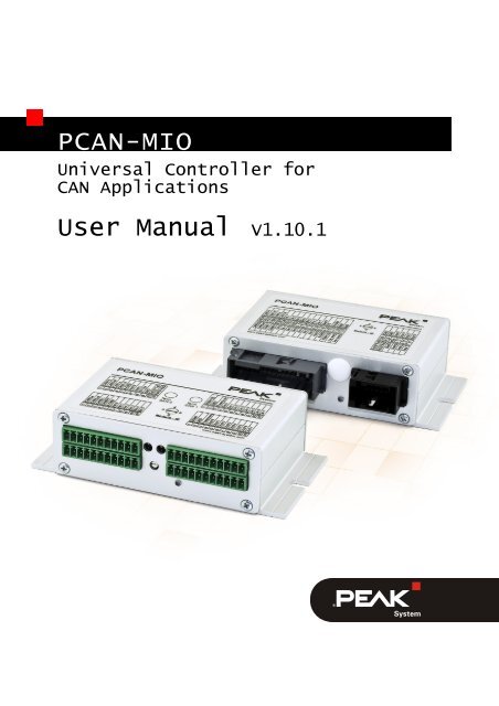
<strong>PCAN</strong>-<strong>MIO</strong><br />
Universal Controller for<br />
CAN Applications<br />
<strong>User</strong> <strong>Manual</strong> V1.10.1
<strong>PCAN</strong>-<strong>MIO</strong> – <strong>User</strong> <strong>Manual</strong><br />
Products taken into account<br />
Product Name Model Part number<br />
<strong>PCAN</strong>-<strong>MIO</strong> Industrial plug connector (Phoenix) IPEH-002187<br />
<strong>PCAN</strong>-<strong>MIO</strong> Automotive plug connector (Tyco) IPEH-002187-A<br />
Product names mentioned in this manual may be the trademarks or registered trademarks<br />
of their respective companies. They are not explicitly marked by Ҡand “®â€.<br />
© 2012 <strong>PEAK</strong>-<strong>System</strong> Technik GmbH<br />
<strong>PEAK</strong>-<strong>System</strong> Technik GmbH<br />
Otto-Roehm-Strasse 69<br />
64293 Darmstadt<br />
Germany<br />
Phone: +49 (0)6151 8173-20<br />
Fax: +49 (0)6151 8173-29<br />
www.peak-system.com<br />
info@peak-system.com<br />
Document version 1.10.1 (2012-08-08)<br />
2
<strong>PCAN</strong>-<strong>MIO</strong> – <strong>User</strong> <strong>Manual</strong><br />
Contents<br />
1 Introduction 5<br />
1.1 Properties at a Glance 6<br />
1.2 Prerequisites for Operation 7<br />
1.3 Scope of Supply 7<br />
2 Function Characteristics of the Basic Module 8<br />
2.1 Supply 8<br />
2.2 Analog Inputs 9<br />
2.3 Analog Outputs 9<br />
2.4 Digital Inputs 10<br />
2.5 Digital Outputs 10<br />
2.6 Function Blocks 11<br />
2.7 P<strong>PCAN</strong> Protocol 12<br />
2.8 Module Reset 12<br />
3 Operation 13<br />
3.1 Module Settings 13<br />
3.2 Basic Connections 15<br />
3.3 Output States at Power-up 16<br />
3.4 Software Installation 16<br />
3.5 Altered Configuration Structure from Serial<br />
Number 100 18<br />
4 Front Panel Elements 20<br />
4.1 Pin Assignment 20<br />
4.1.1 Industrial Connector (Phoenix) 20<br />
4.1.2 Automotive Connector (Tyco) 23<br />
4.2 CAN Bus Termination (Switch) 25<br />
4.3 Module ID (Rotary Switch) 26<br />
4.4 Status LED 27<br />
3
<strong>PCAN</strong>-<strong>MIO</strong> – <strong>User</strong> <strong>Manual</strong><br />
5 Alternative CAN Transceiver Modules 28<br />
6 Technical Specifications 30<br />
Appendix A CE Certificate 32<br />
Appendix B Dimension Drawings 33<br />
Appendix C Module Resources 35<br />
4
<strong>PCAN</strong>-<strong>MIO</strong> – <strong>User</strong> <strong>Manual</strong><br />
1 Introduction<br />
The Multiple Input Output module (<strong>MIO</strong>) is supplied as a universal,<br />
modular control unit in the mid-range performance class. It is designed<br />
to be used in both industrial and automotive applications.<br />
The basic module provides a mixed analog and digital functionality.<br />
A bus structure also permits adding modules to expand the number<br />
of inputs and outputs. This permits implementing individual customer<br />
requirements. As many as six additional modules are possible<br />
(Modifications of the housing and the front plate are generally<br />
necessary).<br />
Signals and data can be modified and linked by the microcontroller<br />
in a wide variety of ways. A large number of what is referred to as<br />
function blocks are available (see section 2.6 on page 11).<br />
The inputs and outputs, i.e., the behavior of the <strong>PCAN</strong>-<strong>MIO</strong> module<br />
can be configured using software which runs on the Windows<br />
operating system. A configuration from the PC to the <strong>PCAN</strong>-<strong>MIO</strong><br />
module is transmitted via a CAN bus.<br />
The <strong>PCAN</strong>-<strong>MIO</strong> module has two CAN channels, which can be adapted<br />
with internal plug-in modules (transceivers) to various physical<br />
CAN transmission standards. Between the two CAN channels it is<br />
possible for CAN messages to be exchanged via the gateway<br />
function.<br />
The basic module is combined with a vertically arranged connector<br />
board and an all-metal housing. As an option a top hat rail mounting<br />
is also possible. An alternative connector board enables inputs<br />
and outputs of the basic module to be adapted to specific target<br />
system requirements.<br />
5
<strong>PCAN</strong>-<strong>MIO</strong> – <strong>User</strong> <strong>Manual</strong><br />
1.1 Properties at a Glance<br />
8 digital inputs with low-pass performance<br />
8 digital outputs, 2 of which PWM-capable<br />
6 analog inputs (10 bit, 0 - 10 V)<br />
2 analog outputs (10 bit, 0 - 10 V)<br />
2 High-speed CAN channels via plug-in transceiver modules<br />
(wake-up capable); optionally available are modules for Lowspeed,<br />
Single-wire, opto-decoupled High-speed, and High-speed<br />
without wake-up function<br />
CAN termination can be activated by DIP switches<br />
CAN gateway between the buses<br />
Configuration with the supplied Windows software P<strong>PCAN</strong>-<br />
Editor 2<br />
Module can store up to 15 configurations<br />
Various function blocks for data linking and modification<br />
Industrial connectors with spring terminals (Phoenix), optionally<br />
available with automotive connectors (Tyco)<br />
Voltage supply 9 - 30 V, overvoltage and reversed polarity<br />
protection<br />
Wake-up function via separate input or via the CAN bus<br />
Aluminum profile casing with mounting flange<br />
Option for mounting on top hat rails<br />
Extended operating temperature range of -40 to +85 °C (-40 to<br />
+185 °F)<br />
6
<strong>PCAN</strong>-<strong>MIO</strong> – <strong>User</strong> <strong>Manual</strong><br />
1.2 Prerequisites for Operation<br />
Power source, nominal 12 V, 9 - 30 V possible<br />
For configuring via CAN:<br />
• Computer with CAN interface of the <strong>PCAN</strong> series (<strong>PCAN</strong>-<br />
USB is part of the optionally available Set)<br />
• CAN cabling with correct termination<br />
• Windows 7/Vista/XP (32/64-bit) for the configuration<br />
program<br />
1.3 Scope of Supply<br />
<strong>PCAN</strong>-<strong>MIO</strong> basic module in a all-metal housing<br />
4 terminal strip plugs (industrial model IPEH-002187)<br />
32-pole and 12-pole plug with crimp contacts (automotive model<br />
IPEH-002187-A)<br />
Configuration software P<strong>PCAN</strong>-Editor 2 for Windows<br />
Documentation in PDF format<br />
CAN interface <strong>PCAN</strong>-USB with order of the Set<br />
7
<strong>PCAN</strong>-<strong>MIO</strong> – <strong>User</strong> <strong>Manual</strong><br />
2 Function Characteristics of<br />
the Basic Module<br />
This chapter describes the essential functional characteristics of the<br />
<strong>PCAN</strong>-<strong>MIO</strong> basic module.<br />
There is a list of all logical resources (I/O function, I/O number)<br />
which are provided by the <strong>PCAN</strong>-<strong>MIO</strong> module in the Appendix C on<br />
page 35.<br />
2.1 Supply<br />
The internal 5-Volt supply is provided by a switching regulator. This<br />
regulator also meets the 5-Volt needs of additional boards and<br />
external low-power consumers such as sensors. The dimensioning<br />
covers an overall need of 2 A.<br />
At the power input protection is provided against overvoltage and<br />
reversed polarity. With the help of two internal control lines the<br />
microcontroller can switch internal consumers on or off and activate<br />
self-holding. To handle brownouts, a comparator checks the internal<br />
5-Volt supply and triggers a reset if necessary (smaller than 4.35 V).<br />
The CAN transceiver modules are wake-up-capable and are permanently<br />
supplied with input voltage.<br />
The <strong>PCAN</strong>-<strong>MIO</strong> module can be activated by an external control<br />
connection as an alternative to the CAN wake-up. After booting, the<br />
microcontroller itself can control the power supply by means of the<br />
mentioned self-holding. External sensors are supplied with 5 V,<br />
protected and loadable to a max. of 500 mA. In case of a shortcircuit<br />
the continued work of the microcontroller is assured by the<br />
decoupling of the internal 5-Volt supply. A reference of 5 V is<br />
provided for analog, internal use.<br />
8
<strong>PCAN</strong>-<strong>MIO</strong> – <strong>User</strong> <strong>Manual</strong><br />
2.2 Analog Inputs<br />
There are six analog inputs with high-ohm pull-down circuit<br />
(100 kΩ), low-pass performance, and overvoltage protection. The<br />
standard measurement range is from 0 to 10 V. Analog measurements<br />
are unipolar, single-ended, have a resolution of 10 bit (A/D<br />
converter) and are referenced to 5 V with 0.2 % accuracy and a<br />
temperature coefficient of 20 ppm.<br />
The measurement range for the individual inputs can be adapted by<br />
a voltage divider. Regarding this subject please contact <strong>PEAK</strong>-<br />
<strong>System</strong> (contact information: see on page 2).<br />
2.3 Analog Outputs<br />
The two analog outputs are derived from a 10-bit D/A converter. The<br />
standard output voltage is 0 to 10 V for a maximum current drain of<br />
20 mA. The outputs are short-circuit-proof. As an option, instead of<br />
the internal reference of 5 V, the supply voltage VE can be specified<br />
as a reference (hardware modification required). In this case, the<br />
internal reference is 1/3 of the supply voltage VE, however, it is<br />
limited to 5.1 V.<br />
The internal reference is used as a standard. Regarding the optional<br />
external reference please contact <strong>PEAK</strong>-<strong>System</strong> (contact information:<br />
see on page 2).<br />
9
<strong>PCAN</strong>-<strong>MIO</strong> – <strong>User</strong> <strong>Manual</strong><br />
2.4 Digital Inputs<br />
There are eight digital inputs with low-pass performance and hysteresis<br />
behavior. In groups with one, two or three inputs, at the inputs<br />
DIN0 to DIN5, pull-down resistors can be connected, for example for<br />
contacts. At the DIN6 and DIN7 inputs only one pull-up circuit is<br />
available.<br />
The switch thresholds are 4 V (High) and 3 V (Low). For the powersave<br />
mode the pull-up circuits can be shut down by the microcontroller.<br />
The inputs DIN0 to DIN4 are connected directly to the inputcapture<br />
pins of the microcontroller as fast inputs to determine frequencies<br />
and the duty cycles. The DIN5 to DIN7 inputs are for the<br />
static status recognition (max. possible switching frequency:<br />
approx. 1 kHz).<br />
2.5 Digital Outputs<br />
The eight digital outputs are subdivided into six protected, statically<br />
addressable low-power switches (DOUT2 to DOUT7, max. 0.6 A)<br />
and two protected, PWM-capable high-side switches (DOUT0 and<br />
DOUT1, max. 1.4 A). The high-side switches are allocated to PWMcapable<br />
timer outputs (HW-PWM). In the case of the low-power<br />
switches, a configuration can be used to decide for each output<br />
whether it should work as high-side or low-side switch or be inactive.<br />
When used as low-side switch, an output can be operated with<br />
up to 30 V against ground.<br />
The protective measures relate to excessive voltage, current, and<br />
temperature. The high-side switch is supplied with power directly<br />
from the module's power connection. Protection is provided against<br />
reverse poling of the supply voltage.<br />
10
<strong>PCAN</strong>-<strong>MIO</strong> – <strong>User</strong> <strong>Manual</strong><br />
2.6 Function Blocks<br />
This table is an overview of the various function blocks available for<br />
processing the data with the microcontroller.<br />
You can obtain details about the individual function blocks from the<br />
reference tables which come with the configuration program<br />
P<strong>PCAN</strong>-Editor for Windows which is included in the delivery.<br />
Function block Description<br />
Identity Copies the input variable to the output variable.<br />
Scaling Conversion of an input value, with multiplicators and offset;<br />
the result is copied into the output variable.<br />
Hysteresis The output is dependent on the input value set to one of<br />
two pre-defined values.<br />
Monoflop The output is set to one of two pre-defined values depending<br />
on the input value for a pre-defined period.<br />
Extended Hysteresis Depending on an input value the output is timeout activated<br />
for a pre-defined period (set to 1). A second input acts<br />
as an enable signal.<br />
Switch Delay Switch-on, switch-off delay or a combination of the two.<br />
Lowpass Realization of a lag element by a low-pass with an adjustable<br />
time.<br />
Characteristic Curve The input signal is converted by applying a pre-defined<br />
characteristic curve.<br />
Characteristic Curve Like the characteristic curve but in this case values speci-<br />
with Limit<br />
fied outside the characteristic curve are returned.<br />
Characteristic Map The input signal is converted using a pre-defined surface<br />
which is composed from a list of characteristic curves.<br />
Characteristic Map Like the characteristic map but in this case values speci-<br />
with Limit<br />
fied outside the surface are returned.<br />
Small Map The two inputs indicate a position within a grid of 12<br />
fields. The return values of the fields are specified by the<br />
default assignment tables.<br />
Ramp Counter Each time a function is called the counter counts one<br />
more step from a lower to an upper limit and then begins<br />
again at the lower value.<br />
Counter with Clock Counter for flanks to an input<br />
and Reload Input<br />
11
<strong>PCAN</strong>-<strong>MIO</strong> – <strong>User</strong> <strong>Manual</strong><br />
Function block Description<br />
PI Element Simple PI regulator with reference and actual value inputs<br />
PIDT1 Element PIDT1 regulator<br />
Difference Help function block for the PIDT1 regulator<br />
Math Function Collection of various mathematical and logical functions<br />
Binary Field Compiles a sequence of digital data into a binary value.<br />
2.7 P<strong>PCAN</strong> Protocol<br />
The <strong>PCAN</strong>-<strong>MIO</strong> module is configured via a connected CAN bus per<br />
P<strong>PCAN</strong> protocol (point-to-point CAN), a development achieved by<br />
<strong>PEAK</strong>-<strong>System</strong> Technik GmbH. The P<strong>PCAN</strong> protocol permits as a<br />
principle the data communication between two specified CAN<br />
nodes, i.e., CAN data are transmitted to a specific target. In this way<br />
configuration data transmissions can be directed to one P<strong>PCAN</strong>capable<br />
module or to a transmitted <strong>PCAN</strong>-<strong>MIO</strong> module on the CAN<br />
bus.<br />
Note: The P<strong>PCAN</strong> protocol uses the CAN ID 7E7h for communication.<br />
Do not use this CAN ID for further communication of<br />
CAN nodes in a net.<br />
2.8 Module Reset<br />
The module has no separate switch or input for a reset. You can<br />
reset the <strong>PCAN</strong>-<strong>MIO</strong> module by separating it for a short time from<br />
the supply. An option for switching off, for example, is the selfhold<br />
function controlled via CAN, the subsequent restart can be triggered<br />
by a wake-up signal.<br />
12
<strong>PCAN</strong>-<strong>MIO</strong> – <strong>User</strong> <strong>Manual</strong><br />
3 Operation<br />
This chapter describes the preparations necessary to ensure that the<br />
<strong>PCAN</strong>-<strong>MIO</strong> module can receive and transmit data via a connected<br />
CAN bus. This section does not yet discuss how to create and apply<br />
a configuration. There is a guide on this subject in the help pages<br />
provided with the Windows-based P<strong>PCAN</strong>-Editor.<br />
The description assumes that you initially connect only one <strong>PCAN</strong>-<br />
<strong>MIO</strong> module via a High-speed CAN bus to a PC with a Windows<br />
operating system.<br />
Please read through all the sections in this chapter.<br />
3.1 Module Settings<br />
Settings for the module ID and a CAN termination can be made<br />
using switches on the <strong>PCAN</strong>-<strong>MIO</strong> module.<br />
Please check that the rotary switch for the Module ID is set to 0.<br />
Rotary switch for the module ID on the front plate of the industrial model<br />
13
<strong>PCAN</strong>-<strong>MIO</strong> – <strong>User</strong> <strong>Manual</strong><br />
Rotary switch for the module ID<br />
on the front plate of the automotive model<br />
Since in the assumed case the <strong>PCAN</strong>-<strong>MIO</strong> module is the sole node<br />
on the High-speed CAN bus connected via a direct line to the CAN<br />
interface of a PC, the termination must be activated. The two DIP<br />
switches on the switch block for CAN 0 must be in the upper<br />
position ON.<br />
Switch blocks for the CAN bus termination<br />
on the front plate of the industrial model<br />
Switch blocks for the CAN bus termination (automotive model),<br />
rear side of the connector board when the <strong>PCAN</strong>-<strong>MIO</strong> housing is open<br />
14
<strong>PCAN</strong>-<strong>MIO</strong> – <strong>User</strong> <strong>Manual</strong><br />
3.2 Basic Connections<br />
Connector pin assignment industrial model<br />
Connector pin assignment automotive model<br />
The following pins are used to connect the CAN bus:<br />
Line Connection<br />
Industrial<br />
Connection<br />
Automotive<br />
CAN0_L B1/B3 A14/A16<br />
CAN0_H B2/B4 A13/A15<br />
Comment<br />
Ports with the same signal name are<br />
internally connected.<br />
The operation of the <strong>PCAN</strong>-<strong>MIO</strong> module requires a voltage source<br />
with a nominal 12 V direct current voltage (9 - 30 V possible). The<br />
connection is made using these pins:<br />
Line Connection<br />
Industrial<br />
GND C2/D2 A17/A18<br />
VE C3/D3 A1/A2<br />
Connection Comment<br />
Automotive<br />
Ports with the same signal name are<br />
internally connected.<br />
When supply voltage is present, the module starts operation only<br />
on a wake-up signal. Depending on the CAN transceiver equipment<br />
15
<strong>PCAN</strong>-<strong>MIO</strong> – <strong>User</strong> <strong>Manual</strong><br />
this happens automatically, or you have to apply a High stage to the<br />
external wake-up line.<br />
Line Connection<br />
Industrial<br />
Connection<br />
Automotive<br />
WAKE-UP C1 A3<br />
The <strong>PCAN</strong>-<strong>MIO</strong> module has started operation when the status LED<br />
blinks green.<br />
3.3 Output States at Power-up<br />
After powering up the module and before a configuration is read<br />
from the EEPROM the outputs have the following states:<br />
Outputs State<br />
DOUT high impedance (tri-state)<br />
AOUT 0 V<br />
5V-OUT high impedance (tri-state)<br />
3.4 Software Installation<br />
The module is configured using the included P<strong>PCAN</strong>-Editor, which<br />
runs on a Windows platform, via a CAN bus connection between<br />
the computer and the <strong>PCAN</strong>-<strong>MIO</strong> module.<br />
This is how to install the P<strong>PCAN</strong>-Editor:<br />
1. Only Windows XP: Make sure that you are logged in as user<br />
with administrator privileges.<br />
When you use the P<strong>PCAN</strong>-Editor later you can also work as<br />
a user with limited rights.<br />
16
<strong>PCAN</strong>-<strong>MIO</strong> – <strong>User</strong> <strong>Manual</strong><br />
2. Start the setup program from the supplied CD, directory<br />
Tools/P<strong>PCAN</strong>-Editor.<br />
Startup screen of the installation program for the P<strong>PCAN</strong>-Editor<br />
3. Follow the instructions of the setup program until you come<br />
to the step Select Hardware Profiles. At this point select at<br />
least both entries for the <strong>PCAN</strong>-<strong>MIO</strong> module so that it will be<br />
supported by the P<strong>PCAN</strong>-Editor.<br />
Selection of the hardware profile for the <strong>PCAN</strong>-<strong>MIO</strong> module<br />
17
<strong>PCAN</strong>-<strong>MIO</strong> – <strong>User</strong> <strong>Manual</strong><br />
4. Follow the remaining instructions of the setup program.<br />
You can then launch the P<strong>PCAN</strong>-Editor, create a configuration, and<br />
transmit this to the <strong>PCAN</strong>-<strong>MIO</strong> module. Find relevant information in<br />
the help of the P<strong>PCAN</strong>-Editor. See also some introductory video<br />
tutorials to the P<strong>PCAN</strong>-Editor in the Support area on our website<br />
(www.peak-system.com).<br />
Note: The P<strong>PCAN</strong>-Editor uses the CAN ID 7E7h for communication<br />
with the <strong>PCAN</strong>-<strong>MIO</strong> module. Do not use this CAN ID for<br />
further communication of CAN nodes in a net.<br />
3.5 Altered Configuration Structure from<br />
Serial Number 100<br />
From serial number 100 <strong>PCAN</strong>-<strong>MIO</strong> modules work with an internally<br />
altered configuration structure. Therefore, at creation of a new configuration<br />
in the P<strong>PCAN</strong>-Editor you must select the appropriate<br />
hardware profile:<br />
<strong>PCAN</strong>-<strong>MIO</strong> serial<br />
number<br />
<strong>MIO</strong> hardware profile<br />
to be used<br />
up to 99 <strong>PCAN</strong>-<strong>MIO</strong><br />
from 100 <strong>PCAN</strong>-<strong>MIO</strong> (32-Bit)<br />
Configurations being created based on the other <strong>MIO</strong> hardware<br />
profile cannot be directly sent to a <strong>PCAN</strong>-<strong>MIO</strong> module.<br />
Do the following to adapt a configuration to another <strong>MIO</strong><br />
hardware profile:<br />
1. In the P<strong>PCAN</strong>-Editor open the present <strong>MIO</strong> configuration.<br />
2. Select the menu command Edit > New Configuration.<br />
The window for selecting a hardware profile is shown.<br />
18
<strong>PCAN</strong>-<strong>MIO</strong> – <strong>User</strong> <strong>Manual</strong><br />
3. Depending on the <strong>MIO</strong> hardware profile used presently select<br />
the other one. When updating to a <strong>PCAN</strong>-<strong>MIO</strong> module<br />
with serial number 100 and up, this is $1B <strong>PCAN</strong>-<strong>MIO</strong> (32-<br />
Bit), in the vice versa case accordingly $14 <strong>PCAN</strong>-<strong>MIO</strong>.<br />
4. Create the module-specific CAN configuration on the new<br />
tab in the window CAN Objects. This is done on basis of the<br />
General CAN objects. When matching the entries, you can<br />
use the previous module-specific CAN configuration for<br />
orientation.<br />
5. Open the configuration windows of the previous and the<br />
new configuration (Config XY).<br />
6. From each tab of the present configuration, copy all entries<br />
onto the tab of the new one. You can use the known key<br />
shortcuts for selecting, copying, and inserting under<br />
Windows.<br />
7. In the CAN Objects window, delete the former configuration<br />
by executing the corresponding context menu command on<br />
the configuration's tab.<br />
Note: New I/O functions which are only available in the hardware<br />
profile “$1B <strong>PCAN</strong>-<strong>MIO</strong> (32-Bit)†cannot be copied to configurations<br />
based on the profile “$14 <strong>PCAN</strong>-<strong>MIO</strong>â€.<br />
19
<strong>PCAN</strong>-<strong>MIO</strong> – <strong>User</strong> <strong>Manual</strong><br />
4 Front Panel Elements<br />
This chapter describes the elements present on the front of the<br />
<strong>PCAN</strong>-<strong>MIO</strong> module housing. They involve connections, the switches<br />
for the CAN bus termination, the rotary switch to set the module ID<br />
and the status LED.<br />
If you use an alternative plug-in board with a modified front panel,<br />
the elements may be different from the standard elements mentioned<br />
here.<br />
4.1 Pin Assignment<br />
This section describes the functional assignment of all pin connections.<br />
There is a list of all logical resources (I/O function, I/O number)<br />
which are provided by the <strong>PCAN</strong>-<strong>MIO</strong> module in the Appendix<br />
C on page 35.<br />
Ports with the same signal name are internally connected.<br />
4.1.1 Industrial Connector (Phoenix)<br />
Connector pin assignment of the industrial model<br />
20
<strong>PCAN</strong>-<strong>MIO</strong> – <strong>User</strong> <strong>Manual</strong><br />
Name Use More info<br />
A<br />
1 CAN1_L<br />
Connected to pin 3; at Singlewire<br />
CAN not connected<br />
2<br />
3<br />
CAN1_H<br />
CAN1_L<br />
CAN connection transceiver 1<br />
Connected to pin 4<br />
Connected to pin 1; at Singlewire<br />
CAN not connected<br />
4 CAN1_H<br />
Connected to pin 2<br />
5 AGND<br />
Ground analog, reference for<br />
AOUT and AIN<br />
6<br />
7<br />
AOUT0<br />
AOUT1<br />
Analog Output<br />
0 - 10 V, 20 mA, 10 bit<br />
Only source<br />
8 5V-OUT 5 V, 500 mA<br />
9 GND<br />
Ground, reference for digital<br />
and power supply<br />
10<br />
11<br />
B<br />
TXD<br />
RXD<br />
RS-232<br />
1 CAN0_L<br />
Connected to pin 3; at Singlewire<br />
CAN not connected<br />
2<br />
3<br />
CAN0_H<br />
CAN0_L<br />
CAN connection transceiver 0<br />
Connected to pin 4<br />
Connected to pin 1; at Singlewire<br />
CAN not connected<br />
4 CAN0_H<br />
Connected to pin 2<br />
5 AGND<br />
Ground analog, reference for<br />
AOUT and AIN<br />
6 AIN0<br />
7 AIN1<br />
8<br />
9<br />
AIN2<br />
AIN3<br />
Analog input 0 - 10 V 13.6 kΩ input impedance<br />
10 AIN4<br />
11 AIN5<br />
21
<strong>PCAN</strong>-<strong>MIO</strong> – <strong>User</strong> <strong>Manual</strong><br />
Name Use More info<br />
C<br />
1 WAKE-UP Digital input for wake-up signal High (> 4.0 V) = module on<br />
2 GND<br />
Ground, reference for digital<br />
and power supply<br />
3 VE Power supply 9 - 30 V DC<br />
4 DIN0<br />
High > 4.0 V, Low < 3.0 V<br />
5<br />
6<br />
DIN1<br />
DIN2<br />
Digital input, optional<br />
determination of frequencies<br />
5 - 10,000 Hz<br />
Pull-up/Pull-down:<br />
up to ser. no. 99 by jumpers<br />
7 DIN3 and duty cycles<br />
on the board (on request),<br />
8 DIN4<br />
from ser. no. 100 by<br />
configuration<br />
9<br />
10<br />
DIN5<br />
DIN6<br />
Digital input (static status<br />
detection)<br />
Max. processible switch<br />
frequency < 500 Hz<br />
11<br />
D<br />
DIN7<br />
1 Shield Shield<br />
2 GND<br />
Ground, reference for digital<br />
and power supply<br />
3 VE Power supply 9 - 30 V DC<br />
4 DOUT0 Digital output, high-side driver Optional FOUT/PWM OUT<br />
5 DOUT1 5 A short circuit<br />
with maximum frequency<br />
6 DOUT2<br />
7 DOUT3<br />
Useable as high-side, low-<br />
8<br />
9<br />
DOUT4<br />
DOUT5<br />
Digital output<br />
0.6 A each<br />
1.4 A together<br />
side, or push-pull driver (by<br />
configuration)<br />
Low-side: max. 30 V against<br />
10 DOUT6<br />
GND<br />
11 DOUT7<br />
22
<strong>PCAN</strong>-<strong>MIO</strong> – <strong>User</strong> <strong>Manual</strong><br />
4.1.2 Automotive Connector (Tyco)<br />
Connector pin assignment of the automotive model<br />
Name Use More info<br />
A<br />
1<br />
2<br />
VE Power supply 12 V DC KL30<br />
17<br />
18<br />
GND<br />
Ground, reference for digital<br />
and power supply<br />
KL31<br />
3 WAKE-UP Digital input for wake-up signal High (> 4.0 V) = module on<br />
19 5V-OUT 5 V, 500 mA<br />
4 AGND<br />
Ground analog, reference for<br />
AOUT and AIN<br />
20 P0 Reserved<br />
5<br />
21<br />
AOUT0<br />
AOUT1<br />
Analog Output<br />
0 - 10 V, 20 mA, 10 bit<br />
Only source<br />
6 AIN0<br />
Pull-down circuit 100 kΩ,<br />
optional pull-up circuit to 5V-<br />
22 AIN1<br />
OUT<br />
7 AIN2 Analog input 0 - 10 V<br />
23<br />
8<br />
AIN3<br />
AIN4<br />
Pull-down circuit 100 kΩ<br />
24 AIN5<br />
9 DIN0<br />
High > 4.0 V, Low < 3.0 V<br />
25<br />
10<br />
DIN1<br />
DIN2<br />
Digital input, optional determination<br />
of frequencies and duty<br />
5 - 10,000 Hz<br />
Pull-up/Pull-down:<br />
up to ser. no. 99 by jumpers<br />
26 DIN3 cycles<br />
on the board (on request),<br />
11 DIN4<br />
from ser. no. 100 by configuration<br />
23
<strong>PCAN</strong>-<strong>MIO</strong> – <strong>User</strong> <strong>Manual</strong><br />
Name Use More info<br />
27<br />
12<br />
DIN5<br />
DIN6<br />
Digital input (static status<br />
detection)<br />
Max. processible switch frequency<br />
< 500 Hz<br />
28 DIN7<br />
13 CAN0_H Connected to pin 15<br />
Connected to pin 16; at<br />
14 CAN0_L<br />
Single-wire CAN not<br />
15 CAN0_H<br />
CAN connection transceiver 0<br />
connected<br />
Connected to pin 13<br />
Connected to pin 14; at<br />
16 CAN0_L<br />
Single-wire CAN not<br />
connected<br />
29 CAN1_H Connected to pin 31<br />
Connected to pin 32; at<br />
30 CAN1_L<br />
Single-wire CAN not<br />
31 CAN1_H<br />
CAN connection transceiver 1<br />
connected<br />
Connected to pin 29<br />
Connected to pin 30; at<br />
32<br />
B<br />
CAN1_L<br />
Single-wire CAN not<br />
connected<br />
1 DOUT0 Digital output, high-side driver Optional FOUT/PWM OUT<br />
7 DOUT1 5 A short circuit<br />
with maximum frequency<br />
2 DOUT2<br />
8 DOUT3<br />
Useable as high-side, low-<br />
3<br />
9<br />
DOUT4<br />
DOUT5<br />
Digital output<br />
0.6 A each<br />
1.4 A together<br />
side, or push-pull driver (by<br />
configuration)<br />
Low-side: max. 30 V against<br />
4 DOUT6<br />
GND<br />
10 DOUT7<br />
5<br />
6<br />
GND<br />
Ground, reference for digital<br />
and power supply<br />
KL31<br />
11<br />
12<br />
RxD<br />
TxD<br />
RS-232<br />
24
<strong>PCAN</strong>-<strong>MIO</strong> – <strong>User</strong> <strong>Manual</strong><br />
4.2 CAN Bus Termination (Switch)<br />
Depending on the used CAN transceiver module you can activate or<br />
change a CAN bus termination with the corresponding switch<br />
blocks. Switches 1 and 2 on a switch block always must have the<br />
same position. By default the switches are in OFF position (lower<br />
position according to the orientation of the figure). The assignment<br />
of switch block to CAN channel is visible from the respective<br />
labeling (CAN channels CAN0 and CAN1).<br />
Switch blocks for the CAN bus termination (industrial model)<br />
Switch blocks for the CAN bus termination (automotive model),<br />
rear side of the connector board when the <strong>PCAN</strong>-<strong>MIO</strong> housing is open<br />
Type of transceiver<br />
Termination at switch position *<br />
OFF (standard) ON<br />
High-speed CAN (ISO 11898-2) none 120 Ω between<br />
CAN_L and CAN_H<br />
Low-speed CAN (ISO 11898-3) 4.7 kΩ for<br />
1.1 kΩ for<br />
CAN_L and CAN_H CAN_L and CAN_H<br />
Single-wire CAN (SAE J2411) 9.1 kΩ for CAN_SW 2.1 kΩ for CAN_SW<br />
* Both switches of a switch block<br />
25
<strong>PCAN</strong>-<strong>MIO</strong> – <strong>User</strong> <strong>Manual</strong><br />
4.3 Module ID (Rotary Switch)<br />
The rotary switch has 16 rest positions to determine the module ID<br />
(0 - F hex = 0 - 15). The position for ID 0 is to the left. The model IDs<br />
increase in a clockwise direction.<br />
Rotary switch for the module ID (industrial model)<br />
Rotary switch for the module ID (automotive model),<br />
remove cover plug if present<br />
When the <strong>PCAN</strong>-<strong>MIO</strong> module is started the configuration with the<br />
number from the internal memory is loaded which matches the<br />
specified module ID (from ser. no. 100 excluding module ID 15). In<br />
addition, with the module ID there is a unique identification of the<br />
<strong>PCAN</strong>-<strong>MIO</strong> module during the P<strong>PCAN</strong> communication<br />
(configuration transfer). For the transmission of CAN messages in<br />
normal operation this module ID is not relevant.<br />
From serial number 100 the module ID 15 is reserved for the case of<br />
a firmware update failure so that there's still a possibility to access<br />
the <strong>PCAN</strong>-<strong>MIO</strong> module. At this setting a CAN bootloader is ready<br />
after a module reset. See also the separate documentation for a<br />
firmware update via CAN (on request).<br />
26
<strong>PCAN</strong>-<strong>MIO</strong> – <strong>User</strong> <strong>Manual</strong><br />
This is how you change the module ID of a <strong>PCAN</strong>-<strong>MIO</strong> module:<br />
1. Change the position of the rotary switch with a small slot<br />
screwdriver.<br />
2. Restart the module by briefly interrupting the power supply.<br />
After the restart the changed module ID will be active.<br />
Before the restart changes made at the rotary switch will<br />
have no influence on operation.<br />
Tip: If the communication with the <strong>PCAN</strong>-<strong>MIO</strong> module is<br />
prevented because you do not know the bit rates used by the<br />
CAN channels, you can set the module ID to a position without<br />
configuration. In this case the respective standard bit rate is<br />
active for each equipped CAN transceiver (see following<br />
chapter 5 on page 28).<br />
4.4 Status LED<br />
The status LED being located on the lower right of the front panel<br />
indicates the current operation status of the <strong>PCAN</strong>-<strong>MIO</strong> module by<br />
different colors and blinking frequencies.<br />
Color Blinking<br />
frequency<br />
Operational status of the module<br />
Red Briefly on Initialization of the module (power-on self test, POST)<br />
Permanently on Hardware defect<br />
Green 1 Hz (slow) Normal operation with the configuration which is<br />
allocated to the currently specified module ID<br />
2 Hz (fast) No or no valid configuration available for the currently<br />
specified module ID<br />
27
<strong>PCAN</strong>-<strong>MIO</strong> – <strong>User</strong> <strong>Manual</strong><br />
5 Alternative CAN Transceiver<br />
Modules<br />
The <strong>PCAN</strong>-<strong>MIO</strong> basic module comes equipped with High-speed<br />
CAN transceivers (from ser. no. 100 with wake-up function). On<br />
request, we can provide each CAN channel also with an alternative<br />
CAN transceiver module.<br />
The <strong>PCAN</strong>-<strong>MIO</strong> module automatically detects the CAN transceiver<br />
module in use and provides the according transfer parameters.<br />
<strong>PCAN</strong>-<strong>MIO</strong> PCB with plug-on transceiver modules<br />
28
<strong>PCAN</strong>-<strong>MIO</strong> – <strong>User</strong> <strong>Manual</strong><br />
Following CAN transceiver modules are available:<br />
Module name Transmission<br />
standard<br />
CAN-HS High-speed CAN<br />
ISO 11898-2<br />
CAN-HS opto High-speed CAN<br />
ISO 11898-2<br />
CAN-HS-1041<br />
(standard)<br />
High-speed CAN<br />
ISO 11898-2<br />
CAN-LS Low-speed CAN<br />
ISO 11898-3<br />
CAN-LS-SW Single-wire CAN<br />
SAE J2411<br />
Special function Standard bit<br />
rate<br />
500 kbit/s<br />
Galvanic isolation up to 300 V 500 kbit/s<br />
for the CAN interface<br />
Wake-up 500 kbit/s<br />
Wake-up 125 kbit/s<br />
Wake-up 33.3 kbit/s<br />
29
<strong>PCAN</strong>-<strong>MIO</strong> – <strong>User</strong> <strong>Manual</strong><br />
6 Technical Specifications<br />
Power supply<br />
Supply voltage 9 - 30 V DC<br />
Brownout check Reset if internal 5-Volt supply < 4.35 V<br />
Current consumption 60 mA typ. (without separate circuits)<br />
Reverse-polarity protection Yes<br />
Sensor power supply 5 V (max. -2 %), 500 mA<br />
Outputs<br />
Voltage sustaining capability DOUT2 - DOUT7: Low-side 30 V<br />
DOUT<br />
Continuous current DOUT DOUT0 - DOUT1: High-side 1.4 A<br />
DOUT2 - DOUT7: High-/Low-side 0.6 A per<br />
output (1.4 A together)<br />
Short-circuit current DOUT DOUT0 - DOUT1: 5 A<br />
DOUT2 - DOUT7: 1 A<br />
Frequency DOUT DOUT0 - DOUT1: 65 - 6,000 Hz<br />
Voltage AOUT 0 - 10 V, each 20 mA (for internal reference<br />
voltage), other voltage range on request<br />
Resolution AOUT 10 bit<br />
Inputs<br />
Switching thresholds DIN ON = 4 V, OFF = 3 V<br />
Frequency range DIN0 - DIN4 5 - 10,000 Hz<br />
Integration time constant AIN: 1.6 ms<br />
DIN: 23 μs<br />
Measurement range AIN 0 - 10 V, other measuring range on request<br />
Resolution AIN 10 bit<br />
Circuit AIN Pull-down 100 kΩ<br />
Input impedance AIN 13.6 kΩ<br />
Max. input voltage DIN/AIN 30 V<br />
Continued on the next page<br />
30
<strong>PCAN</strong>-<strong>MIO</strong> – <strong>User</strong> <strong>Manual</strong><br />
CAN<br />
Standard transceiver Up to ser. no. 99:<br />
High-speed CAN ISO 11898-2 (TJA1040)<br />
From ser. no. 100:<br />
High-speed CAN ISO 11898-2 with wake-up<br />
function (TJA1041)<br />
Other transceivers (on request) High-speed CAN ISO 11898-2 (TJA1040)<br />
with galvanic isolation<br />
Low-speed CAN ISO 11898-3 (TJA1054)<br />
with wake-up function<br />
Single-wire CAN SAE J2411 (TH8056)<br />
with wake-up function<br />
Wake-up time typically 200 ms<br />
(depending on the size of the configuration)<br />
Termination Setup with switches on the board<br />
CAN OFF ON<br />
High-speed none 120 Ω<br />
Low-speed 4.7 kΩ 1.1 kΩ<br />
Single-wire 9.1 kΩ 2.1 kΩ<br />
CAN ID reserved for<br />
configuration transfer<br />
7E7h<br />
Interference resistance<br />
Tests IEC 61000 and DIN EN 61326 compliant<br />
Peculiarity surge ±500 V<br />
Environment<br />
Operating temperature -40 - +85 °C (-40 - +185 °F)<br />
Temperature for storage and<br />
transport<br />
-40 - +100 °C (-40 - +212 °F)<br />
Relative humidity 15% - 90%, not condensing<br />
Ingress protection (IEC 60529) IP20<br />
Measures<br />
Size 130 x 65 x 35 mm (5 1/8 x 2 9/16 x 1 3/8 inches)<br />
(without plug)<br />
See also dimension drawings on page 33<br />
Weight max. 280 g (9.9 oz.)<br />
31
<strong>PCAN</strong>-<strong>MIO</strong> – <strong>User</strong> <strong>Manual</strong><br />
Appendix A CE Certificate<br />
32
<strong>PCAN</strong>-<strong>MIO</strong> – <strong>User</strong> <strong>Manual</strong><br />
Appendix B Dimension Drawings<br />
Continued on the next page<br />
Front of the industrial model<br />
Front of the automotive model<br />
33
<strong>PCAN</strong>-<strong>MIO</strong> – <strong>User</strong> <strong>Manual</strong><br />
Top view of the bottom plate<br />
The figures don’t show the original size.<br />
34
<strong>PCAN</strong>-<strong>MIO</strong> – <strong>User</strong> <strong>Manual</strong><br />
Appendix C Module Resources<br />
The table lists all the logical resources of the <strong>PCAN</strong>-<strong>MIO</strong> module, arranged by I/O functions (column “I/O Functionâ€) and the pertinent I/O numbers (column<br />
“I/O Numberâ€).<br />
I/O Function I/O Number Value range Connection Function<br />
DOut Level (00h)<br />
DOut Frequency (01h)<br />
DO H0 D4 High-side output 0<br />
DO H1 D5 High-side output 1<br />
DO H2 D6 High-side output 2<br />
DO H3<br />
DO H4<br />
0: open, 1: High<br />
D7<br />
D8<br />
High-side output 3<br />
High-side output 4<br />
DO H5 D9 High-side output 5<br />
DO H6 D10 High-side output 6<br />
DO H7<br />
D11 High-side output 7<br />
DO HL2 D6 Push-pull output 2<br />
DO HL3 D7 Push-pull output 3<br />
DO HL4<br />
DO HL5<br />
0: Low, 1: High<br />
D8<br />
D9<br />
Push-pull output 4<br />
Push-pull output 5<br />
DO HL6 D10 Push-pull output 6<br />
DO HL7<br />
D11 Push-pull output 7<br />
DO L2 D6 Low-side output 2<br />
DO L3 D7 Low-side output 3<br />
DO L4<br />
DO L5<br />
0: open, 1: Low<br />
D8<br />
D9<br />
Low-side output 4<br />
Low-side output 5<br />
DO L6 D10 Low-side output 6<br />
DO L7<br />
D11 Low-side output 7<br />
Freq 0 Up to ser. no. 99: 310 - 6000 D4 Frequency output 0<br />
Freq 1<br />
From ser. no. 100: 17 - 6000 D5 Frequency output 1<br />
35<br />
1.4 A<br />
0.6 A (1.4 A together)<br />
0.6 A (1.4 A together)<br />
0.6 A (1.4 A together)<br />
Generates a variable frequency signal with a configurable<br />
duty cycle (indication in Hz)
<strong>PCAN</strong>-<strong>MIO</strong> – <strong>User</strong> <strong>Manual</strong><br />
I/O Function I/O Number Value range Connection Function<br />
DOut Ratio (03h)<br />
AOut Level (10h)<br />
Special Out (70h)<br />
PWM 0 D4 PWM output 0<br />
0 - 255 (255 = 100 %)<br />
PWM 1<br />
D5 PWM output 1<br />
AOut 0 A6 Analog output 0<br />
0 - 1023 (1023 = 10 V)<br />
AOut 1<br />
A7 Analog output 1<br />
36<br />
Generates a PWM signal with variable duty cycle and<br />
configurable frequency<br />
10-bit D/A converter, Ia = 20 mA<br />
Enable 5V 0: Off, 1: On A8<br />
5-Volt supply for external sensor<br />
Ia = 200 mA<br />
Selfhold 0: Off, 1: On 1 at power-on. To switch off the module set to 0.<br />
Enable RS232 0: Off, 1: On<br />
1 at power-on. Switches the High stage for the pull-ups at the digital inputs, the reference voltage<br />
for analog in-/outputs, the RS-232 level converter.<br />
LED Pattern<br />
CAN_L: B1, B3<br />
(Reserved)<br />
CAN 0 Mode<br />
CAN_H: B2, B4<br />
Operation mode CAN transceiver 0<br />
0: Normal (all transceivers)<br />
1: WakeUp (AU5790)<br />
CAN 1 Mode<br />
0 - 5<br />
SW-CAN: B2, B4<br />
CAN-L: A1, A3<br />
CAN-H: A2, A4<br />
SW-CAN: A2, A4<br />
Operation mode CAN transceiver 1<br />
2: PowerDown (AU7590, TJA1040, TJA1041, TJA1054)<br />
3: ListenOnly (TJA1040, TJA1041, TJA1054)<br />
4: HighSpeed (AU5790)<br />
5: Standby (TJA1040, TJA1041, TJA1054)<br />
Routing 0 to 1 all<br />
Routing 1 to 0 all<br />
0: Off, 1: On Forwarding of all CAN messages<br />
from bus 0 to bus 1<br />
from bus 1 to bus 0<br />
Not to be combined with<br />
explicit or excluding<br />
Debug Mode (Reserved)<br />
Routing 0 to 1 explicit<br />
Routing 1 to 0 explicit<br />
11-bit CAN ID,<br />
29-bit CAN ID<br />
Forward the specified 11-bit CAN ID<br />
from bus 0 to bus 1<br />
from bus 1 to bus 0<br />
Not to be combined with all<br />
or excluding<br />
Routing 0 to 1 excluding 11-bit CAN ID,<br />
Forwarding of all CAN messages except from bus 0 to bus 1 Not to be combined with all<br />
Routing 1 to 0 excluding 29-bit CAN ID<br />
the specified 11-bit CAN ID from bus 1 to bus 0 or explicit<br />
CAN 0 baud raw<br />
CAN 1 baud raw<br />
0x0000 - 0xFFFF Set the CAN baud rate by direct insertion of the register value into the baud rate register<br />
CAN 33.3 kBd<br />
CAN 47.6 kBd<br />
CAN 50 kBd<br />
CAN 83.3 kBd<br />
0, 1 (CAN channel) Specify a CAN baud rate
<strong>PCAN</strong>-<strong>MIO</strong> – <strong>User</strong> <strong>Manual</strong><br />
I/O Function I/O Number<br />
CAN 95.2 kBd<br />
CAN 100 kBd<br />
CAN 125 kBd<br />
CAN 250 kBd<br />
CAN 500 kBd<br />
CAN 1 MBd<br />
Value range Connection Function<br />
DIn Level (80h)<br />
DIn Frequency (81h)<br />
DIn Ratio (83h)<br />
Pull-Up/Down (88h)<br />
Level 0 C4 Digital input 0<br />
Level 1 C5 Digital input 1<br />
Level 2 C6 Digital input 2<br />
Level 3 0: Low<br />
C7 Digital input 3<br />
Level 4 1: High<br />
C8 Digital input 4<br />
Level 5 C9 Digital input 5<br />
Level 6 C10 Digital input 6<br />
Level 7<br />
C11 Digital input 7<br />
Freq 0 C4 Frequency input 0<br />
Freq 1 C5 Frequency input 1<br />
Freq 2 5 - 10000 (Hz)<br />
C6 Frequency input 2<br />
Freq 3 C7 Frequency input 3<br />
Freq 4<br />
C8 Frequency input 4<br />
Ratio 0 C4 PWM input 0<br />
Ratio 1 C5 PWM input 1<br />
Ratio 2 0 - 1000 (1000 = 100% high) C6 PWM input 2<br />
Ratio 3 C7 PWM input 3<br />
Ratio 4<br />
C8 PWM input 4<br />
Pull-Up 0; 1-3; 4; 5-7<br />
Pull-Dn 0; 1-3; 4; 5-7<br />
0: deactivated<br />
1: activated<br />
C4…C11<br />
37<br />
Vih = 4 V<br />
Vil = 3 V<br />
Frequency measurement<br />
Vih = 4 V<br />
Vil = 3 V<br />
Pull-up resistor for digital input or digital input<br />
group<br />
Pull-down resistor for digital input or digital<br />
input group<br />
Measurement of the duty cycle (high phase)<br />
Vih = 4 V<br />
Vil = 3 V<br />
(only to 1 kHz)<br />
Pull-up/pull-down resistors each 4.7 kΩ.<br />
This I/O function is only available in the<br />
hardware profile “<strong>PCAN</strong>-<strong>MIO</strong> (32-Bit)†(from<br />
ser. no. 100).
<strong>PCAN</strong>-<strong>MIO</strong> – <strong>User</strong> <strong>Manual</strong><br />
I/O Function I/O Number Value range Connection Function<br />
AIn Level (90h)<br />
Tau (98h)<br />
Const (CCh)<br />
Positive Const (CDh)<br />
Negative Const (CEh)<br />
AIn 0 B6 Analog input 0<br />
AIn 1 B7 Analog input 1<br />
AIn 2<br />
AIn 3<br />
0 - 1023<br />
B8<br />
B9<br />
Analog input 2<br />
Analog input 3<br />
AIn 4 B10 Analog input 4<br />
AIn 5<br />
B11 Analog input 5<br />
Tau 0 Time constant for analog input 0<br />
Tau 1 Time constant for analog input 1<br />
Tau 2<br />
Tau 3<br />
0 - 60000 (ms)<br />
Time constant for analog input 2<br />
Time constant for analog input 3<br />
Tau 4 Time constant for analog input 4<br />
Tau 5<br />
Time constant for analog input 5<br />
(See list in the P<strong>PCAN</strong>-<br />
Editor)<br />
(Diverse values)<br />
0 to 255 (0 to +255)<br />
0 to -255 (0 to -255)<br />
Diverse constants<br />
Read only; can be used as input constants.<br />
Positive constants<br />
Read only; can be used as input constants.<br />
Negative constants<br />
Read only; can be used as input constants.<br />
38<br />
Input range: 0 - 10 V<br />
Hardware low-pass: 6.8 kΩ, 33 nF<br />
Software low-pass for analog inputs
<strong>PCAN</strong>-<strong>MIO</strong> – <strong>User</strong> <strong>Manual</strong><br />
I/O Function I/O Number Value range Connection Function<br />
Special In (F0h)<br />
32bit Variable (FFh)<br />
ConfVerMain 0 - 255<br />
ConfVerSub 0 - 255<br />
FW VerMain 0 - 7<br />
FW VerSub 0 - 31<br />
FW BuildNo 0 - 255<br />
Main version number of the<br />
configuration<br />
Secondary version number of the<br />
configuration<br />
Main version number of the<br />
firmware<br />
Secondary version number of the<br />
firmware<br />
Build version number of the<br />
firmware<br />
39<br />
Version of the configuration; can be specified in the P<strong>PCAN</strong>-<br />
Editor during the module-specific settings<br />
For information purposes; read only<br />
Module ID 0 - 15<br />
Module ID<br />
Position of the corresponding rotary switch on the <strong>PCAN</strong>-<strong>MIO</strong> module; ID must be unique within<br />
the CAN net.<br />
MainCycleCounter Count of computation cycles of the firmware since the last call; read only<br />
MainCycleTime Max 0 - 65535<br />
Maximum duration in ms for a computation cycle since the last call; read only<br />
MainCycleTime Avg<br />
Average duration in μs for a computation cycle since the last call; read only<br />
none<br />
No function<br />
Can be used as place-holder if the corresponding input or output has no function.<br />
0 to 255 32 Bit signed<br />
Internal 32-bit variable<br />
Temporary memory for values of function blocks and CAN variables
![English - Low Quality [7.2 MB] - PEAK-System](https://img.yumpu.com/5931738/1/184x260/english-low-quality-72-mb-peak-system.jpg?quality=85)