PCAN-PCI Express - User Manual - PEAK-System
PCAN-PCI Express - User Manual - PEAK-System
PCAN-PCI Express - User Manual - PEAK-System

You also want an ePaper? Increase the reach of your titles
YUMPU automatically turns print PDFs into web optimized ePapers that Google loves.
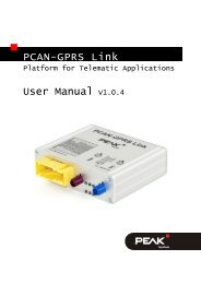
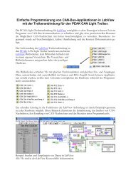
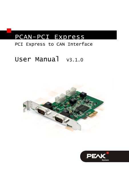
<strong>PCAN</strong>-<strong>PCI</strong> <strong>Express</strong><br />
<strong>PCI</strong> <strong>Express</strong> to CAN Interface<br />
<strong>User</strong> <strong>Manual</strong> V3.1.0
<strong>PCAN</strong>-<strong>PCI</strong> <strong>Express</strong> – <strong>User</strong> <strong>Manual</strong><br />
Products taken into account<br />
Product Name Model Part Number Ser. No.<br />
<strong>PCAN</strong>-<strong>PCI</strong> <strong>Express</strong> Single One CAN channel IPEH-003026<br />
Channel galv. isolated<br />
starting at<br />
<strong>PCAN</strong>-<strong>PCI</strong> <strong>Express</strong> Dual<br />
Channel galv. Isolated<br />
Two CAN channels IPEH-003027 01000<br />
<strong>PCAN</strong>-<strong>PCI</strong> <strong>Express</strong> Four<br />
Channel galv. isolated<br />
Four CAN channels IPEH-003040<br />
The cover picture shows the product <strong>PCAN</strong>-<strong>PCI</strong> <strong>Express</strong> Four Channel galvanic<br />
isolated. Other product versions have an identical form factor but vary in equipment.<br />
CANopen® and CiA® are registered community trade marks of CAN in Automation<br />
e.v.<br />
All other product names mentioned in this manual may be the trademarks or<br />
registered trademarks of their respective companies. They are not explicitly marked<br />
by “” and “®”.<br />
© 2012 <strong>PEAK</strong>-<strong>System</strong> Technik GmbH<br />
<strong>PEAK</strong>-<strong>System</strong> Technik GmbH<br />
Otto-Roehm-Strasse 69<br />
64293 Darmstadt<br />
Germany<br />
Phone: +49 (0)6151 8173-20<br />
Fax: +49 (0)6151 8173-29<br />
www.peak-system.com<br />
info@peak-system.com<br />
Document version 3.1.0 (2012-07-25)<br />
2
<strong>PCAN</strong>-<strong>PCI</strong> <strong>Express</strong> – <strong>User</strong> <strong>Manual</strong><br />
Contents<br />
1 Introduction 4<br />
1.1 Properties at a Glance 4<br />
1.2 <strong>System</strong> Requirements 5<br />
1.3 Scope of Supply 5<br />
2 Installing the Software and the Card 6<br />
3 Connecting the CAN Bus 9<br />
3.1 D-Sub connector 9<br />
3.2 Supplying External Devices via the CAN<br />
Connector 10<br />
3.3 Cabling 12<br />
3.3.1 Termination 12<br />
3.3.2 Example of a Connection 12<br />
3.3.3 Maximum Bus Length 13<br />
4 Using the Software 14<br />
4.1 CAN Monitor <strong>PCAN</strong>-View for Windows 14<br />
4.1.1 Receive/Transmit Tab 16<br />
4.1.2 Trace Tab 18<br />
4.1.3 Status Bar 19<br />
4.2 Linking Own Programs with <strong>PCAN</strong>-Basic 20<br />
4.2.1 Features of <strong>PCAN</strong>-Basic 21<br />
4.2.2 Principle Description of the API 22<br />
4.2.3 Notes about the License 23<br />
5 Technical Specifications 24<br />
Appendix A CE Certificate 26<br />
Appendix B Dimension Drawing 27<br />
Appendix C Quick Reference 28<br />
3
<strong>PCAN</strong>-<strong>PCI</strong> <strong>Express</strong> – <strong>User</strong> <strong>Manual</strong><br />
1 Introduction<br />
The <strong>PCAN</strong>-<strong>PCI</strong> <strong>Express</strong> card enables the connection of a PC with<br />
<strong>PCI</strong> <strong>Express</strong> slots to CAN networks. The card is available as a single,<br />
dual, or four-channel version. Device drivers and programming<br />
interfaces exist for different operating systems, so programs can<br />
easily access a connected CAN bus.<br />
Tip: At the end of this manual (Appendix C) you can find a<br />
Quick Reference with brief information about the installation<br />
and operation of the <strong>PCAN</strong>-<strong>PCI</strong> <strong>Express</strong> card.<br />
1.1 Properties at a Glance<br />
PC plug-in card (<strong>PCI</strong>e-x1) for <strong>PCI</strong> <strong>Express</strong> slots<br />
1, 2 or 4 High-speed CAN channels (ISO 11898-2)<br />
Bit rates up to 1 Mbit/s<br />
Compliant CAN specifications 2.0A (11-bit ID)<br />
and 2.0B (29-bit ID)<br />
CAN bus connection via D-Sub,<br />
9-pin (in accordance with CiA® 102)<br />
NXP SJA1000-compatible CAN controller<br />
(FPGA implementation)<br />
NXP PCA82C251 CAN transceiver<br />
Galvanic isolation on the CAN connection up to 500 V, separate<br />
for each CAN channel<br />
5-Volts supply to the CAN connection can be connected through<br />
a solder jumper, e.g. for external bus converter<br />
4
<strong>PCAN</strong>-<strong>PCI</strong> <strong>Express</strong> – <strong>User</strong> <strong>Manual</strong><br />
Extended operating temperature range from -40 to 85 °C<br />
(-40 to 185 °F)<br />
Note: This manual describes the use of the <strong>PCAN</strong>-<strong>PCI</strong> <strong>Express</strong><br />
card with Windows. You can find device drivers for Linux and<br />
the corresponding application information on the provided DVD<br />
in the directory branch Develop and on our website under<br />
www.peak-system.com/linux.<br />
1.2 <strong>System</strong> Requirements<br />
A vacant <strong>PCI</strong> <strong>Express</strong> slot in the computer<br />
Operating system Windows 7/Vista/XP (32/64-bit)<br />
or Linux (32/64-bit)<br />
1.3 Scope of Supply<br />
<strong>PCAN</strong>-<strong>PCI</strong> <strong>Express</strong> card<br />
Slot bracket with D-Sub connectors for the CAN bus (only fourchannel<br />
version)<br />
Device drivers for Windows 7/Vista/XP (32/64-bit)<br />
and Linux (32/64-bit)<br />
<strong>PCAN</strong>-View CAN monitor for Windows<br />
<strong>PCAN</strong>-Basic programming interface consisting of an interface<br />
DLL, examples, and header files for all common programming<br />
languages<br />
<strong>Manual</strong> in PDF format<br />
5
<strong>PCAN</strong>-<strong>PCI</strong> <strong>Express</strong> – <strong>User</strong> <strong>Manual</strong><br />
2 Installing the Software and<br />
the Card<br />
This chapter covers the software setup for the <strong>PCAN</strong>-<strong>PCI</strong> <strong>Express</strong><br />
card (short: <strong>PCI</strong>e card) under Windows and the installation of the<br />
card in the computer.<br />
Setup the driver before installing the <strong>PCI</strong>e card.<br />
Do the following to install the driver:<br />
1. Make sure that you are logged in as user with administrator<br />
privileges (not needed for normal use of the <strong>PCI</strong>e card later<br />
on).<br />
2. Insert the supplied DVD into the appropriate drive of the<br />
computer. Usually a navigation program appears a few<br />
moments later. If not, start the file Intro.exe from the root<br />
directory of the DVD.<br />
3. On the page English > Drivers activate the entry <strong>PCAN</strong>-<strong>PCI</strong>.<br />
4. Click on Install now. The setup program for the driver is<br />
executed.<br />
5. Follow the instructions of the setup program.<br />
Tip: If you don't want to install the CAN monitor <strong>PCAN</strong>-View for<br />
Windows onto the hard disk together with the driver, you have<br />
the option to start the program later directly from DVD without<br />
prior installation.<br />
6
<strong>PCAN</strong>-<strong>PCI</strong> <strong>Express</strong> – <strong>User</strong> <strong>Manual</strong><br />
Do the following to install the <strong>PCI</strong>e card into the computer:<br />
Attention! Electrostatic discharge (ESD) can damage or destroy<br />
components on the <strong>PCAN</strong>-<strong>PCI</strong> <strong>Express</strong> card. Take precautions<br />
to avoid ESD when handling the card.<br />
1. Four-channel version only: Connect the 10-pin connector of<br />
CAN ports 3 and 4 with a cable from the slot bracket.<br />
Figure 1: Position of the sockets for the CAN connection,<br />
CAN 3 (upper left position), CAN 4 (upper right position)<br />
2. Shut down the computer and switch it off.<br />
3. Disconnect the computer from the power supply.<br />
4. Open the computer's casing.<br />
5. If applicable, remove a front blind in front of the desired slot<br />
of the <strong>PCI</strong>e card. The additional slot bracket with connectors<br />
used by the four-channel version needs a further place.<br />
6. Insert the <strong>PCI</strong>e card into a vacant <strong>PCI</strong> <strong>Express</strong> slot. For<br />
details refer to the documentation of the computer.<br />
7. Close the computer's casing.<br />
8. Reconnect the power supply of the computer.<br />
7
<strong>PCAN</strong>-<strong>PCI</strong> <strong>Express</strong> – <strong>User</strong> <strong>Manual</strong><br />
Do the following to complete the initialization:<br />
1. Turn on the computer and start Windows. Make sure again<br />
that you are logged in as user with administrator privileges.<br />
Windows notifies that new hardware has been detected.<br />
2. Windows XP only: A Wizard dialog box appears. Follow its<br />
instructions. Deny the search for driver software at<br />
Windows update and select the automatic software<br />
installation during the procedure.<br />
All Windows operating systems: The drivers are found and<br />
installed by Windows.<br />
3. Afterwards you can work as user with restricted rights<br />
again.<br />
After the initialization process is finished successfully you can find<br />
the entry “<strong>PCAN</strong>-<strong>PCI</strong> <strong>Express</strong>” in the branch “CAN-Hardware” of the<br />
Windows Device Manager.<br />
8
<strong>PCAN</strong>-<strong>PCI</strong> <strong>Express</strong> – <strong>User</strong> <strong>Manual</strong><br />
3 Connecting the CAN Bus<br />
3.1 D-Sub connector<br />
A High-speed CAN bus (ISO 11898-2) is connected to the 9-pin<br />
D-Sub connector. The pin assignment for CAN corresponds to the<br />
specification CiA® 102.<br />
Figure 2: Pin assignment of High-speed CAN connection<br />
(view onto a male connector on the <strong>PCAN</strong>-<strong>PCI</strong> <strong>Express</strong> card)<br />
With pin 1 devices with low power consumption (e.g. bus converters)<br />
can be directly supplied via the CAN connector. At delivery this<br />
pin is not assigned. You can find a detailed description in the following<br />
section 3.2.<br />
Tip: You can connect a CAN bus with a different transmission<br />
standard via a bus converter. <strong>PEAK</strong>-<strong>System</strong> offers different bus<br />
converter modules (e.g. <strong>PCAN</strong>-TJA1054 for a Low-speed CAN<br />
bus according to ISO 11898-3).<br />
9
<strong>PCAN</strong>-<strong>PCI</strong> <strong>Express</strong> – <strong>User</strong> <strong>Manual</strong><br />
3.2 Supplying External Devices via the CAN<br />
Connector<br />
A 5-Volt supply can optionally be routed to pin 1 of a D-Sub connector<br />
by setting solder bridges on the <strong>PCAN</strong>-<strong>PCI</strong> <strong>Express</strong> card (independently<br />
for each connector on the dual or four-channel version).<br />
Thus external devices with low power consumption (e.g. bus<br />
converters) can be directly supplied via the CAN connector. By<br />
using interconnected DC/DC converter the current output is limited<br />
to 50 mA.<br />
Proceed as follows to activate the 5-Volt supply:<br />
Attention! Electrostatic discharge (ESD) can damage or destroy<br />
components on the <strong>PCAN</strong>-<strong>PCI</strong> <strong>Express</strong> card. Take precautions<br />
to avoid ESD when handling the card.<br />
Set the solder bridge(s) on the <strong>PCI</strong>e card according to the desired<br />
settings. During this procedure take especially care not to produce<br />
unwanted short circuits on the card.<br />
Figure 3 shows the positions of the solder fields on the <strong>PCI</strong>e card.<br />
The table below contains the possible settings.<br />
10
<strong>PCAN</strong>-<strong>PCI</strong> <strong>Express</strong> – <strong>User</strong> <strong>Manual</strong><br />
Figure 3: Position of the solder fields on the board’s bottom side for a 5-Volt supply<br />
at the CAN connection<br />
5-Volt supply → Jumper None Pin 1<br />
CAN 1 JP100<br />
CAN 2 JP200<br />
CAN 3 JP300<br />
CAN 4 JP400<br />
Attention! Risk of short circuit! If the option described in this<br />
section is activated, you may only connect or disconnect CAN<br />
cables or peripheral systems (e.g. bus converters) to or from<br />
the <strong>PCI</strong>e card while the computer is de-energized.<br />
11
<strong>PCAN</strong>-<strong>PCI</strong> <strong>Express</strong> – <strong>User</strong> <strong>Manual</strong><br />
3.3 Cabling<br />
3.3.1 Termination<br />
A High-speed CAN bus (ISO 11898-2) must be terminated on both<br />
ends with 120 Ohms. Otherwise, there are interfering signal<br />
reflections and the transceivers of the connected CAN nodes (CANinterface,<br />
control device) will not work.<br />
The <strong>PCAN</strong>-<strong>PCI</strong> <strong>Express</strong> card does not have an internal termination.<br />
Use the card on a terminated CAN bus.<br />
3.3.2 Example of a Connection<br />
Figure 4: Simple CAN connection<br />
In this example, the <strong>PCAN</strong>-<strong>PCI</strong> <strong>Express</strong> card is connected with a<br />
control unit by a cable that is terminated at both ends.<br />
12
<strong>PCAN</strong>-<strong>PCI</strong> <strong>Express</strong> – <strong>User</strong> <strong>Manual</strong><br />
3.3.3 Maximum Bus Length<br />
High-speed CAN networks may have bit rates of up to 1 Mbit/s. The<br />
maximum bus length depends primarily on the bit rate.<br />
The following table shows the maximum possible CAN bus length<br />
at different bit rates:<br />
Bit rate Bus length<br />
1 Mbit/s 40 m<br />
500 kbit/s 110 m<br />
250 kbit/s 240 m<br />
125 kbit/s 500 m<br />
50 kbit/s 1.3 km<br />
20 kbit/s 3.3 km<br />
10 kbit/s 6.6 km<br />
5 kbit/s 13.0 km<br />
The listed values have been calculated on the basis of an idealized<br />
system and can differ from reality.<br />
13
<strong>PCAN</strong>-<strong>PCI</strong> <strong>Express</strong> – <strong>User</strong> <strong>Manual</strong><br />
4 Using the Software<br />
This chapter covers the provided software <strong>PCAN</strong>-View and the<br />
programming interface <strong>PCAN</strong>-Basic.<br />
4.1 CAN Monitor <strong>PCAN</strong>-View for Windows<br />
<strong>PCAN</strong>-View for Windows is a simple CAN monitor for viewing,<br />
transmitting, and logging CAN messages.<br />
Figure 5: <strong>PCAN</strong>-View for Windows<br />
Do the following to start and initialize <strong>PCAN</strong>-View:<br />
1. If <strong>PCAN</strong>-View is already installed on the hard disk, open the<br />
Windows Start menu, go to Programs > <strong>PCAN</strong>-Hardware,<br />
and select the entry <strong>PCAN</strong>-View.<br />
14
<strong>PCAN</strong>-<strong>PCI</strong> <strong>Express</strong> – <strong>User</strong> <strong>Manual</strong><br />
If you haven’t installed <strong>PCAN</strong>-View together with the device<br />
driver, you can start the program directly from the supplied<br />
DVD. In the navigation program (Intro.exe), go to English<br />
> Tools, and under <strong>PCAN</strong>-View for Windows select the link<br />
Start.<br />
The dialog box for selecting the CAN hardware and for<br />
setting the CAN parameters appears.<br />
Figure 6: Selection of the CAN hardware and parameters<br />
2. From the list Available CAN hardware select the CAN<br />
channel to be used.<br />
3. Select the bit rate that is used by all nodes on the CAN bus<br />
from the dropdown list Bit rate.<br />
4. Under Filter settings you can limit the range of CAN IDs to<br />
be received, either for standard frames (11-bit IDs) or for<br />
extended frames (29-bit IDs).<br />
5. Finally confirm the settings in the dialog box with OK. The<br />
main window of <strong>PCAN</strong>-View appears (see Figure 7).<br />
15
<strong>PCAN</strong>-<strong>PCI</strong> <strong>Express</strong> – <strong>User</strong> <strong>Manual</strong><br />
4.1.1 Receive/Transmit Tab<br />
Figure 7: Receive/Transmit Tab<br />
The Receive/Transmit tab is the main element of <strong>PCAN</strong>-View. It<br />
contains two lists, one for received messages and one for the<br />
transmit messages. Representation of CAN data is in hexadecimal<br />
format.<br />
Do the following to transmit a CAN message with <strong>PCAN</strong>-View:<br />
1. Select the menu command Transmit > New Message<br />
(alternatively or Ins).<br />
The dialog box New Transmit Message is shown.<br />
16
<strong>PCAN</strong>-<strong>PCI</strong> <strong>Express</strong> – <strong>User</strong> <strong>Manual</strong><br />
Figure 8: Dialog box New transmit message<br />
2. Enter the ID and the data for the new CAN message.<br />
3. The field Cycle Time indicates if the message shall be<br />
transmitted manually or periodically. If you want to transmit<br />
the message periodically, you must enter a value greater<br />
than 0. For a manual-only transmission enter 0.<br />
4. Confirm the entries with OK.<br />
The created transmit message appears on the<br />
Receive/Transmit tab.<br />
5. You trigger selected transmit messages manually with the<br />
menu command Transmit > Send (alternatively Space bar).<br />
The manual transmission for CAN messages being<br />
transmitted periodically is carried out additionally.<br />
Tip: Using the menu command File > Save the current transmit<br />
messages can be saved to a list and loaded for reuse later on.<br />
17
<strong>PCAN</strong>-<strong>PCI</strong> <strong>Express</strong> – <strong>User</strong> <strong>Manual</strong><br />
4.1.2 Trace Tab<br />
Figure 9: Trace Tab<br />
On the Trace tab the data tracer of <strong>PCAN</strong>-View is used for logging<br />
the communication on a CAN bus. During this process the CAN<br />
messages are cached in the working memory of the PC. Afterwards<br />
they can be saved to a file.<br />
The tracer can be configured to run in linear or in ring buffer mode.<br />
In linear buffer mode the logging is stopped as soon as the buffer is<br />
filled completely. In ring buffer mode the oldest messages are<br />
overwritten by incoming ones.<br />
18
<strong>PCAN</strong>-<strong>PCI</strong> <strong>Express</strong> – <strong>User</strong> <strong>Manual</strong><br />
4.1.3 Status Bar<br />
Figure 10: Display of the Status Bar<br />
The status bar shows information about the current CAN<br />
connection, about error counters (Overruns, QXmtFull) and shows<br />
error messages.<br />
You can find further information about the use of <strong>PCAN</strong>-View in the<br />
help which you can invoke in the program via the menu Help or the<br />
F1 key.<br />
19
<strong>PCAN</strong>-<strong>PCI</strong> <strong>Express</strong> – <strong>User</strong> <strong>Manual</strong><br />
4.2 Linking Own Programs with <strong>PCAN</strong>-Basic<br />
Figure 11: <strong>PCAN</strong>-Basic<br />
On the provided DVD you can find files of the programming<br />
interface <strong>PCAN</strong>-Basic in the directory branch Develop. This API<br />
provides basic functions for linking own programs to CAN<br />
interfaces by <strong>PEAK</strong>-<strong>System</strong> and can be used for the following<br />
operating systems:<br />
Windows 7/Vista/XP (32/64-bit)<br />
Windows CE 6.x (x86/ARMv4)<br />
The API is designed for cross-platform use. Therefore software<br />
projects can easily ported between platforms with low efforts.<br />
<strong>PEAK</strong>-<strong>System</strong> has created examples for the following programming<br />
languages: C++, C#, C++/CLR, Visual Basic, Delphi, Python, and<br />
Java.<br />
20
<strong>PCAN</strong>-<strong>PCI</strong> <strong>Express</strong> – <strong>User</strong> <strong>Manual</strong><br />
4.2.1 Features of <strong>PCAN</strong>-Basic<br />
Supports Windows 7/Vista/XP (32/64-bit) and Windows CE 6.x<br />
operating system<br />
Multiple <strong>PEAK</strong>-<strong>System</strong> applications and your own can be<br />
operated on a physical CAN channel at the same time<br />
Use of a single DLL for all supported hardware types<br />
Use of up to 8 channels for each hardware unit (depending on<br />
the <strong>PEAK</strong> CAN interface used)<br />
Simple switching between channels of a <strong>PEAK</strong> CAN interface<br />
Driver-internal buffer for 32,768 messages per CAN channel<br />
Precision of time stamps on received messages up to 1 μs<br />
(depending on the <strong>PEAK</strong> CAN interface used)<br />
Access to specific hardware parameters, such as listen-only<br />
mode<br />
Notification of the application through Windows events when a<br />
message is received<br />
Extended system for debugging operations<br />
Multilingual debugging output<br />
Output language depends on operating system<br />
Debugging information can be defined individually<br />
An overview of the API functions is located in the header files. You<br />
can find detailed information about the <strong>PCAN</strong>-Basic API on the<br />
provided DVD in the text and help files (file name extensions .txt<br />
and .chm).<br />
21
<strong>PCAN</strong>-<strong>PCI</strong> <strong>Express</strong> – <strong>User</strong> <strong>Manual</strong><br />
4.2.2 Principle Description of the API<br />
The <strong>PCAN</strong>-Basic API is the interface between the user application<br />
and device driver. In Windows operating systems this is a DLL<br />
(Dynamic Link Library).<br />
The sequence of accessing the CAN interface is divided into three<br />
phases:<br />
1. Initialization<br />
2. Interaction<br />
3. Completion<br />
Initialization<br />
A CAN channel must be initialized before using it. This is done by<br />
the simple call of the function CAN_Initialize. Depending on the<br />
type of the CAN hardware, up to eight CAN channels can be opened<br />
at the same time. After a successful initialization the CAN channel is<br />
ready for communication with the CAN hardware and the CAN bus.<br />
No further configuration steps are required.<br />
Interaction<br />
For receiving and transmitting CAN messages the functions<br />
CAN_Read and CAN_Write are available. Additional settings can be<br />
made, e.g. setting up message filters to confine to specific CAN IDs<br />
or setting the CAN controller to listen-only mode.<br />
When receiving CAN messages, events are used for an automatic<br />
notification of an application (client). This offers the following<br />
advantages:<br />
The application no longer needs to check for received messages<br />
periodically (no polling).<br />
The response time at reception is reduced.<br />
22
<strong>PCAN</strong>-<strong>PCI</strong> <strong>Express</strong> – <strong>User</strong> <strong>Manual</strong><br />
Completion<br />
To end the communication the function CAN_Uninitialize is<br />
called in order to release the reserved resources for the CAN<br />
channel, among others. In addition the CAN channel is marked as<br />
"Free" and is available to other applications.<br />
4.2.3 Notes about the License<br />
Device drivers, the interface DLL, and further files needed for linking<br />
are property of the <strong>PEAK</strong>-<strong>System</strong> Technik GmbH and may be used<br />
only in connection with a hardware component purchased from<br />
<strong>PEAK</strong>-<strong>System</strong> or one of its partners. If a CAN hardware component<br />
of third-party suppliers should be compatible to one of <strong>PEAK</strong>-<br />
<strong>System</strong>, then you are not allowed to use or to pass on the driver<br />
software of <strong>PEAK</strong>-<strong>System</strong>.<br />
If a third-party supplier develops software based on the <strong>PCAN</strong>-Basic<br />
and problems occur during the use of this software, consult the<br />
software provider.<br />
23
<strong>PCAN</strong>-<strong>PCI</strong> <strong>Express</strong> – <strong>User</strong> <strong>Manual</strong><br />
5 Technical Specifications<br />
Connectors<br />
Computer <strong>PCI</strong> <strong>Express</strong> x1 (1 Lane), Specification 1.1<br />
CAN D-Sub (m), 9 pins<br />
Pin assignment according to specification CiA® 102<br />
CAN<br />
Specification ISO 11898-2, High-speed CAN<br />
2.0A (standard format) and 2.0B (extended format)<br />
Bit rates 5 kbit/s - 1 Mbit/s<br />
Controller NXP SJA1000-compatible (FPGA implementation)<br />
Transceiver NXP PCA82C251<br />
Galvanic isolation up to 500 V, separate for each CAN channel<br />
Supplying external D-Sub pin 1; 5 V, max. 50 mA<br />
devices<br />
not assigned at delivery<br />
Termination none<br />
Measures<br />
Size PCB: 121 x 114 mm (H x W)<br />
See also dimension drawing in Appendix B on page 27<br />
Weight <strong>PCAN</strong>-<strong>PCI</strong> <strong>Express</strong> Single Channel: 55 g<br />
<strong>PCAN</strong>-<strong>PCI</strong> <strong>Express</strong> Dual Channel: 66 g<br />
<strong>PCAN</strong>-<strong>PCI</strong> <strong>Express</strong> Four Channel: 73 g<br />
Power supply<br />
Current consumption<br />
Continued on the next page<br />
at 3.3-V pin at 12-V pin<br />
Product version<br />
Single Channel: 265 mA max. 50 mA<br />
Dual Channel: 265 mA max. 80 mA<br />
Four Channel: 300 mA max. 150 mA<br />
24
<strong>PCAN</strong>-<strong>PCI</strong> <strong>Express</strong> – <strong>User</strong> <strong>Manual</strong><br />
Environment<br />
Operating<br />
-40 - +85 °C<br />
temperature<br />
Temperature for -40 - +125 °C<br />
storage and<br />
transport<br />
Relative humidity 15 - 90 %, not condensing<br />
EMC EN 55024:2003-10<br />
EN 55022:2008-05<br />
EC directive 2004/108/EG<br />
25
<strong>PCAN</strong>-<strong>PCI</strong> <strong>Express</strong> – <strong>User</strong> <strong>Manual</strong><br />
Appendix A CE Certificate<br />
26
<strong>PCAN</strong>-<strong>PCI</strong> <strong>Express</strong> – <strong>User</strong> <strong>Manual</strong><br />
Appendix B Dimension Drawing<br />
Figure 12: Dimension drawing <strong>PCAN</strong>-<strong>PCI</strong> <strong>Express</strong><br />
The figure does not show the actual size of the product.<br />
27
<strong>PCAN</strong>-<strong>PCI</strong> <strong>Express</strong> – <strong>User</strong> <strong>Manual</strong><br />
Appendix C Quick Reference<br />
Software/Hardware Installation under Windows<br />
Before installing the <strong>PCAN</strong>-<strong>PCI</strong> <strong>Express</strong> card into the computer set<br />
up the corresponding software package from the supplied DVD<br />
(with administrator privileges). Afterwards, insert the <strong>PCI</strong>e card into<br />
a vacant <strong>PCI</strong> <strong>Express</strong> slot of the switched off computer. The <strong>PCI</strong>e<br />
card is recognized by Windows and the driver is initialized. After the<br />
installation process is finished successfully you can find the entry<br />
“<strong>PCAN</strong>-<strong>PCI</strong> <strong>Express</strong>” in the branch “CAN-Hardware” of the<br />
Windows Device Manager.<br />
Getting Started under Windows<br />
Run the CAN monitor <strong>PCAN</strong>-View from the Windows Start menu as<br />
a sample application for accessing the <strong>PCAN</strong>-<strong>PCI</strong> <strong>Express</strong> card. For<br />
initialization of the <strong>PCI</strong>e card select the desired CAN channel and the<br />
CAN bit rate.<br />
High-speed CAN connector (D-Sub, 9 pins)<br />
28
![English - Low Quality [7.2 MB] - PEAK-System](https://img.yumpu.com/5931738/1/184x260/english-low-quality-72-mb-peak-system.jpg?quality=85)