Powering Freight & Transportation - Power Systems Design
Powering Freight & Transportation - Power Systems Design
Powering Freight & Transportation - Power Systems Design

Create successful ePaper yourself
Turn your PDF publications into a flip-book with our unique Google optimized e-Paper software.
34<br />
COVER STORY<br />
LEM’s new DV voltage transducer<br />
magnetic circuit providing the isolation<br />
and to integrate only electronic components<br />
(amplifiers, resistors, capacitors,<br />
A/D and D/A converters, micro-controllers,<br />
etc.) The large heatsinks usually<br />
installed on Hall effect and Fluxgatebased<br />
voltage transducers have been<br />
removed by reducing losses.<br />
With electrical drives for railway locomotives<br />
supplied from networks up to<br />
3kV, the measurement signal needs to<br />
be transmitted to electronic circuits at<br />
low voltage for control and/or display<br />
purposes. The transmission of power<br />
and signals between a high voltage en-<br />
vironment to a low voltage environment<br />
requires specific insulation features.<br />
DV’s description<br />
To achieve this, LEM has designed a<br />
new range of voltage transducers based<br />
on a new patented technology which is<br />
different to the traditionally used closed<br />
loop Hall effect technology. The result is<br />
the DV series voltage transducers that<br />
cover nominal voltage measurements<br />
up to 4200 VRMS. To operate, they only<br />
need to be connected to the measuring<br />
voltage, without inserting additional<br />
resistors on the primary side, and a<br />
standard DC power supply range of ±<br />
13.5V to ±26.4 V.<br />
With a primary voltage higher than<br />
zero, the transducer consumes a<br />
maximum of 23mA (maximum internal<br />
consumption), plus the output current<br />
(typically 50mA at nominal value), when<br />
programmed with current output.<br />
In comparison to the other methods<br />
used to measure high voltages, this<br />
provides considerable energy savings<br />
on customer supply - for example, a<br />
Fluxgate based voltage transducer<br />
consumes between 35-50mA with no<br />
primary voltage.<br />
Based on LEM’s long experience in<br />
current and voltage transducers for traction<br />
application, the DV covers customer<br />
requirements for nominal voltage<br />
measurement to 4.2kV RMS. It features<br />
a combination of all the advantages of<br />
previous LEM products and fulfilment of<br />
all new EMC requirements. This product<br />
has been developed according to IRIS<br />
standards:<br />
• Low consumption of about 19-23mA<br />
• Frequency bandwidth 12kHz<br />
• Safety insulation 18.5 kV<br />
This is followed by a digital encoder<br />
producing a single serial signal enabling<br />
data to be transmitted via one single,<br />
isolated channel. Thereafter, an amplifier<br />
feeds the signal to the primary side<br />
transformer, transformer required to<br />
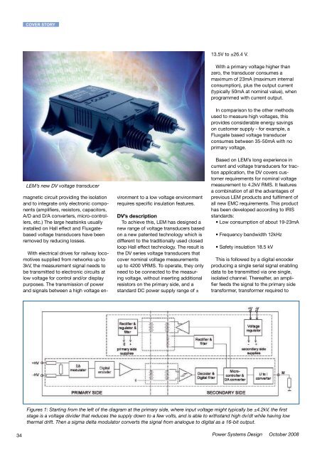
Figures 1: Starting from the left of the diagram at the primary side, where input voltage might typically be ±4.2kV, the first<br />
stage is a voltage divider that reduces the supply down to a few volts, and is able to withstand high dv/dt while having low<br />
thermal drift. Then a sigma delta modulator converts the signal from analogue to digital as a 16-bit output.<br />
<strong>Power</strong> <strong>Systems</strong> <strong>Design</strong> October 2008<br />
provide the desired galvanic isolation.<br />
Due to the high voltage environment, a<br />
double core transformer is considered,<br />
limited in size thanks to the considered<br />
high digital working frequency. Windings<br />
are wound into a PCB, similar in layout<br />
to a planar transformer, which affords<br />
product repeatability and assures component<br />
behaviour.<br />
The product is primarily designed for<br />
onboard traction and stationary traction<br />
substation applications. Within a<br />
substation the insulation test voltage is<br />
above 18kV for one minute for a working<br />
voltage of 4.2kV, while onboard, the<br />
insulation test voltage is max 13kV.<br />
The transformer therefore needs to<br />
withstand such a high test voltage,<br />
while at the same time the lifetime of the<br />
insulation can be guarantee by a partial<br />
discharge test, where a voltage is applied<br />
between the primary and secondary<br />
to determine if there is a discharge,<br />
which should measure less than 10 Pico<br />
coulombs.<br />
On the secondary side the bit-stream<br />
is decoded and filtered by a digital filter.<br />
Because the primary signal square wave<br />
is distorted by the transformer, there is<br />
a Schmitt trigger on the secondary side<br />
of the transformer to restore it to square<br />
wave. This is then fed into a decoder<br />
and digital filter, the function of which<br />
is to decode the data bit stream into a<br />
standard digital value that can be used<br />
in digital to analogue conversion within<br />
the microcontroller. The recovered<br />
output signal is completely insulated<br />
against the primary (high voltage), and<br />
is an exact representation of the primary<br />
voltage.<br />
The transducer can be easily adapted<br />
for different ranges by modifying the<br />
gain programmed by the microcontroller.<br />
This does not require changes in the design<br />
of the transformer or in the design<br />
of the assembly of the circuit boards in<br />
the housing. The microcontroller cancels<br />
offsets and adjusts the gain by software,<br />
and then converts the signal from digital<br />
to analogue output. The micro-controller<br />
transfers data from the digital filter to a<br />
12-bit D/A converter with a transfer time<br />
of around 6 μs. The analogue output<br />
voltage is then filtered and converted<br />
into a current (75mA full scale) using<br />
www.powersystemsdesign.com<br />
a current generator protected against<br />
short-circuits.<br />
The microcontroller also regulates a<br />
DC/DC converter that creates internal<br />
secondary regulated supply voltages<br />
supplied by customer DC supply which<br />
will typically be ±24V or ±15V, while<br />
also supplying ±5V and ±3.3V to the<br />
primary side sigma delta converter and<br />
digital encoder. The additional circuitry<br />
is shown as a group at the top of the<br />
circuit schematic, with the frequency<br />
of the DC to DC converter given by the<br />
microcontroller.<br />
The last block to the right of the<br />
microcontroller is a voltage to current<br />
converter for customers who prefer current<br />
output, typically 50mA, in order to<br />
comply with electromagnetic compatibility<br />
(EMC) regulations. The lower impedance<br />
current output is less prone to<br />
interference from external electromagnetic<br />
fields. A voltage output version<br />
to 10V is also available, for example,<br />
where the transducer is to be used with<br />
shielded cable or with short connections<br />
to customer electronics.<br />
Main characteristics<br />
Providing excellent overall accuracy<br />
with ±0.3% of VPN at ambient temperature<br />
and over its operating temperature<br />
range from -40°C to 85°C, the DV shows<br />
a low temperature drift resulting in an<br />
overall accuracy of only ±1 % of VPN.<br />
Initial offset at 25°C is 50μA max with a<br />
maximum possible drift of ±100μA over<br />
the operating temperature range. Sensitivity<br />
error at 25°C is ±0.2%. The microcontroller,<br />
used among other things for<br />
D/A conversion, is also useful for offset<br />
and gain adjustment during production,<br />
enabling these parameters. Linearity is<br />
only ±0.1%.<br />
The DV transducer’s typical response<br />
time (defined at 90% of VPN) against a<br />
voltage step at VPN has a delay of 48μs<br />
(Max 60µs). Other closed Loop based<br />
on Hall effect voltage transducers have<br />
a response delay of several hundred<br />
microseconds. As a result of the fast<br />
response time, a large bandwidth has<br />
been verified at 12kHz at -3 db (Fig. 3).<br />
Mechanical and standards<br />
The DV’s modular approach allows<br />
easy adaptation with various connec-<br />
COVER STORY<br />
tions available for the primary side, e.g.<br />
terminals or isolated cable, and any kind<br />
of connection for the secondary side like<br />
connectors, shielded cables, terminals<br />
(threaded studs, M4, M5, UNC etc.) according<br />
to customer specifications.<br />
The DV models have been designed<br />
and tested according to latest recognised<br />
worldwide standards for traction<br />
applications. The EN 50155 standard<br />
“Electronic Equipment used on Rolling<br />
stock” in railway applications is the<br />
standard of reference for electrical, environmental<br />
and mechanical parameters.<br />
It guarantees the overall performances<br />
of products in railway environments.<br />
LEM’s main production centres for<br />
traction transducers are IRIS certified -<br />
essential for companies supplying the<br />
railway market. DV transducers are CE<br />
marked as a guarantee of compliance<br />
to the European EMC directive 89/336/<br />
EEC and low voltage directive. They<br />
also comply with the derived local EMC<br />
regulations and with the EN 50121-3-2<br />
standard (railway EMC standard) in its<br />
latest update, with EMC constraints<br />
higher than that of the typical industrial<br />
application standards.<br />
The EN 50124-1 “Basic requirements<br />
- clearances and creepage distances for<br />
all electrical and electronic equipment”<br />
standard has been used as a reference<br />
to design the creepage and clearance<br />
distances for the DV transducers versus<br />
the required insulation levels (rated<br />
insulation voltage) and the conditions of<br />
use. Clearance is the shortest distance<br />
in air between two conductive parts and<br />
creepage is the shortest distance along<br />
the surface of the insulating material<br />
between two conductive parts. Pollution<br />
degree is application specific and is a<br />
way to classify the micro-environmental<br />
conditions having an effect on the insulation.<br />
Overvoltage category is also application<br />
specific and characterises the<br />
exposure of the equipment to overvoltage.<br />
Partial discharge (PD) is the dissipation<br />
of energy caused by the buildup<br />
of localised electric field intensity.<br />
Electric discharges partially bridge the<br />
insulation. Failure is by gradual erosion<br />
or ‘insulation, leading to puncture or<br />
surface flashover. The partial discharge<br />
35