Powering Freight & Transportation - Power Systems Design
Powering Freight & Transportation - Power Systems Design
Powering Freight & Transportation - Power Systems Design

Create successful ePaper yourself
Turn your PDF publications into a flip-book with our unique Google optimized e-Paper software.
58<br />
<strong><strong>Power</strong>ing</strong> <strong><strong>Power</strong>ing</strong> <strong>Freight</strong> <strong>Freight</strong> & <strong>Transportation</strong><br />
& <strong>Transportation</strong><br />
One Step Closer to<br />
the Birds<br />
Glider uses Vicor battery-controlled electrical<br />
propulsion to take to the air<br />
Gliding is one of the most exhilarating sports in the world. It offers a direct experience of air, wind and<br />
weather in a seemingly limitless space, and comes closest to man’s vision of the freedom of a bird’s<br />
flight. Crucial to this type of flying is the need to gain height in order to reach a thermal. Traditionally, a<br />
winch or a tow plane is used to pull the glider to sufficient altitude so that the fun of gliding in search of<br />
a thermal can begin. The requirement to return to the home airfield without additional support limited the<br />
use of gliders, and made careful flight planning a necessity.<br />
By Marco Panizza, European Applications Engineer, Vicor Europe, Germany<br />
Auxiliary propulsion systems<br />
brought an increase in range and<br />
flexibility, and made it possible<br />
to start gliders without additional towing<br />
tools. A conventional solution was<br />
using combustion motors. However, the<br />
performance of a combustion motor de-<br />
creases with its operating altitude. Combustion-powered<br />
propulsion systems<br />
must be oversized in order to deliver the<br />
desired power at all operating altitudes,<br />
and impose an important weight and<br />
noise burden on the glider. Additionally<br />
combustion engines generate substan-<br />
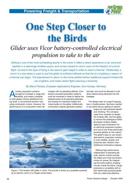
Figure 1: The Antares 20E glider in climb. The aircraft is driven by a propeller powered<br />
by an electric motor on a hinged carrier beam.<br />
tial heat, and must be allowed to cool<br />
down before being retracted into the<br />
fuselage.<br />
The design team at Lange Flugzeugbau<br />
in Zweibruecken, Germany wanted<br />
to set pilots free by adding an electric<br />
engine for self-powered takeoff<br />
and climbing. The company<br />
used Vicor modules to design<br />
the Antares 20E, the first glider<br />
to receive the prestigious EASA<br />
(European Aviation Safety<br />
Agency) type certification for<br />
an electrical propulsion system,<br />
and one of only three electrically<br />
powered gliders on the market.<br />
The glider’s easy to use retractable<br />
electric propulsion solution<br />
is more reliable, quieter, and<br />
produces less vibration than<br />
traditional combustion engines.<br />
Offering high performance<br />
independent of operating altitude,<br />
electric motors provide<br />
the safest and most convenient<br />
choice for power. By integrating<br />
the entire battery charging<br />
circuitry inside the plane, Lange<br />
produced a completely self-reliant<br />
electrically-powered glider<br />
that can make long-distance<br />
<strong>Power</strong> <strong>Systems</strong> <strong>Design</strong> October 2008<br />
flights, and be recharged at any airfield.<br />
The need for good aerodynamic<br />
performance, however, imposes strict<br />
limits on the weight of the entire system,<br />
particularly that of batteries and charging<br />
circuitry.<br />
<strong>Design</strong> challenges<br />
One of the challenges in the design<br />
of the glider was the integration of the<br />
battery charging subsystem. The entire<br />
system had to be self-reliant in order to<br />
enable long-distance multi-lap flights<br />
without the need for an external charging<br />
unit at the airfield. The propulsion<br />
motor has a nominal power of 42kW<br />
and operates on a voltage of 288V. The<br />
battery system has to provide enough<br />
power for five minutes of operation or<br />
about 3000m of climbing altitude, which<br />
translates into an overall battery capacity<br />
of 11kWh. Charging has to use a<br />
normal single-phase mains connection,<br />
and a full charging cycle needs to be<br />
completed overnight.<br />
The glider uses Li-Ion battery cells<br />
which require tightly controlled operating<br />
conditions to deliver a consistent,<br />
reliable power output. In order to offer<br />
maximum capacity, the cells must be<br />
operated between 20 and 40°C, so<br />
temperature sensing and cell heating<br />
had to be implemented. Additionally all<br />
cells must be kept on the same charging<br />
state, requiring cell voltage monitoring<br />
circuitry to ensure that all cells<br />
have identical cell voltages. Before any<br />
charge cycle, all cells are discharged to<br />
have the same cell voltage with a tolerance<br />
of only ±20mV ensuring that all<br />
cells will be charged evenly. In practice,<br />
charging is several activities that must<br />
be performed in sequence:<br />
• Cell voltage monitoring and selective<br />
discharging until all cells have the same<br />
voltage within the specified tolerance<br />
• Cell heating until the desired operating<br />
temperature is reached<br />
• Battery array charging until the total<br />
voltage reaches 288V<br />
In addition, the charging electronics<br />
have to fit into the overall system of the<br />
glider. This means that the circuitry has<br />
to meet rigorous, weight, heat management<br />
and size specifications.<br />
www.powersystemsdesign.com<br />
<strong><strong>Power</strong>ing</strong> <strong>Freight</strong> & <strong>Transportation</strong><br />
Choosing a charging<br />
module vendor<br />
Since total glider weight has a direct<br />
impact on its flying performance, all<br />
components in the aircraft had to be optimized<br />
for lowest possible weight. Commercially<br />
available chargers that met the<br />
specifications would weigh about 10kg<br />
including mains front-end and cabling –<br />
much too heavy for integration in a glider<br />
with a maximum total takeoff weight of<br />
660kg. As Lange’s design engineers<br />
could not find ready-made charging<br />
units that met the weight requirements,<br />
a new charging subsystem had to be<br />
developed.<br />
The charging subsystem essentially<br />
consists of a mains front-end and a high<br />
voltage, high-power DC-DC converter<br />
with programmable output voltage.<br />
Due to space and weight limitations,<br />
the circuits had to offer high efficiency,<br />
as a major factor in the overall weight<br />
Figure 2: Charging system block diagram. The front-end and the power section<br />
are housed in two separate cabinets and are mounted in the glider’s fuselage.<br />
The front-end consists of the EN1C21 Vicor modules while the power section<br />
comprises Vicor Module V300B48T250BL Vicor DC-DC converters. The power<br />
section is connected to the battery array, which is installed inside the wings.<br />
59