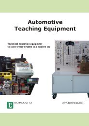
THEPRA-LAB: PCB Lab System
THEPRA-LAB: PCB Lab System
THEPRA-LAB: PCB Lab System

Create successful ePaper yourself
Turn your PDF publications into a flip-book with our unique Google optimized e-Paper software.
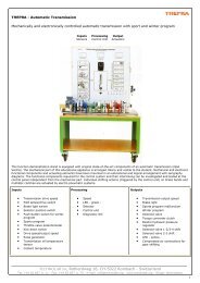
<strong>THEPRA</strong>-<strong>LAB</strong>: <strong>PCB</strong> lab system<br />
Car actuator technology - diagnosis basics<br />
On the output side of an electronic control<br />
or regulation system, the assessment results<br />
of the microprocessor can be measured<br />
as actuator control voltages.<br />
In state-of-the-art vehicle systems, onboard-diagnosis<br />
is a standard. Workshop<br />
practice, however, shows that output interferences<br />
recognised by the control unit<br />
are only formulated in very vague detail in<br />
the error storage. The reason for this is the<br />
fact that a control unit cannot actually<br />
recognise whether the driving stage in the<br />
control unit, the connection lines to the<br />
actuator or the actuator as such are defective.<br />
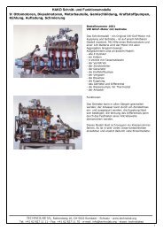
The present lab system with its diverse<br />
practice-related actuators of intact and<br />
defective systems provides real measured<br />
values. Type, structure and alignment of<br />
the components facilitate transfer competence<br />
from pure theory to the locally installed<br />
vehicle components. The student documents<br />
contain not only instructions but<br />
also physical basic information on the<br />
actuator and control current branch.<br />
Special importance is placed on handling<br />
the oscilloscope and assessment of the<br />
diagnosis images .<br />
Educational targets<br />
��In vehicle-related circuit examples, they<br />
will learn about performance and indicativeness<br />
of actuator diagnosis.<br />
��In vehicle-related switching examples,<br />
they will develop the actuator-typical<br />
voltage values of the intact and defective<br />
control current branches.<br />
��They use multimeters and oscilloscopes<br />
for actual value recording. They interpret<br />
the oscilloscope charts.<br />
��They will learn how to "read" oscilloscope<br />
charts by documenting the indication<br />
of the oscilloscope and the set time and<br />
voltage parameters in prepared or free<br />
axes of coordinates and interpreting<br />
them.<br />
E 24<br />
��They will practice how to proceed in<br />
measurement if they want to verify<br />
whether the control unit end stage, actuator<br />
lines or the actuator itself are defective.<br />
The task and exercises refer to the<br />
few measuring points that are accessible<br />
in a state-of-the-art vehicle filled<br />
with electrical components.<br />
��They improve their skills at recognising<br />
incorrect values and error causes in self<br />
-generated and provided actual value<br />
logs .<br />
Electrics and Electronics<br />
<strong>PCB</strong> 4<br />
Car actuator technology - diagnosis<br />
basics<br />
Order No. 12 020 013<br />
For best equipment, we also recommend:<br />
12 050 011 DC lab mains adaptor<br />
12 020 020 Wire harness 2 mm plug<br />
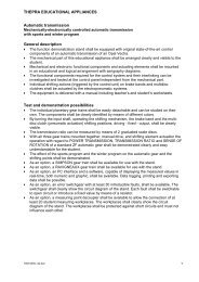
12 020 021 Wire harness wit insulatedalligator<br />
clips<br />
16 062 012 Universal multimeter<br />
16 162 020 Oscilloscope 25 MHz<br />
16 162 015 Oscilloscope 20 MHz with<br />
True RMS Multimeter<br />
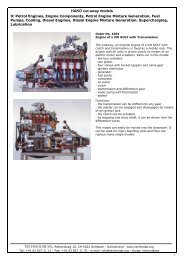
Fig.: 12 020 021 Wire harness<br />
with insulated alligator clips<br />
Modifications reserved!<br />
_________________________________________________________________________________________________________<br />
TECHNO<strong>LAB</strong> SA, Rotherdweg 16, CH-5022 Rombach/Switzerland - Tel +41 62 827 11 11 - info@technolab.org - www.technolab.org<br />
8