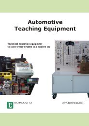
THEPRA-LAB: PCB Lab System
THEPRA-LAB: PCB Lab System
THEPRA-LAB: PCB Lab System

You also want an ePaper? Increase the reach of your titles
YUMPU automatically turns print PDFs into web optimized ePapers that Google loves.
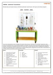
Electrics and Electronics<br />
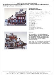
<strong>THEPRA</strong>-<strong>LAB</strong>: <strong>PCB</strong> <strong>Lab</strong> <strong>System</strong><br />
The new subject-comprehensive lab system consists of four individual <strong>PCB</strong>s and covers all subjects from the basic principles to actor<br />
technology. The system comprises all required components; it is compact, can be used at once, and permits free wiring. The focus of<br />
the pedagogically valuable course documents is on car diagnosis.<br />
Largest Possible Car Relation<br />
��Plus supply for each circuit set-up<br />
secured (5 A). Plus supply can be<br />
switched on and off according to<br />
ignition switch in the car.<br />
��Plus- and minus-side "corrosion<br />
resistance" can be switched on to<br />
simulate noticeable voltage drops<br />
(corroded contacts).<br />
��Indirect power measurement (voltage<br />
drop as current measurement method)<br />
is practised. Avoids danger of<br />
destruction of measuring device.<br />
��Tasks with reference to real order<br />
processing (OBD-reference and<br />
diagnosis levels).<br />
��Voltage distribution in the circuits as<br />
diagnosis criterion, as practised in onboard<br />
and off-board diagnosis.<br />
��Multimeter and oscilloscope as<br />
measuring devices<br />
��Suitable for car, industrial, agricultural<br />
and construction machinery training<br />
Lesson Design Individual / Variable<br />
��Clear setting of tasks with prepared<br />
measuring protocols<br />
��Task processing and assessment<br />
frontal, in groups or separately<br />
(component diversity)<br />
��Repetition and improvement of<br />
specialist competence<br />
��Detailed and comprehensive calculations<br />
and assessments<br />
��Transfer of general connections into<br />
concrete diagnosis situations<br />
��Pre-determined error logs for assessment<br />
and diagnosis<br />
��Detailed sample solutions and special<br />
notes in the teacher leaflet<br />
Thermal Protection<br />
��High-performance components and<br />
direct current switches.<br />
��Transistors and thyristors additionally<br />
secured against excessive voltages and<br />
overcurrent at wrong connection.<br />
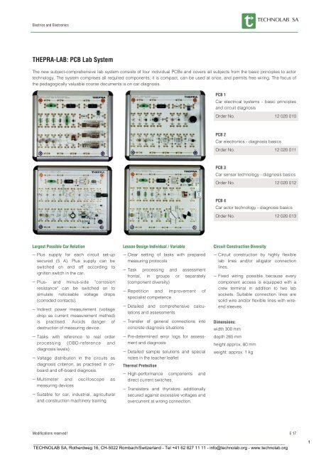
<strong>PCB</strong> 1<br />
Car electrical systems - basic principles<br />
and circuit diagnosis<br />
Order No. 12 020 010<br />
<strong>PCB</strong> 2<br />
Car electronics - diagnosis basics<br />
Order No. 12 020 011<br />
<strong>PCB</strong> 3<br />
Car sensor technology - diagnosis basics<br />
Order No. 12 020 012<br />
<strong>PCB</strong> 4<br />
Car actor technology - diagnosis basics<br />
Order No. 12 020 013<br />
Circuit Construction Diversity<br />
��Circuit construction by highly flexible<br />
lab lines and/or alligator connection<br />
lines.<br />
��Fixed wiring possible because every<br />
component access is equipped with a<br />
crew terminal in addition to two lab<br />
sockets. Suitable connection lines are<br />
solid wire and/or flexible lines with wireend<br />
sleeves.<br />
Dimensions:<br />
width 300 mm<br />
depth 265 mm<br />
height approx. 80 mm<br />
weight: approx. 1 kg<br />
Modifications reserved! E 17<br />
_________________________________________________________________________________________________________<br />
TECHNO<strong>LAB</strong> SA, Rotherdweg 16, CH-5022 Rombach/Switzerland - Tel +41 62 827 11 11 - info@technolab.org - www.technolab.org<br />
1
<strong>THEPRA</strong>-<strong>LAB</strong>: <strong>PCB</strong> lab system<br />
Car electrical systems - basic principles and circuit diagnosis<br />
Diagnosis of electrical systems is essential<br />
at the car service workshop. The basis of<br />
diagnosis is the competence of recognising<br />
the electrical basic principles applied<br />
in the diverse, networked vehicle systems,<br />
how they interact in a partial system and<br />
how to verify this in measurements.<br />
In the end these initially seemingly chaotic<br />
partial and overall systems can be reduced<br />
to complete circuits where the basic<br />
principles apply.<br />
It can be assumed that the trainees targeted<br />
here are not dealing with electrical<br />
engineering for the first time. Still, the first<br />
tasks may commence with basic circuits<br />
already known to confirm what was taught<br />
before.<br />
When using vehicle lamps in the basic<br />
circuits and collecting experience with non<br />
-linear behaviour, the learners make their<br />
first step into the professional world .<br />
Educational targets<br />
��Even in task 1, they will improve their<br />
measuring and calculation knowledge of<br />
the principles of electrical circuits with<br />
genuine vehicle lamps.<br />
��They will learn about the laws of the<br />
different circuit types and apply them in<br />
vehicle lamp circuits.<br />
��In the third section, they will recognise<br />
how the overall voltage is divided in an<br />
intact and a defective circuit.<br />
��They learn about indications for error<br />
points in the measuring log of a defective<br />
current branch.<br />
E 18<br />
��In a vehicle-related relay control, they<br />
learn about the interaction of the components.<br />
��In an intact and a defective relay control,<br />
they can see how voltage measurement<br />
alone is sufficient to diagnose this<br />
vehicle-typical circuit<br />
Electrics and Electronics<br />
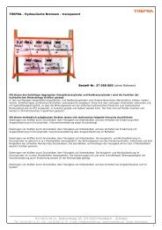
<strong>PCB</strong> 1<br />
Car electrical systems - basic principles<br />
and circuit diagnosis .<br />
Order No. 12 020 010<br />
For best equipment, we also recommend:<br />
12 050 011 DC lab mains adaptor<br />
12 020 020 Wire harness 2 mm plug<br />
12 020 021 Wire harness with insulated<br />
alligator clips<br />
16 062 012 Universal multimeter<br />
16 162 020 Oscilloscope 25 MHz<br />
16 162 015 Oscilloscope 20 MHz with<br />
True RMS Multimeter<br />
The unique course<br />
comprises comprehensivedocumentation<br />
and extensive<br />
worksheets for teachers<br />
and students. The<br />
solutions book contains additional further<br />
explanations and solution charts.<br />
Modifications reserved!<br />
_________________________________________________________________________________________________________<br />
TECHNO<strong>LAB</strong> SA, Rotherdweg 16, CH-5022 Rombach/Switzerland - Tel +41 62 827 11 11 - info@technolab.org - www.technolab.org<br />
2
Electrics and Electronics<br />
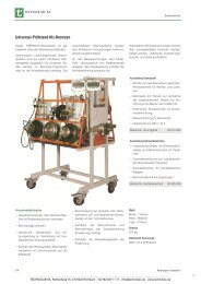
<strong>THEPRA</strong>-<strong>LAB</strong>: <strong>PCB</strong> <strong>Lab</strong> system<br />
Car electrical systems - basic principles and circuit diagnosis<br />
1. Positive connection (terminal 30)<br />
2. Resistor, 100 Ω, 3 W<br />
3. Resistor, 220 Ω, 3 W<br />
4. Resistor, 330 Ω, 3 W<br />
5. Control switch, I - O<br />
6. Time-lag fuse, 5 A<br />
7. Rectifier diode<br />
8. E 10 holder, e.g. 12 V / 1.2 W<br />
9. E 10 holder, e.g. 12 V / 2.4 W<br />
10. E 10 holder, e.g. 12 V / 6 W<br />
11. Negative connection (terminal 31)<br />
12. Space for battery ground strap<br />
13. Terminals for relay, component 14<br />
14. 12-V relay with change-over contact<br />
15. Negative power rail, corresponds to<br />
car body<br />
16. Negative socket for the connection of<br />
further lab panels<br />
17. Automotive bulb, e.g. 12 V / 21 W<br />
(indicator bulb, brake light)<br />
18. Automotive bulb, e.g. 12 V / 10 W<br />
(licence-plate lamp)<br />
19. Automotive bulb, e.g. 12 V / 5 W (side<br />
light)<br />
20. Prezion shunt, 1 Ω, max. 1 A<br />
21. Prezions shunt, 0,1 Ω<br />
22. Positive socket for the connection of<br />
further lab panels<br />
23. Highly-resilient switch<br />
24. Positive power rail, corresponds to<br />
continuous connection to the positive<br />
terminal (terminal 30)<br />
25. Highly-resilient switch (e.g. ignition<br />
switch)<br />
26. Time-lag fuse, 5 A, e.g. main fuse<br />
Modifications reserved! E 19<br />
_________________________________________________________________________________________________________<br />
TECHNO<strong>LAB</strong> SA, Rotherdweg 16, CH-5022 Rombach/Switzerland - Tel +41 62 827 11 11 - info@technolab.org - www.technolab.org<br />
3
<strong>THEPRA</strong>-<strong>LAB</strong>: <strong>PCB</strong> lab system<br />
Car electronics - diagnosis basics<br />
In vehicle systems, very different electronics<br />
components are integrated in circuits.<br />
A prerequisite for secure diagnosis is<br />
knowledge of the component features and<br />
competence to verify function by measurements.<br />
Information, measuring circuits and assessments<br />
focus on vehicle-related situations<br />
out of the great variety of application<br />
options.<br />
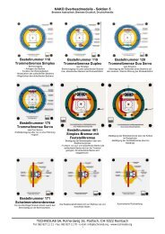
<strong>PCB</strong> 2<br />
Car electronics - diagnosis basics<br />
Order No. 12 020 011<br />
Educational targets<br />
��In vehicle-related circuits, you will learn<br />
about the characteristics of rectifier<br />
diodes and Z-diodes and their measuring<br />
technology presentation and log the<br />
results.<br />
��They will independently examine the<br />
characteristics and their measuringtechnical<br />
presentation of optoelectronics<br />
components relating to vehicles<br />
and log the requests.<br />
��After processing the section on transistors,<br />
you will know the different characteristics<br />
of bipolar and unipolar transistors.<br />
For best equipment, we also recommend:<br />
12 050 011 DC lab mains adaptor<br />
12 020 020 Wire harness 2 mm plug<br />
12 020 021 Wire harness with insulated<br />
alligator clips<br />
16 062 012 Universal multimeter<br />
16 162 020 Oscilloscope 25 MHz<br />
16 162 015 Oscilloscope 20 MHz with<br />
True RMS multimeter<br />
E 20<br />
��After working through the section on<br />
transistors, you will be able to explain<br />
different options for application of<br />
"transistors as switches" and "transistors<br />
as amplifiers" in general and relating to<br />
measuring technology.<br />
��After working through the section on<br />
transistors, you will be able to prove<br />
heat development in half- and wholly<br />
interconnected transistors mathematically<br />
using the measured values. They<br />
will understand why defective driving<br />
stages in electronic vehicle systems will<br />
not only destroy themselves but also<br />
connected components.<br />
Electrics and Electronics<br />
��They will learn about the characteristics<br />
of a thyristor and be able to prove its<br />
behaviour by measuring technology.<br />
��When working through the final chapter<br />
on capacitators, you will learn about the<br />
capacitator characteristics and measuring-technical<br />
presentation and how to<br />
explain them.<br />
Modifications reserved!<br />
_________________________________________________________________________________________________________<br />
TECHNO<strong>LAB</strong> SA, Rotherdweg 16, CH-5022 Rombach/Switzerland - Tel +41 62 827 11 11 - info@technolab.org - www.technolab.org<br />
4
Electrics and Electronics<br />
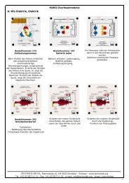
<strong>THEPRA</strong>-<strong>LAB</strong>: <strong>PCB</strong> lab system<br />
Car electronics - diagnosis basics<br />
1. Positive connection (terminal 30)<br />
2. Resistor, 1 kΩ / 0.5 W<br />
3. Resistor, 100 kΩ / 0.5 W<br />
4. Rectifier diode<br />
5. Z diode<br />
6. Rotary knob for potentiometer<br />
7. Potentiometer (R5)<br />
8. Light emitting diode (LED)<br />
9. Photoresistor (LDR)<br />
10. E 10 holder, z. B. 12 V / 1.2 W<br />
11. Negative connection (terminal 31)<br />
12. Space for battery ground strap<br />
13. Photocell/photo diode<br />
14. Protective base resistor (NPN)<br />
15. Protective resistor for basic measuring<br />
instruments X1<br />
16. Overbuilt cooling element of the NPN<br />
transistor<br />
17. Electronic collector protection<br />
18. Gate protection resistor (MOSFET)<br />
19. Protective resistor for gate measuring<br />
instruments X3<br />
20. Overbuilt cooling element of the MOS-<br />
FET<br />
21. Electronic drain protection<br />
22. Negative power rail (car body)<br />
23. Negative socket for the connection of<br />
further lab panels<br />
24. Protective resistor for gate measuring<br />
instruments X5<br />
25. Thyristor<br />
26. Gate protection resistor (thyristor)<br />
27. Key as make-contact<br />
28. Capacitor, 25 V / 10,000 μF<br />
29. Change-over switch I-O-I (1-0-2)<br />
30. Prezision shunt, 1 Ω / max. 1 A<br />
31. Positive socket for the connection of<br />
further lab panels<br />
32. Prezision shunt, 0,1 Ω<br />
33. Positive power rail, corresponds to<br />
continuous connection to the positive<br />
terminal (terminal 30)<br />
34. Highly-resilient switch<br />
35. Time-lag fuse, 5 A (main fuse)<br />
Modifications reserved! E 21<br />
_________________________________________________________________________________________________________<br />
TECHNO<strong>LAB</strong> SA, Rotherdweg 16, CH-5022 Rombach/Switzerland - Tel +41 62 827 11 11 - info@technolab.org - www.technolab.org<br />
5
<strong>THEPRA</strong>-<strong>LAB</strong>: <strong>PCB</strong> lab system<br />
Car sensor technology - diagnosis basics<br />
This subject summary takes into consideration<br />
the fact that all electronic vehicles<br />
systems record the actual value of a partial<br />
system under consideration with sensors.<br />
Sensors convert non-electrical physical<br />
values like positions of actuators, temperatures,<br />
pressure, brightness, etc. to electrical<br />
voltage that is decrypted by a control<br />
device.<br />
A control unit digitises the course over<br />
time, height and frequency of the sensor<br />
voltages to further process these actual<br />
values in the micro controller.<br />
In state-of-the-art vehicle systems, onboard-diagnosis<br />
is a standard. Workshop<br />
practice shows, however, that any input<br />
interferences recognised by the control<br />
unit are only formulated in very vague<br />
detail in the error storage. The reason for<br />
this is the fact that a control unit cannot<br />
actually recognise whether the sensor, its<br />
connection lines to the control unit or digitalisation<br />
in the control unit are defective.<br />
This is where the service workshop comes<br />
in, where the sensor-side is diagnosed by<br />
measuring technology.<br />
The present lab system provides real measured<br />
values for the intact and defective<br />
system by the diversity of practice-related<br />
sensors. Type, structure and alignment of<br />
the components facilitate transfer compe-<br />
Educational targets<br />
��They get to know the sensor-typical<br />
voltage values of the intact and defective<br />
sensor current branches in vehiclerelated<br />
circuit examples.<br />
��They use multimeters and oscilloscopes<br />
for actual value recording. They interpret<br />
the oscilloscope charts.<br />
��In examples and additional figure<br />
examples, they will recognise the mathematical<br />
interrelations between the<br />
non-electrical actual value of the physical<br />
measured value and the voltage<br />
value the control unit receives from the<br />
sensor.<br />
E 22<br />
tence from pure theory to the locally installed<br />
vehicle components. The student documents<br />
contain not only instructions but<br />
also physical basic information on the<br />
sensor and measuring current branch.<br />
��They learn how to use charts that present<br />
a target value logarithmically.<br />
��They practice how to proceed measuring-technically<br />
to find out whether the<br />
sensor or the line is defective. The task<br />
and exercises refer to the few measuring<br />
points that are accessible in a state<br />
-of-the-art vehicle filled with electrical<br />
components.<br />
��They improve their skills at recognising<br />
incorrect values and error causes in self<br />
-generated and provided actual value<br />
logs.<br />
Electrics and Electronics<br />
<strong>PCB</strong> 3<br />
Car sensor technology - diagnosis basics<br />
Order No. 12 020 012<br />
For best equipment, we also recommend:<br />
12 050 011 DC lab mains adaptor<br />
12 020 020 Wire harness 2 mm plug<br />
12 020 021 Wire harness wit insulatedalligator<br />
clips<br />
16 062 012 Universal multimeter<br />
16 162 020 Oscilloscope 25 MHz<br />
16 162 015 Oscilloscope 20 MHz with<br />
True RMS multimeter<br />
Plastic storage case, light grey with foam inserts - order<br />
no . 12 020 022<br />
Modifications reserved!<br />
_________________________________________________________________________________________________________<br />
TECHNO<strong>LAB</strong> SA, Rotherdweg 16, CH-5022 Rombach/Switzerland - Tel +41 62 827 11 11 - info@technolab.org - www.technolab.org<br />
6
Electrics and Electronics<br />
<strong>THEPRA</strong>-<strong>LAB</strong>: <strong>PCB</strong> lab system<br />
Car sensor technology - diagnosis basics<br />
1. Positive connection (terminal 30)<br />
2. Control switch, E-A<br />
3. Resistor, 1 kΩ<br />
4. Resistor, 1 kΩ<br />
5. Resistor, 100 kΩ<br />
6. Pressure sensor / force sensor<br />
7. Piezo sensor as knock sensor<br />
8. Photoresistor<br />
9. E 10 holder, z. B. 12 V / 6 W<br />
10. Photo diode/Fotoelement<br />
11. Negative connection (terminal 31)<br />
12. Space for battery ground strap<br />
13. NTC resistor<br />
14. PTC resistor<br />
15. Hot film sensor<br />
16. Inductive sensor<br />
17. Protective wiring and signal<br />
processing<br />
18. Negative power rail, corresponds to<br />
car body<br />
19. Negative socket for the connection of<br />
further lab panels<br />
20. Drive electronics for 22<br />
21. Hall sensor<br />
22. Sensor wheel for 16 and 21<br />
23. Twin / tandem potentiometer<br />
24. Resistor, 470 Ω<br />
25. Positive socket for the connection of<br />
further lab panels<br />
26. Precision shunt, 1 Ω<br />
27. Direct voltage source, 5 V, stabilised<br />
(control unit)<br />
28. Positive power rail<br />
29. Highly-resilient direct-current switch,<br />
e.g. ignition switch<br />
30. Fuse, 1 A<br />
Modifications reserved! E 23<br />
_________________________________________________________________________________________________________<br />
TECHNO<strong>LAB</strong> SA, Rotherdweg 16, CH-5022 Rombach/Switzerland - Tel +41 62 827 11 11 - info@technolab.org - www.technolab.org<br />
7
<strong>THEPRA</strong>-<strong>LAB</strong>: <strong>PCB</strong> lab system<br />
Car actuator technology - diagnosis basics<br />
On the output side of an electronic control<br />
or regulation system, the assessment results<br />
of the microprocessor can be measured<br />
as actuator control voltages.<br />
In state-of-the-art vehicle systems, onboard-diagnosis<br />
is a standard. Workshop<br />
practice, however, shows that output interferences<br />
recognised by the control unit<br />
are only formulated in very vague detail in<br />
the error storage. The reason for this is the<br />
fact that a control unit cannot actually<br />
recognise whether the driving stage in the<br />
control unit, the connection lines to the<br />
actuator or the actuator as such are defective.<br />
The present lab system with its diverse<br />
practice-related actuators of intact and<br />
defective systems provides real measured<br />
values. Type, structure and alignment of<br />
the components facilitate transfer competence<br />
from pure theory to the locally installed<br />
vehicle components. The student documents<br />
contain not only instructions but<br />
also physical basic information on the<br />
actuator and control current branch.<br />
Special importance is placed on handling<br />
the oscilloscope and assessment of the<br />
diagnosis images .<br />
Educational targets<br />
��In vehicle-related circuit examples, they<br />
will learn about performance and indicativeness<br />
of actuator diagnosis.<br />
��In vehicle-related switching examples,<br />
they will develop the actuator-typical<br />
voltage values of the intact and defective<br />
control current branches.<br />
��They use multimeters and oscilloscopes<br />
for actual value recording. They interpret<br />
the oscilloscope charts.<br />
��They will learn how to "read" oscilloscope<br />
charts by documenting the indication<br />
of the oscilloscope and the set time and<br />
voltage parameters in prepared or free<br />
axes of coordinates and interpreting<br />
them.<br />
E 24<br />
��They will practice how to proceed in<br />
measurement if they want to verify<br />
whether the control unit end stage, actuator<br />
lines or the actuator itself are defective.<br />
The task and exercises refer to the<br />
few measuring points that are accessible<br />
in a state-of-the-art vehicle filled<br />
with electrical components.<br />
��They improve their skills at recognising<br />
incorrect values and error causes in self<br />
-generated and provided actual value<br />
logs .<br />
Electrics and Electronics<br />
<strong>PCB</strong> 4<br />
Car actuator technology - diagnosis<br />
basics<br />
Order No. 12 020 013<br />
For best equipment, we also recommend:<br />
12 050 011 DC lab mains adaptor<br />
12 020 020 Wire harness 2 mm plug<br />
12 020 021 Wire harness wit insulatedalligator<br />
clips<br />
16 062 012 Universal multimeter<br />
16 162 020 Oscilloscope 25 MHz<br />
16 162 015 Oscilloscope 20 MHz with<br />
True RMS Multimeter<br />
Fig.: 12 020 021 Wire harness<br />
with insulated alligator clips<br />
Modifications reserved!<br />
_________________________________________________________________________________________________________<br />
TECHNO<strong>LAB</strong> SA, Rotherdweg 16, CH-5022 Rombach/Switzerland - Tel +41 62 827 11 11 - info@technolab.org - www.technolab.org<br />
8
Electrics and Electronics<br />
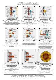
<strong>THEPRA</strong>-<strong>LAB</strong>: <strong>PCB</strong> lab system<br />
Car actuator technology - diagnosis basics<br />
1. Positive connection (terminal 30)<br />
2. Precision shunt, 0,1 Ω<br />
3. Precision shunt, 1 Ω<br />
4. Resistor, 33 Ω<br />
5. Slide switch, E-A<br />
6. Light emitting diode with protective<br />
resistor<br />
7. Diode<br />
8. E 10 holder, z. B. 12 V / 6 W<br />
9. Gate protection resistor<br />
10. Gate protection resistor X1<br />
11. Negative connection (terminal 31)<br />
12. Protective wiring<br />
13. Overbuilt cooling element (MOSFET)<br />
14. Space for battery ground strap<br />
15. Protective base resistor (NPN)<br />
16. Protective resistor for basic measuing<br />
instruments X3<br />
17. Overbuilt cooling element (NPN)<br />
18. Electronic collector protection<br />
19. Protective wiring für 20<br />
20. Proportionalversteller/-ventil<br />
21. Protective wiring für 22<br />
22. Collector motor<br />
23. Negative power rail (car body)<br />
24. Negative socket for the connection of<br />
further lab panels<br />
25. Injector<br />
26. Relay as actuator<br />
27. Positive socket for the connection of<br />
further lab panels<br />
28. PWM generator (control unit)<br />
29. Direct voltage source, 5 V, stabilised<br />
(control unit)<br />
30. Positive power rail<br />
31. Highly-resilient direct-current switch,<br />
e.g. ignition switch<br />
32. Fuse, 1 A<br />
Modifications reserved! E 25<br />
_________________________________________________________________________________________________________<br />
TECHNO<strong>LAB</strong> SA, Rotherdweg 16, CH-5022 Rombach/Switzerland - Tel +41 62 827 11 11 - info@technolab.org - www.technolab.org<br />
9