Scroll Liquid Chillers Model CGWF and CCAF 20 to ... - Climas Trane
Scroll Liquid Chillers Model CGWF and CCAF 20 to ... - Climas Trane
Scroll Liquid Chillers Model CGWF and CCAF 20 to ... - Climas Trane

Create successful ePaper yourself
Turn your PDF publications into a flip-book with our unique Google optimized e-Paper software.
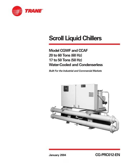
<strong>Scroll</strong> <strong>Liquid</strong> <strong>Chillers</strong><br />
<strong>Model</strong> <strong>CGWF</strong> <strong>and</strong> <strong>CCAF</strong><br />
<strong>20</strong> <strong>to</strong> 60 Tons (60 Hz)<br />
17 <strong>to</strong> 50 Tons (50 Hz)<br />
Water-Cooled <strong>and</strong> Condenserless<br />
Built For the Industrial <strong>and</strong> Commercial Markets<br />
January <strong>20</strong>04<br />
CG-PRC012-EN
More Than Just Another “Improved”<br />
Chiller<br />
— Advanced Design<br />
— Better Reliability<br />
— Superior Efficiency<br />
— New CH530 Controls<br />
— Better Availability<br />
— Easier To Install <strong>and</strong> Operate<br />
Condenser<br />
Leaving<br />
Water<br />
Piping<br />
Condenser<br />
Entering<br />
Water<br />
Piping<br />
Microprocessor<br />
Opera<strong>to</strong>r<br />
Interface<br />
Control<br />
Panel<br />
© <strong>20</strong>04 American St<strong>and</strong>ard Inc. All rights reserved.<br />
Introduction<br />
The <strong>Trane</strong> <strong>20</strong>-60 Ton <strong>Scroll</strong> <strong>Liquid</strong> Chiller<br />
Design<br />
The <strong>Trane</strong> scroll compressor is the most<br />
advanced scroll compressor in the<br />
industry.<br />
Reliability<br />
64 percent fewer compressor parts,<br />
compared <strong>to</strong> reciprocating compressors,<br />
mean long <strong>and</strong> reliable life.<br />
Efficiency<br />
<strong>CGWF</strong> scroll chillers meet <strong>and</strong> exceed<br />
ASHRAE St<strong>and</strong>ard 90.1 full <strong>and</strong> part load<br />
efficiencies. Part load efficiencies are<br />
simply unmatched by reciprocating<br />
chillers.<br />
Control<br />
CH530 controls enable scrolling access<br />
<strong>to</strong> inputs <strong>and</strong> operating information via<br />
the LCD <strong>to</strong>uch-screen display. Jobspecific<br />
communication options allow<br />
greater reporting flexibility. The CH530 is<br />
compatable with LonMark<br />
communications.<br />
Availability<br />
Fast ship cycles on both s<strong>to</strong>ck <strong>and</strong> built<strong>to</strong>-order<br />
specials.<br />
Installation<br />
Small unit size, fac<strong>to</strong>ry wiring, easy<br />
lifting provisions, <strong>and</strong> start-up control<br />
logic mean quick <strong>and</strong> easy setup.<br />
<strong>Chillers</strong> fit through st<strong>and</strong>ard singlewidth<br />
door.<br />
Operation<br />
Smart safety features <strong>and</strong> over 60<br />
diagnostic displays mean easy <strong>and</strong><br />
virtually trouble-free operation.<br />
Rugged<br />
<strong>Trane</strong> <strong>Scroll</strong><br />
Compressor<br />
Evapora<strong>to</strong>r<br />
Leaving<br />
Water Piping<br />
CG-PRC012-EN
CG-PRC012-EN<br />
Contents<br />
Introduction<br />
Features <strong>and</strong> Benefits<br />
World Class Efficiency <strong>and</strong> Reliability<br />
Options<br />
Controls<br />
Application Considerations<br />
<strong>Model</strong> Number<br />
General Data<br />
Selection Procedure<br />
Performance Data<br />
Full Load Performance<br />
Part Load Performance<br />
Adjustment Fac<strong>to</strong>rs<br />
Pressure Drops<br />
Electrical Data <strong>and</strong> Connections<br />
Typical Wiring Diagram<br />
Field Layout<br />
Dimensional Data<br />
Weights<br />
Mechanical Specifications<br />
3<br />
2<br />
4<br />
8<br />
12<br />
13<br />
14<br />
15<br />
16<br />
27<br />
32<br />
37<br />
38
4<br />
Features <strong>and</strong><br />
Benefits<br />
<strong>Trane</strong> Value Means Fast Availability,<br />
Easy Installation <strong>and</strong> Quality Service<br />
Packed S<strong>to</strong>ck For Fast Delivery<br />
When your project is a fast-track job,<br />
<strong>Trane</strong> can help. A wide range of chillers<br />
are s<strong>to</strong>cked <strong>and</strong> can be shipped soon<br />
after receipt of your order.<br />
Build To Order<br />
Need a special chiller fast? Think <strong>Trane</strong><br />
scroll chillers. New manufacturing<br />
technology <strong>and</strong> inven<strong>to</strong>ry control means<br />
the fastest delivery schedule in the<br />
industry. Wide array of st<strong>and</strong>ard options<br />
provides the right chiller for the job fast.<br />
Installation<br />
Only one power connection hook-up —<br />
for fast <strong>and</strong> inexpensive installation.<br />
Integrated Comfort system means<br />
only single pair connections are<br />
required for control interfaces <strong>and</strong><br />
therefore, lower <strong>to</strong>tal installation costs.<br />
Fac<strong>to</strong>ry refrigerant <strong>and</strong> oil charged<br />
units help speed installation.<br />
All units easily fit through a st<strong>and</strong>ard<br />
single width door.<br />
CH530 provides a wealth of<br />
information.<br />
Fac<strong>to</strong>ry testing of all <strong>Trane</strong> equipment<br />
ensures the system works, allowing<br />
smoother start-up & reducing follow-up<br />
costs.<br />
Easy Serviceability<br />
<strong>Trane</strong> <strong>20</strong> through 60 <strong>to</strong>n scroll chillers<br />
are designed with service personnel in<br />
mind. All major components are<br />
replaceable without complete unit<br />
disassembly. Plus, CH530 provides<br />
diagnostic capability <strong>to</strong> aid service<br />
personnel in analyzing problems.<br />
Therefore, if a problem does occur, the<br />
chiller can be up <strong>and</strong> running in a shorter<br />
period of time.<br />
Single-Source Responsibility<br />
A wide range of products designed for<br />
complete compatibility are available with<br />
the scroll chillers. Your entire building<br />
comfort system can be completed using<br />
components from <strong>Trane</strong>.<br />
The Added Value of Applications<br />
Expertise<br />
You get a quality chiller, properly<br />
selected <strong>and</strong> applied in a properly<br />
designed system. That means a comfort<br />
system that works, the first time!<br />
The st<strong>and</strong>ard ARI rating condition<br />
(54/44°F <strong>and</strong> 85°F/3.0 gpm per <strong>to</strong>n) <strong>and</strong><br />
IPLV are ARI certified. All other ratings,<br />
including the following, are outside the<br />
scope of the certification program <strong>and</strong><br />
are excluded:<br />
Glycol.<br />
50 Hz.<br />
Condenserless models <strong>CCAF</strong>. Water Chiller Systems Business Unit<br />
CG-PRC012-EN
ASHRAE St<strong>and</strong>ard 90.1 All <strong>Trane</strong> chillers<br />
meet <strong>and</strong> exceed the new efficiency<br />
levels m<strong>and</strong>ated by ASHRAE St<strong>and</strong>ard<br />
90.1. This new st<strong>and</strong>ard requires higher<br />
efficiencies than past technologies can<br />
deliver. It m<strong>and</strong>ates higher efficiency<br />
levels for scroll water chillers in<br />
comparison <strong>to</strong> reciprocating chillers. In<br />
fact, energy efficiency is so paramount<br />
the US Federal Government has<br />
adopted st<strong>and</strong>ard 90.1. Federal Executive<br />
Order m<strong>and</strong>ates energy consuming<br />
devices procured must be in the <strong>to</strong>p 25%<br />
of their class. In the case of chillers,<br />
ASHRAE 90.1 is the product st<strong>and</strong>ard for<br />
measurement.<br />
Risk. Not only has ASHRAE 90.1 been<br />
adopted by the US Federal Government,<br />
it’s expected <strong>to</strong> be adopted domestically,<br />
if not globally, in the future. Make sure<br />
that your chillers as well as your entire<br />
HVAC system complies, or you may be<br />
caught retrofitting your project with new<br />
equipment <strong>and</strong> paying extra design<br />
dollars if the code changes during<br />
construction.<br />
<strong>Trane</strong>’s <strong>CGWF</strong> was designed with the<br />
end user’s requirements in mind.<br />
Efficiency <strong>and</strong> reliability were primary<br />
design concerns with this latest<br />
generation machine.<br />
Operating Torque<br />
Chart illustrates low <strong>to</strong>rque variation of the<br />
<strong>Trane</strong> scroll compressor vs reciprocating<br />
compressor.<br />
CG-PRC012-EN<br />
Features <strong>and</strong><br />
Benefits<br />
Leading in Efficiency <strong>and</strong> Reliability with State-Of-The-Art<br />
<strong>Scroll</strong> Compressor Technology<br />
Efficiency<br />
The energy efficiency of the scroll chiller<br />
results in energy costs lower than any<br />
other comparable chiller. Full load<br />
efficiencies are improved beyond<br />
reciprocating chillers, but part load<br />
efficiencies are simply unmatched by any<br />
other manufacturer.<br />
Superior efficiencies are obtained by<br />
combining many of the traditional scroll<br />
chiller energy efficient features with the<br />
<strong>Trane</strong> scroll compressor technology.<br />
HERE’S HOW:<br />
<strong>Scroll</strong> compressor’s positive<br />
displacement design<br />
Dual refrigerant circuits (40-60 <strong>to</strong>n units)<br />
Multiple compressors<br />
Optimum system design<br />
Reduced friction<br />
No valves<br />
Advanced heat transfer surfaces<br />
<strong>Scroll</strong> Chiller Energy Usage Savings<br />
Kilowatt Hours<br />
Typical Reciprocating<br />
Chiller<br />
<strong>Scroll</strong> Chiller<br />
World Class Efficiency<br />
& Reliability<br />
Chiller Load (%)<br />
Reliability<br />
The <strong>Trane</strong> scroll chiller with many new<br />
improvements, now brings an exciting<br />
new compressor <strong>to</strong> the commercial<br />
market — the <strong>Trane</strong> scroll compressor.<br />
<strong>Trane</strong> has designed the scroll<br />
compressor <strong>to</strong> be a leader in reliability.<br />
HERE’S HOW:<br />
Simple design with 64 percent fewer<br />
parts than equal capacity reciprocating<br />
compressor.<br />
<strong>Scroll</strong> compliance allows liquid <strong>and</strong> dirt<br />
<strong>to</strong> pass through without damaging<br />
compressor (liquid slugging resistant).<br />
Advanced microelectronics protect both<br />
compressor <strong>and</strong> mo<strong>to</strong>r from typical<br />
electrical fault conditions.<br />
<strong>Scroll</strong> compressors have less than a<br />
third the <strong>to</strong>rque variations of a<br />
reciprocating compressor.<br />
Years of labora<strong>to</strong>ry testing have<br />
optimized compressor <strong>and</strong> chiller<br />
systems reliability.<br />
Water-cooled scroll chillers are fac<strong>to</strong>ry<br />
tested.<br />
10-<strong>20</strong>% Annual Energy Savings<br />
Graph illustrates <strong>Trane</strong> scroll chiller’s superior annual energy costs vs typical reciprocating<br />
chillers.<br />
5
General<br />
The scroll compressor has two scrolls.<br />
The <strong>to</strong>p scroll is fixed <strong>and</strong> the bot<strong>to</strong>m<br />
scroll orbits. Each scroll has walls in a<br />
spiral shape that intermesh.<br />
Inlet-First Orbit<br />
As the bot<strong>to</strong>m scroll orbits, two<br />
refrigerant gas pockets are formed <strong>and</strong><br />
enclosed.<br />
Compression-Second Orbit<br />
The refrigerant gas is compressed as the<br />
volume is reduced closer <strong>to</strong> the center of<br />
the scroll.<br />
Discharge-Third Orbit<br />
The gas is compressed further <strong>and</strong><br />
discharged through a small port in the<br />
center of the fixed scroll.<br />
<strong>Scroll</strong> Principal Components<br />
This is a cutaway view of a hermetic,<br />
scroll compressor, showing the relative<br />
positions of the principal components.<br />
Shown is a <strong>Trane</strong> 10-<strong>to</strong>n, 3600 rpm, 60 Hz<br />
[3000 rpm, 50 Hz] scroll compressor as<br />
an example.<br />
The principle of operation of this<br />
example compressor is as follows: The<br />
suction gas is drawn in<strong>to</strong> the compressor<br />
at A. The gas then passes through the<br />
gap between the ro<strong>to</strong>r <strong>and</strong> sta<strong>to</strong>r, B,<br />
cooling the mo<strong>to</strong>r, before it enters the<br />
compressor housing, C. Here, the<br />
velocity of the gas is reduced, causing a<br />
separation of the entrained oil from the<br />
gas stream. The gas then enters the<br />
intake chamber, D, that encircles the<br />
scrolls.<br />
Finally, the suction gas is drawn in<strong>to</strong> the<br />
scroll assembly where it is compressed<br />
<strong>and</strong> discharged in<strong>to</strong> the dome of the<br />
compressor. The dome of this example<br />
compressor acts as a hot gas muffler<br />
which dampens the pulsations before the<br />
gas enters the discharge line, E.<br />
6<br />
Features <strong>and</strong><br />
Benefits<br />
World Class Efficiency<br />
& Reliability<br />
<strong>Trane</strong> <strong>Scroll</strong> Compressor<br />
— Maximum Efficiency with Enhanced Reliability<br />
CG-PRC012-EN
CG-PRC012-EN<br />
Features <strong>and</strong><br />
Benefits<br />
Options<br />
Hot Gas Bypass: Hot gas bypass option<br />
allows unit operation below the<br />
minimum step of unit unloading. The<br />
regula<strong>to</strong>r valve, along with all associated<br />
refrigerant piping <strong>and</strong> electrical wiring,<br />
are fac<strong>to</strong>ry installed <strong>and</strong> tested on one<br />
refrigeration circuit. Unit does not start in<br />
hot gas bypass mode. If the unit operates<br />
in bypass mode for 30 minutes without a<br />
call for cooling, it will pump down <strong>and</strong><br />
shut off. Unit starts immediately upon a<br />
further call for cooling.<br />
Chilled Water Reset: Front panel settable<br />
control, microprocessor based control<br />
strategy, <strong>and</strong> field-installed sensor for<br />
ambient temperature based reset are<br />
included in this option. Return water<br />
reset sensor is st<strong>and</strong>ard, but panel<br />
controller <strong>and</strong> control strategy must be<br />
ordered as an option.<br />
Tracer Summit Communication<br />
Interface: Permits bi-directional<br />
communication <strong>to</strong> the <strong>Trane</strong> Integrated<br />
Comfort system.<br />
LonTalk LCI-C Communication Interface:<br />
Provides the LonMark chiller profile<br />
inputs/outputs for use with a generic<br />
building au<strong>to</strong>mation system.<br />
Remote Input Options<br />
Remote chilled water setpoint input<br />
(4-<strong>20</strong>mA/2-10Vdc), compressor inhibit<br />
which locks out the second compressor<br />
on each circuit reducing the kW draw or<br />
both.<br />
Control Output Options<br />
Programmable relays provided <strong>to</strong><br />
indicate: Compressor running, maximum<br />
capacity, chiller limit mode, warning<br />
(informational diagnostic), alarm latching<br />
(shutdown diagnostic), alarm<br />
nonlatching (shutdown diagnostic),<br />
alarm latching or nonlatching.<br />
Options<br />
Ice Making Controls: In ice-making<br />
mode, the unit will operate fully loaded<br />
in response <strong>to</strong> jobsite supplied contact<br />
closure. Ice making will terminate when<br />
the return fluid temperature falls below<br />
an adjustable setpoint (minimum <strong>20</strong>°F<br />
[-6.7°C]). When not in ice making mode,<br />
unit will provide modulating capacity<br />
control based on leaving chilled fluid<br />
temperature (<strong>20</strong>-55°F) [-6.7°C <strong>to</strong> 12.8°C].<br />
Unit Mounted Disconnect Switch: Nonfused<br />
molded case disconnect switch<br />
fac<strong>to</strong>ry installed in control panel for<br />
disconnecting main three-phase power.<br />
Isola<strong>to</strong>rs: Neoprene-in-shear isola<strong>to</strong>rs for<br />
field installation under unit frame.<br />
Sound Attenuation: Fac<strong>to</strong>ry-installed<br />
acoustical attenuation for applications<br />
where extremely low sound level is<br />
required.<br />
Water Regulating Valves: Field-installed<br />
valves provide means for control of head<br />
pressure.<br />
Outdoor Temperature Sensor: Fieldinstalled<br />
outdoor temperature sensor<br />
with an adjustable setpoint provides<br />
means for low ambient lockout.<br />
Condenser Water Temperature Sensor:<br />
Fac<strong>to</strong>ry installed temperature sensor<br />
provided for microprocessor display.<br />
7
Human Interfaces<br />
The <strong>Trane</strong> water-cooled <strong>20</strong>-60 <strong>to</strong>n scroll<br />
<strong>CGWF</strong> chiller offers an easy-<strong>to</strong>-use<br />
opera<strong>to</strong>r interface panel, the DynaView.<br />
DynaView is an LCD <strong>to</strong>uchscreen display<br />
that is navigated by file tabs. This is an<br />
advanced interface that allows the user<br />
<strong>to</strong> access any important information<br />
concerning setpoints, active<br />
temperatures, modes, electrical data,<br />
pressures, <strong>and</strong> diagnostics.<br />
Safety Controls<br />
A centralized main processor offers a<br />
higher level of machine protection. Since<br />
the safety controls are smarter, they limit<br />
compressor operation <strong>to</strong> avoid<br />
compressor or evapora<strong>to</strong>r failures,<br />
thereby minimizing nuisance shutdown.<br />
Tracer Chiller Controls (CH530) directly<br />
senses the control variables that govern<br />
the operation of the chiller: evapora<strong>to</strong>r<br />
pressure <strong>and</strong> condenser pressure. When<br />
any one of these variables approaches a<br />
limit condition where damage may<br />
occur <strong>to</strong> the unit or shutdown on a<br />
safety, Tracer Chiller Controls takes<br />
corrective action <strong>to</strong> avoid shutdown <strong>and</strong><br />
keep the chiller operating. This happens<br />
through compressor shedding. Tracer<br />
Chiller Controls optimizes <strong>to</strong>tal chiller<br />
power consumption during normal<br />
operating conditions. During abnormal<br />
operating conditions, the<br />
microprocessor will continue <strong>to</strong> optimize<br />
chiller performance by taking the<br />
corrective action necessary <strong>to</strong> avoid<br />
shutdown. This keeps cooling capacity<br />
available until the problem can be<br />
solved. Whenever possible, the chiller is<br />
allowed <strong>to</strong> perform its function; making<br />
chilled water. Overall, the safety controls<br />
help keep the building or process<br />
running <strong>and</strong> out of trouble.<br />
8<br />
Controls<br />
Figure C1. DynaView opera<strong>to</strong>r interface<br />
St<strong>and</strong>alone Controls<br />
Interface <strong>to</strong> st<strong>and</strong>alone units is very<br />
simple; only a remote au<strong>to</strong>/s<strong>to</strong>p for<br />
scheduling is required for unit operation.<br />
Signals from the chilled water pump<br />
contac<strong>to</strong>r auxiliary or a flow switch are<br />
wired <strong>to</strong> the chilled waterflow interlock.<br />
Signals from a time clock or some other<br />
remote device are wired <strong>to</strong> the external<br />
au<strong>to</strong>/s<strong>to</strong>p input.<br />
St<strong>and</strong>ard Features<br />
External Au<strong>to</strong>/S<strong>to</strong>p — A jobsite<br />
provided contact closure will turn the<br />
unit on <strong>and</strong> off.<br />
Chilled Water Flow Interlock — A<br />
jobsite provided contact closure from a<br />
chilled water pump contac<strong>to</strong>r <strong>and</strong>/or a<br />
flow switch is required <strong>and</strong> will allow<br />
unit operation if a load exists <strong>and</strong> flow<br />
is proven. This feature will allow the<br />
unit <strong>to</strong> run in conjunction with the<br />
pump system.<br />
Emergency S<strong>to</strong>p — A jobsite supplied<br />
contact opening wired <strong>to</strong> this input will<br />
turn the unit off <strong>and</strong> require a manual<br />
reset of the unit microcomputer. This<br />
closure is typically triggered by a<br />
jobsite supplied system such as a fire<br />
alarm.<br />
Chilled Water Pump Control — Unit<br />
controls provide an output <strong>to</strong> control<br />
the chilled water pump(s). One contact<br />
closure <strong>to</strong> the chiller is all that is<br />
required <strong>to</strong> initiate the chilled water<br />
system.<br />
Chilled Water Temperature Reset —<br />
Reset can be based on return water<br />
temperature or outdoor air temperature<br />
(optional).<br />
Condenser Water Pump Control — Unit<br />
controls provide an output <strong>to</strong> control<br />
the condenser water pump(s). One<br />
contact closure <strong>to</strong> the chiller is all that is<br />
required <strong>to</strong> initiate the chilled water<br />
system.<br />
Condenser Water Flow Protection — A<br />
jobsite supplied contact closure from a<br />
flow switch or pressure switch is<br />
required <strong>and</strong> will shut down the unit if<br />
flow is lost.<br />
CG-PRC012-EN
Easy Interface <strong>to</strong> A Generic Building<br />
Management System<br />
Controlling the scroll <strong>CGWF</strong> chiller with<br />
building management systems is stateof-the-art,<br />
yet simple with either the<br />
LonTalk Communications Interface for<br />
<strong>Chillers</strong> (LCI-C) or Generic Building<br />
Management System Hardwire Points.<br />
Simple Interface with Other Control<br />
Systems<br />
CH530 controls afford simple interface<br />
with other control systems, such as time<br />
clocks, building au<strong>to</strong>mation systems,<br />
<strong>and</strong> ice s<strong>to</strong>rage systems. This means<br />
you have the flexibility <strong>to</strong> meet job<br />
requirements while not having <strong>to</strong> learn a<br />
complicated control system. This setup<br />
has the same st<strong>and</strong>ard features as a<br />
st<strong>and</strong>-alone water chiller, with the<br />
possibility of having additional optional<br />
features.<br />
What are LonTalk, Echelon, <strong>and</strong><br />
LonMark?<br />
LonTalk is a communications pro<strong>to</strong>col<br />
developed by the Echelon Corporation.<br />
The LonMark association develops<br />
control profiles using the LonTalk<br />
communication pro<strong>to</strong>col. LonTalk is a<br />
unit level communications pro<strong>to</strong>col,<br />
unlike BACNet used at the system level.<br />
LonTalk Communications<br />
Interface for <strong>Chillers</strong> (LCI-C)<br />
LonTalk Communications Interface for<br />
<strong>Chillers</strong> (LCI-C) provides a generic<br />
au<strong>to</strong>mation system with the LonMark<br />
chiller profile inputs/outputs. The inputs/<br />
outputs include both m<strong>and</strong>a<strong>to</strong>ry <strong>and</strong><br />
optional network variables. Note:<br />
LonMark network variable names are in<br />
parentheses when different from chiller<br />
naming convention.<br />
Chiller Inputs:<br />
Chiller Enable/Disable<br />
Chilled <strong>Liquid</strong> Setpoint (Cool Setpoint)<br />
Compressor Inhibit<br />
Chiller Mode (Ice Making)<br />
Chiller Enable/Disable<br />
Allows for chiller <strong>to</strong> be started or<br />
s<strong>to</strong>pped depending on if certain<br />
operating conditions are met.<br />
Chilled Water Setpoint<br />
Allows for the external setting<br />
independent of the front panel setpoint<br />
<strong>to</strong> adjust the leaving water temperature<br />
setpoint.<br />
CG-PRC012-EN<br />
Controls<br />
Compressor Inhibit<br />
Locks out the second compressor on<br />
each circuit, reducing the kW draw.<br />
Ice Making<br />
Provides interface with ice making<br />
control systems. Please refer <strong>to</strong> page 11<br />
for more information.<br />
Chiller Outputs:<br />
On/Off<br />
Active Setpoint<br />
Average Percent RLA<br />
Compressor Inhibit<br />
Compressor Starts<br />
Compressor Run Times<br />
Leaving Chilled Water Temperature<br />
Entering Chilled Water Temperature<br />
Evapora<strong>to</strong>r Refrigerant Temperature<br />
Evapora<strong>to</strong>r Refrigerant Pressure<br />
Evapora<strong>to</strong>r Water Pump Request &<br />
Flow Status<br />
Leaving Condenser Water Temperature<br />
Entering Condenser Water Temperature<br />
Condenser Refrigerant Temperature<br />
Condenser Refrigerant Pressure<br />
Condenser Water Pump Request &<br />
Flow Status<br />
Outdoor Air Temperature (<strong>CCAF</strong>)<br />
Alarm Descrip<strong>to</strong>r<br />
Chiller Status<br />
Active Setpoint<br />
Indicates the current value of the leaving<br />
water temperature setpoint<br />
Average Percent RLA<br />
Provides the current capacity level via %<br />
RLA<br />
Compressor Starts <strong>and</strong> Run Times<br />
Provides the number of starts <strong>and</strong> run<br />
time for each compressor<br />
Alarm Descrip<strong>to</strong>r<br />
Provides alarm messages based on predetermined<br />
criteria<br />
Chiller Status<br />
Indicates the running modes <strong>and</strong> states<br />
of the chiller, i.e. Running in alarm mode,<br />
chiller enabled, chiller being locally<br />
controlled, etc…<br />
Generic Building Management<br />
System Hardwire Points<br />
GBAS may be achieved via hardware<br />
input/output as well. The input/outputs<br />
are as follows:<br />
Chiller Hardwire Inputs Include:<br />
Chiller Enable/Disable<br />
Circuit Enable/Disable<br />
External Chilled Water Setpoint<br />
Compressor Inhibit<br />
Ice Making Enable<br />
Programmable Relays <strong>and</strong> Alarms<br />
The unit provides seven output options,<br />
of which four can be chosen.<br />
a) Compressor running indication<br />
b) Maximum capacity<br />
c) Chiller limit mode<br />
d) Warning informational diagnostic<br />
indication<br />
e) Alarm latching shutdown diagnostic<br />
indication<br />
f) Alarm nonlatching shutdown<br />
diagnostic indication<br />
g) Alarm latching or nonlatching<br />
shutdown diagnostic indication<br />
9
Tracer Summit controls — Interface<br />
With The <strong>Trane</strong> Integrated Comfort<br />
System (ICS)<br />
<strong>Trane</strong> Chiller Plant Control<br />
The Tracer Summit Chiller Plant Building<br />
Management System with Chiller Plant<br />
Control provides building au<strong>to</strong>mation<br />
<strong>and</strong> energy management functions<br />
through st<strong>and</strong>-alone control. The Chiller<br />
Plant Control is capable of moni<strong>to</strong>ring<br />
<strong>and</strong> controlling your entire chiller plant<br />
system.<br />
Application software available:<br />
Time-of-day scheduling<br />
Dem<strong>and</strong> limiting<br />
Chiller sequencing<br />
Process control language<br />
Boolean processing<br />
Zone control<br />
Reports <strong>and</strong> logs<br />
Cus<strong>to</strong>m messages<br />
Run time <strong>and</strong> maintenance<br />
Trend log<br />
PID control loops<br />
And of course, the <strong>Trane</strong> Chiller Plant<br />
Control can be used on a st<strong>and</strong>-alone<br />
basis or tied in<strong>to</strong> a complete building<br />
au<strong>to</strong>mation system.<br />
10<br />
Controls<br />
When the scroll <strong>CGWF</strong> chiller is used in<br />
conjunction with a <strong>Trane</strong> Tracer <br />
Summit system, the unit can be<br />
moni<strong>to</strong>red <strong>and</strong> controlled from a remote<br />
location. The chiller can be controlled <strong>to</strong><br />
fit in<strong>to</strong> the overall building au<strong>to</strong>mation<br />
strategy by using time of day<br />
scheduling, timed override, dem<strong>and</strong><br />
limiting, <strong>and</strong> chiller sequencing. A<br />
building owner can completely moni<strong>to</strong>r<br />
the chiller from the Tracer system, since<br />
all of the moni<strong>to</strong>ring information<br />
indicated on the unit controller’s<br />
microcomputer can be read off the<br />
Tracer system display. In addition, all the<br />
powerful diagnostic information can be<br />
read back at the Tracer system. Best of<br />
all, this powerful capability comes over a<br />
single twisted pair of wires! The scroll<br />
liquid chillers can interface with many<br />
different external control systems, from<br />
simple st<strong>and</strong>-alone units <strong>to</strong> ice making<br />
systems.<br />
A single twisted pair of wires tied directly<br />
between the <strong>CGWF</strong> chiller <strong>and</strong> a Tracer Summit system provides control,<br />
moni<strong>to</strong>ring <strong>and</strong> diagnostic capabilities.<br />
Control functions include au<strong>to</strong>/s<strong>to</strong>p,<br />
adjustment of leaving water temperature<br />
setpoint, compressor operation lockout<br />
for kW dem<strong>and</strong> limiting <strong>and</strong> control of<br />
ice making mode. The Tracer system<br />
reads moni<strong>to</strong>ring information such as<br />
entering <strong>and</strong> leaving evapora<strong>to</strong>r water<br />
temperatures <strong>and</strong> outdoor air<br />
temperature. Over 60 individual<br />
diagnostic codes can be read by the<br />
Tracer system. In addition, the Tracer<br />
system can provide sequencing control<br />
for up <strong>to</strong> 25 units on the same chilled<br />
water loop. Pump sequencing control<br />
can be provided from the Tracer system.<br />
Tracer ICS is not available in conjunction<br />
the external setpoint capability.<br />
Required Options<br />
Tracer Interface<br />
External <strong>Trane</strong> Devices Required<br />
Tracer Summit , Tracer 100 System or<br />
Tracer Chiller Plant Control<br />
Additional Features That May Be Used<br />
Ice Making Control<br />
CG-PRC012-EN
<strong>Trane</strong> Chiller Plant Au<strong>to</strong>mation<br />
<strong>Trane</strong>’s depth of experience in chillers<br />
<strong>and</strong> controls makes us a well-qualified<br />
choice for au<strong>to</strong>mation of chiller plants<br />
using scroll liquid chillers. The chiller<br />
plant control capabilities of the <strong>Trane</strong><br />
Tracer Summit ® building au<strong>to</strong>mation<br />
system are unequaled in the industry.<br />
Our chiller plant au<strong>to</strong>mation software is<br />
fully pre-engineered <strong>and</strong> tested. It is a<br />
st<strong>and</strong>ard software application, not<br />
cus<strong>to</strong>m programming which can prove<br />
<strong>to</strong> be difficult <strong>to</strong> support, maintain, <strong>and</strong><br />
modify.<br />
Energy Efficiency<br />
<strong>Trane</strong> chiller plant au<strong>to</strong>mation<br />
intelligently sequences starting of<br />
chillers <strong>to</strong> optimize the overall chiller<br />
plant energy efficiency. Individual chillers<br />
are designated <strong>to</strong> operate as base, peak,<br />
or swing based on capacity <strong>and</strong><br />
efficiency. Sophisticated software<br />
au<strong>to</strong>matically determines which chiller<br />
<strong>to</strong> run in response <strong>to</strong> current conditions.<br />
The software also au<strong>to</strong>matically rotates<br />
individual chiller operation <strong>to</strong> equalize<br />
runtime <strong>and</strong> wear between chillers.<br />
<strong>Trane</strong> chiller plant au<strong>to</strong>mation enables<br />
unique energy-saving strategies. An<br />
example is controlling pumps, <strong>and</strong><br />
chillers from the perspective of overall<br />
system energy consumption. The<br />
software intelligently evaluates <strong>and</strong><br />
selects the lowest energy consumption<br />
alternative.<br />
CG-PRC012-EN<br />
Controls<br />
Keeping Opera<strong>to</strong>rs Informed<br />
A crucial part of efficiently running a<br />
chiller plant is assuring that the<br />
operations staff is instantly aware of<br />
what is happening in the plant. Graphics<br />
showing schematics of chillers, piping,<br />
pumps, <strong>and</strong> <strong>to</strong>wers clearly depict the<br />
chiller plant system, enabling building<br />
opera<strong>to</strong>rs <strong>to</strong> easily moni<strong>to</strong>r overall<br />
conditions. Status screens display both<br />
current conditions <strong>and</strong> upcoming<br />
au<strong>to</strong>mated control actions <strong>to</strong> add or<br />
subtract chiller capacity. <strong>CGWF</strong> <strong>and</strong><br />
other chillers can be moni<strong>to</strong>red <strong>and</strong><br />
controlled from a remote location.<br />
Tracer Summit features st<strong>and</strong>ard report<br />
templates listing key operating data for<br />
troubleshooting <strong>and</strong> verifying<br />
performance. Reports for each type of<br />
<strong>Trane</strong> chiller <strong>and</strong> three <strong>and</strong> six-chiller<br />
systems are also st<strong>and</strong>ard. Detailed<br />
reports showing chiller runtimes aid in<br />
planning for preventative maintenance.<br />
Swift Emergency Response<br />
We underst<strong>and</strong> the importance of<br />
maintaining chilled water production<br />
while protecting your chillers from costly<br />
damage. If no water flow is detected <strong>to</strong> a<br />
chiller’s piping, the start sequence is<br />
aborted <strong>to</strong> protect the chiller. The next<br />
chiller in the sequence is immediately<br />
started <strong>to</strong> maintain cooling.<br />
In the event of a problem, the opera<strong>to</strong>r<br />
receives an alarm notification <strong>and</strong><br />
diagnostic message <strong>to</strong> aid in quick <strong>and</strong><br />
accurate troubleshooting. A snapshot<br />
report showing system status just prior<br />
<strong>to</strong> an emergency shutdown helps<br />
opera<strong>to</strong>rs determine the cause. If<br />
emergency conditions justify an<br />
immediate manual shutdown, the<br />
opera<strong>to</strong>r can override the au<strong>to</strong>matic<br />
control.<br />
Easy Documentation for Regula<strong>to</strong>ry<br />
Compliance<br />
Comprehensive documentation of<br />
refrigerant management practices is<br />
now a fact of life. <strong>Trane</strong> chiller plant<br />
au<strong>to</strong>mation generates the reports<br />
m<strong>and</strong>ated in ASHRAE Guideline 3.<br />
Integrated Comfort Capabilities<br />
When integrated with a Tracer Summit<br />
building management system<br />
performing building control, <strong>Trane</strong> chiller<br />
plant au<strong>to</strong>mation coordinates with<br />
Tracer Summit applications <strong>to</strong> optimize<br />
the <strong>to</strong>tal building operation. With this<br />
system option, the full breadth of <strong>Trane</strong>’s<br />
HVAC <strong>and</strong> controls experience are<br />
applied <strong>to</strong> offer solutions <strong>to</strong> many facility<br />
issues. If your project calls for an<br />
interface <strong>to</strong> other systems, Tracer<br />
Summit can share data via BACnet , the<br />
ASHRAE open systems pro<strong>to</strong>col.<br />
Ice Making Systems Controls<br />
An ice making option may be ordered<br />
with the <strong>20</strong>-60 <strong>to</strong>n scroll liquid chiller.<br />
CH530 will accept a comm<strong>and</strong> <strong>to</strong> initiate<br />
ice making. When in the ice making<br />
mode, the chiller will be fully loaded <strong>and</strong><br />
will continue <strong>to</strong> operate until the ice<br />
comm<strong>and</strong> is removed or the evapora<strong>to</strong>r<br />
entering water temperature reaches the<br />
active ice termination setpoint. If<br />
terminated on the evapora<strong>to</strong>r entering<br />
water temperature, CH530 will not allow<br />
the chiller <strong>to</strong> restart until the ice making<br />
comm<strong>and</strong> is removed.<br />
Additional Options That May Be Used In<br />
Conjunction<br />
Failure Indication Contacts<br />
Communications Interface (For Tracer<br />
Systems)<br />
Chilled Water Temperature Reset<br />
11
12<br />
Application<br />
Considerations<br />
Unit Location<br />
Units should be installed indoors where<br />
exposure <strong>to</strong> rain or water splash is<br />
minimal. A level foundation or flooring<br />
must be provided which will support at<br />
least 150 percent of the operating weight<br />
of the unit. The chiller foundation must be<br />
rigid <strong>to</strong> reduce vibration transmission <strong>to</strong> a<br />
minimum. Use of vibration isola<strong>to</strong>rs is<br />
recommended for applications with<br />
sensitive vibration <strong>and</strong> noise criteria.<br />
Allow service clearance for compressor<br />
removal as well as evapora<strong>to</strong>r <strong>and</strong><br />
condenser tube removal.<br />
Condenser Water Limitations<br />
Water-cooled scroll chillers start <strong>and</strong><br />
operate satisfac<strong>to</strong>rily over a range of load<br />
conditions with uncontrolled entering<br />
water temperature.<br />
Reducing the condenser water<br />
temperature is an effective method of<br />
lowering the power input required.<br />
However, by reducing the condenser<br />
water temperature beyond certain limits,<br />
the effect causes a reduction in the<br />
pressure drop across the thermal<br />
expansion valve <strong>to</strong> a point when system<br />
instability may occur.<br />
In general, continuous machine operation<br />
with entering condenser water<br />
temperature below 60°F [15.5°C] is not<br />
recommended. When the condenser<br />
water temperature is expected <strong>to</strong> drop<br />
below 60°F [15.5°C], it is recommended<br />
that some form of condenser water<br />
temperature control be used <strong>to</strong> ensure<br />
optimal machine performance.<br />
Water Treatment<br />
Use of untreated or improperly treated<br />
water in chillers may result in scaling,<br />
erosion, corrosion, algae or slime. It is<br />
recommended that the services of a<br />
qualified water treatment specialist be<br />
engaged <strong>to</strong> determine what treatment, if<br />
any, is advisable. <strong>Trane</strong> assumes no<br />
responsibility for the results of untreated,<br />
or improperly treated water.<br />
Water Pumps<br />
Avoid specifying or using 3600 rpm, 60<br />
Hz [3000 rpm, 50 Hz] condenser water<br />
<strong>and</strong> chilled water pumps. Such pumps<br />
may operate with objectional noise <strong>and</strong><br />
vibration. In addition, a low frequency<br />
beat may occur due <strong>to</strong> the slight<br />
difference in operating rpm between<br />
water pumps <strong>and</strong> scroll compressor<br />
mo<strong>to</strong>rs. Where noise <strong>and</strong> vibration-free<br />
operation is important, <strong>Trane</strong><br />
encourages the use of 1750 rpm, 60 Hz<br />
[1450 rpm, 50 Hz] pumps.<br />
Remote Condenser<br />
Remote condensers should be located<br />
as close as possible <strong>to</strong> the chiller <strong>to</strong><br />
ensure minimum pressure drops of<br />
discharge refrigerant. If non-<strong>Trane</strong><br />
condensers are provided, a subcooling<br />
circuit must be provided in order <strong>to</strong><br />
achieve cataloged performances<br />
(16°F [-8.9°C] subcooling).<br />
CG-PRC012-EN
<strong>Model</strong> Number Description<br />
Digits 01, 02, 03, – Chiller series<br />
<strong>CGWF</strong> = Water cooled scroll<br />
chiller<br />
<strong>CCAF</strong> = <strong>Scroll</strong> compressor chiller<br />
(condenserless)<br />
Digits 04, – Development sequence<br />
Digits 05, 06, 07 – Unit nominal <strong>to</strong>nnage<br />
0<strong>20</strong> = <strong>20</strong> Nominal <strong>to</strong>ns<br />
025 = 25 Nominal <strong>to</strong>ns<br />
030 = 30 Nominal <strong>to</strong>ns<br />
040 = 40 Nominal <strong>to</strong>ns<br />
050 = 50 Nominal <strong>to</strong>ns<br />
060 = 60 Nominal <strong>to</strong>ns<br />
Digit 08 – Unit voltage<br />
G = <strong>20</strong>8-230/60/3<br />
D = 380/60/3<br />
N = 400/50/3<br />
4 = 460/60/3<br />
5 = 575/60/3<br />
Digit 09 – Ship Cycle<br />
C = Made <strong>to</strong> order<br />
(C) = Packed s<strong>to</strong>ck (Contact BU)<br />
Digit 10, 11 – Design sequence<br />
XX = Fac<strong>to</strong>ry/ABU assigned<br />
Digit 12 – Agency listing<br />
N = No agency listing<br />
U = C/UL listing<br />
Digit 13 – Pressure vessel code<br />
A = ASME code<br />
C = Canadian code<br />
Digit 14 – Shipping package<br />
A = Ship via flat bed truck<br />
B = Ship w/shrink wrap bag <strong>and</strong> skid<br />
C = Ship w/skid<br />
Digit 15 – Condenser temperature range<br />
0 = None - <strong>CCAF</strong> units<br />
1 = St<strong>and</strong>ard 60-90°F [15.6-32.2°C]<br />
entering water temp<br />
4 = High 90-130°F [32.2-54.4°C] entering<br />
water temp<br />
CG-PRC012-EN<br />
<strong>Model</strong> Number<br />
Description<br />
CGW F 0<strong>20</strong> 4 C A0 U A A 1 C L 1 D 0 N N 0 0 N 0 X 0 X<br />
1,2,3 4 5,6,7 8 9 10,11 12 13 14 15 16 17 18 19 <strong>20</strong> 21 22 23 24 25 26 27 28 29<br />
Digit 16 – Condenser tube material<br />
N = None - <strong>CCAF</strong> units<br />
C = Std copper finned tubes<br />
Digit 17 – Condenser water connections<br />
N = None - <strong>CCAF</strong> units<br />
L = Left h<strong>and</strong> cond water connections<br />
(default)<br />
R = Right h<strong>and</strong> cond water connections<br />
Digit 18 – Evapora<strong>to</strong>r temperature range<br />
1 = St<strong>and</strong>ard cooling 40-60°F [4.4-15.6°C]<br />
2 = Ice making 26-39°F [-3.3-3.9°C]<br />
3 = Low temp 10-25°F [-12.2-(-3.9)°C]<br />
4 = St<strong>and</strong>ard cooling/Ice making <strong>20</strong>-60°F<br />
[-6.7-15.6°C]<br />
Digit 19 – Power line connection type<br />
T = Terminal block<br />
D = Non-fused disconnect switch<br />
Digit <strong>20</strong> – Short circuit rating<br />
0 = No short circuit rating<br />
1 = With short circuit rating<br />
Digit 21 – Control input options<br />
N = No options<br />
R = Remote chilled water setpoint input<br />
C = Remote compressor inhibit <strong>and</strong>/or<br />
icemaking input<br />
B = Remote CWS <strong>and</strong> compressor<br />
inhibit/icemaking input<br />
Digit 22 – Control output options<br />
N = No options<br />
P = Programmable relays for remote<br />
alarm, run, etc.<br />
Digit 23 – Auxiliary sensor options<br />
0 = None<br />
1 = Condenser water temp sensors<br />
(<strong>CGWF</strong> only)<br />
2 = Outdoor temp sensor -<br />
CWR or Amb Lockout<br />
3 = Both condenser <strong>and</strong> outdoor<br />
temp sensor<br />
Digit 24 – Communication options<br />
0 = None<br />
3 = Tracer Summit interface<br />
5 = LonTalk LCI-C interface<br />
Digit 25 – Hot gas bypass<br />
N = NO HGBP valve/function<br />
H = HGBP function included<br />
Digit 26 – Sound attenua<strong>to</strong>r<br />
0 = No sound attenua<strong>to</strong>r<br />
1 = Sound attenua<strong>to</strong>r - fac<strong>to</strong>ry installed<br />
Digit 27 – Ship-with accessories -<br />
isola<strong>to</strong>rs, WRV<br />
X = No ship-with accessories<br />
N = Neoprene isola<strong>to</strong>rs<br />
A = 1.5" 2-way water reg valve x 1<br />
B = 2" 2-way water reg valve x 1<br />
C = 2.5" 2-way water reg valve x 1<br />
D = 1.5" 2-way water reg valve x 2<br />
E = 2" 2-way water reg valve x 2<br />
F = 2.5" 2-way water reg valve x 2<br />
G = Neo isola<strong>to</strong>rs + 1.5" WRV x 1<br />
H = Neo isola<strong>to</strong>rs + 2" WRV x 1<br />
J = Neo isola<strong>to</strong>rs + 2.5" WRV x 1<br />
K = Neo isola<strong>to</strong>rs + 1.5" WRV x 2<br />
L = Neo isola<strong>to</strong>rs + 2" WRV x 2<br />
M = Neo isola<strong>to</strong>rs + 1.5" WRV x 2<br />
Digit 28 – Ship-with accessories - flow<br />
switches<br />
0 = No flow switches<br />
1 = 150 psi NEMA-1 flow switch<br />
(FS4-3) x 1<br />
2 = 150 psi NEMA-1 flow switch<br />
(FS4-3) x 2<br />
4 = 150 psi NEMA-4 flow switch<br />
(FS8-W) x 1<br />
5 = 150 psi NEMA-4 flow switch<br />
(FS8-W) x 2<br />
Digit 29 – Design special<br />
X = Unit has no special features<br />
S = Unit has special design feature<br />
13
14<br />
General Data<br />
Table GD-1. General data — <strong>CGWF</strong> water-cooled chiller<br />
Size<br />
Compressor<br />
<strong>20</strong> 25 30 40 50 60<br />
Quantity (1) 2 2 2 2/2 2/2 2/2<br />
Nominal Size (<strong>to</strong>ns) (2) 10/10 10/15 15/15 10-10/10-10 10-15/10-15 15-15/15-15<br />
Steps of Unloading (%)<br />
Evapora<strong>to</strong>r<br />
100,50 100,60 100,50 100,75,50,25 100,80,60,30 100,75,50,25<br />
Water S<strong>to</strong>rage (gallons) 12 11 16 13 21 40<br />
(liters) 45 42 61 49 80 151<br />
Min. Flow (gpm) 24 30 36 48 60 84<br />
(L/s) 1.5 1.9 2.3 3.0 3.8 4.7<br />
Max. Flow (gpm) 72 90 108 144 180 252<br />
Condenser<br />
(L/s) 4.5 5.7 6.8 9.1 11.4 17.3<br />
Water S<strong>to</strong>rage (gallons) 5.0 6.1 7.6 11.7 13.9 14.0<br />
(liters) 18.9 23.2 28.9 44.2 52.7 53.1<br />
Min. Flow (gpm) 30 36 50 60 72 90<br />
(L/s) 1.9 2.3 3.2 3.8 4.5 5.7<br />
Max. Flow (gpm) 90 108 146 180 216 325<br />
General Unit<br />
(L/s) 5.7 6.8 9.2 11.4 13.6 <strong>20</strong>.5<br />
Refrigerant R-22 R-22 R-22 R-22 R-22 R-22<br />
No. of Independent<br />
Refrigerant Circuits 1 1 1 2 2 2<br />
Refrigerant (pound) 50 50 90 50/50 50/50 75/75<br />
Charge (kilogram) 22.7 22.7 40.8 22.7/22.7 22.7/22.7 34/34<br />
Oil Charge (pints) 16 22 28 16/16 22/22 28/28<br />
Notes<br />
(liters) 7.6 10.4 13.2 7.6/7.6 10.4/10.4 13.3/13.3<br />
1. Data containing information on two circuits shown as follows: CKT 1/CKT 2<br />
2. Nominal compressor sizes based on 60 Hz.<br />
Table GD-2. General data — <strong>CCAF</strong> compressor chiller<br />
Size<br />
Compressor<br />
<strong>20</strong> 25 30 40 50 60<br />
Quantity (1) 2 2 2 2/2 2/2 2/2<br />
Nominal Size (<strong>to</strong>ns) (2) 10/10 10/15 15/15 10-10/10-10 10-15/10-15 15-15/15-15<br />
Steps of Unloading (%)<br />
Evapora<strong>to</strong>r<br />
100,50 100,60 100,50 100,75,50,25 100,80,60,30 100,75,50,25<br />
Water S<strong>to</strong>rage (gallons) 12 11 16 13 21 19<br />
(liters) 45 42 61 49 80 72<br />
Min. Flow (gpm) 24 30 36 48 60 84<br />
(L/s) 1.5 1.9 2.3 3.0 3.8 4.7<br />
Max. Flow (gpm) 72 90 108 144 180 252<br />
General Unit<br />
(L/s) 4.5 5.7 6.8 9.1 11.4 17.3<br />
Refrigerant R-22 R-22 R-22 R-22 R-22 R-22<br />
No. of Independent<br />
Refrigerant Circuits 1 1 1 2 2 2<br />
Refrigerant (pound) 6 8 12 6/6 8/8 12/12<br />
Charge (kilogram) 2.7 3.6 5.4 2.7/2.7 3.6/3.6 5.5/5.5<br />
Oil Charge (pints) 16 22 28 16/16 22/22 28/28<br />
Notes:<br />
(liters) 7.6 10.4 13.2 7.6/7.6 10.4/10.4 13.3/13.3<br />
1. Data containing information on two circuits shown as follows: CKT 1/CKT 2<br />
2. Nominal compressor sizes based on 60 Hz.<br />
CG-PRC012-EN
The chiller capacity tables on the<br />
following pages cover the most<br />
frequently encountered leaving water<br />
temperatures. For temperature drops<br />
other than 10°F [5.6°C], refer <strong>to</strong> Table<br />
SP-1, Performance Adjustment Fac<strong>to</strong>rs,<br />
shown below.<br />
Additional chiller selections <strong>and</strong><br />
performance information can be<br />
obtained through your local <strong>Trane</strong> sales<br />
office.<br />
To select a <strong>Trane</strong> water-cooled scroll<br />
chiller, the following information is<br />
required:<br />
1. Design load in <strong>to</strong>ns of refrigeration<br />
2. Design chilled water temperature drop<br />
3. Design leaving chilled water<br />
temperature<br />
4. Entering condenser water temperature<br />
Evapora<strong>to</strong>r flow rate (gpm) can be<br />
determined by using the following<br />
formula:<br />
gpm = Tons x 24<br />
Chilled Water �T (F)<br />
Condenser flow rate (gpm) can be<br />
determined by using the following<br />
formula:<br />
gpm =<br />
24 x (<strong>to</strong>ns + (0.285 x compressor kW)<br />
Condenser Water �T (F)<br />
Table SP-1. Performance adjustment fac<strong>to</strong>rs<br />
Fouling Water Evap. Cond.<br />
Fac<strong>to</strong>r Delta T Capacity GPM kW GPM<br />
8 0.997 1.231 1.000 0.997<br />
0.00010 10 1.000 1.000 1.000 1.000<br />
12 1.007 0.829 1.001 1.006<br />
14 1.012 0.714 1.001 1.010<br />
Note:<br />
16 1.017 0.628 1.002 1.014<br />
This selection procedure is for water only as the<br />
solution.<br />
CG-PRC012-EN<br />
Selection<br />
Procedures<br />
<strong>Scroll</strong> <strong>Liquid</strong> Chiller — (<strong>CGWF</strong>) —<br />
Selection Example:<br />
Given:<br />
System Load = 40 <strong>to</strong>ns<br />
Leaving Chilled Water Temperature<br />
(LCWT) = 44°F [6.7°C]<br />
Entering Condenser Water Temperature<br />
(EWT) = 85°F [29.4°C]<br />
Leaving Condenser Water Temperature<br />
(LWT) = 95°F [35°C]<br />
Chilled Water Temperature Drop<br />
= 10°F [5.6°C]<br />
1. From Table PD-1 (Performance Data), a<br />
<strong>CGWF</strong> 40 at the given conditions will<br />
produce 39.4 <strong>to</strong>ns with a compressor<br />
power input of 30.3 kW <strong>and</strong> a unit EER<br />
of 15.6.<br />
2. To determine the evapora<strong>to</strong>r <strong>and</strong><br />
condenser water pressure drops, the<br />
flow rates (gpm) must be determined.<br />
Using the formula above, this unit<br />
would require an evapora<strong>to</strong>r flow rate<br />
of 95 gpm <strong>and</strong> a condenser flow rate<br />
of 115 gpm. (Compressor kW is found<br />
in the same table as the capacity.) The<br />
Evapora<strong>to</strong>r Pressure Drop Curve,<br />
Chart PD-1, indicates that 95 gpm<br />
through a 40 <strong>to</strong>n evapora<strong>to</strong>r results in<br />
a pressure drop of 13.8 feet of water.<br />
The Condenser Pressure Drop curve,<br />
Chart PD-2, indicates 115 gpm through<br />
a 40 <strong>to</strong>n condenser results in a<br />
pressure drop of 14 feet of water.<br />
3. The final unit selection is:<br />
— Quantity (1) <strong>CGWF</strong> 40<br />
— Cooling Capacity = 39.4 <strong>to</strong>ns<br />
— Entering/Leaving Chilled Water<br />
Temperatures = 54/44°F [12.2/6.7°C]<br />
— Chilled water flow rate = 95 gpm<br />
— Evapora<strong>to</strong>r water pressure drop =<br />
13.8 feet<br />
— Cooling water flow = 115 gpm<br />
— Condenser water pressure drop =<br />
14 feet<br />
— Compressor power input = 30.3 kW<br />
— Unit EER = 15.6<br />
Compressor Chiller – (<strong>CCAF</strong>) – Selection<br />
Example:<br />
Select the unit for the following<br />
conditions:<br />
A compressor chiller is required <strong>to</strong><br />
produce 45 <strong>to</strong>ns when matched with an<br />
air-cooled condenser. The leaving chilled<br />
water temperature is 44°F [6.7°C]. The<br />
evapora<strong>to</strong>r temperature differential is<br />
10°F [5.6°C]. The ambient temperature is<br />
95°F [35°C].<br />
1. Select the nominal unit size. The<br />
performance data is tabulated by<br />
leaving chilled water temperature. For<br />
example, the st<strong>and</strong>ard unit capacities<br />
at 44°F [6.7°C] leaving chilled water<br />
temperature are found on page 21.<br />
The system that best meets the<br />
<strong>to</strong>nnage requirement is a <strong>CCAF</strong> 50<br />
matched with a CAUC C50. The unit<br />
capacity is 47.1 <strong>to</strong>ns with a kW input of<br />
56.3. The compressor chiller EER is<br />
10.0.<br />
2. Calculate the required chilled water<br />
flow rate.<br />
3. gpm = Tons x 24<br />
Chilled Water �T (F)<br />
From this example,<br />
gpm = 47.1 x 24 = 113<br />
10<br />
4. Determine the evapora<strong>to</strong>r water<br />
pressure drop. The evapora<strong>to</strong>r water<br />
pressure drop is located on page 22.<br />
Entering the evapora<strong>to</strong>r chart at 113<br />
gpm, the pressure drop for a <strong>CCAF</strong> 50<br />
evapora<strong>to</strong>r is 7.9 feet.<br />
5. Unit Selection<br />
The above procedure shows the<br />
proper selection for this example is a<br />
<strong>CCAF</strong> 50 with a CAUB C50 condenser<br />
operating as follows:<br />
— Capacity = 47.1<br />
— Entering/leaving chilled water<br />
temperature = 54/44°F [12.2/6.7°C]<br />
— Chilled water flow rate = 113 gpm<br />
— Evapora<strong>to</strong>r water pressure drop =<br />
7.9 feet<br />
— Compressor power input = 56.3<br />
— Unit EER = 10.0<br />
15
Table PD-1. 60 Hz <strong>CGWF</strong> performance data in English units<br />
Evapora<strong>to</strong>r Entering Condenser Water Temperature (F)<br />
Leaving Water Unit 75 80 85 90 95<br />
Temperature (F) Size Tons kW EER Tons kW EER Tons kW EER Tons kW EER Tons kW EER<br />
<strong>20</strong> 19.2 13.8 16.7 19.0 14.5 15.7 18.6 15.4 14.6 18.1 16.1 13.5 17.7 17.1 12.4<br />
25 23.8 17.2 16.5 23.2 18.1 15.4 22.7 19.1 14.3 22.1 <strong>20</strong>.1 13.2 21.6 21.2 12.2<br />
40 30 28.3 <strong>20</strong>.7 16.4 27.6 21.7 15.3 27.0 22.9 14.1 26.3 24.1 13.1 25.6 25.4 12.1<br />
40 38.0 27.3 16.8 37.2 28.7 15.6 36.5 30.2 14.5 35.5 31.8 13.4 34.6 33.6 12.4<br />
50 47.0 34.1 16.6 46.0 35.8 15.4 44.9 37.7 14.3 43.8 39.7 13.2 42.7 41.0 12.2<br />
60 57.7 42.1 16.4 56.4 44.2 15.3 55.0 46.5 14.2 53.7 49.0 13.1 52.3 51.7 12.1<br />
<strong>20</strong> <strong>20</strong>.0 13.9 17.3 19.8 14.6 16.3 19.3 15.4 15.1 18.9 16.2 14.0 18.4 17.1 12.9<br />
25 24.7 17.3 17.1 24.2 18.2 15.9 23.6 19.2 14.8 23.0 <strong>20</strong>.2 13.7 22.4 21.3 12.6<br />
42 30 29.4 <strong>20</strong>.8 17.0 28.7 21.8 15.8 28.0 23.0 14.7 27.3 24.2 13.6 26.6 25.5 12.5<br />
40 39.5 27.4 17.3 38.7 28.8 16.1 37.8 30.3 15.0 36.9 32.0 13.9 36.0 33.8 12.8<br />
50 48.9 34.2 17.2 47.8 36.0 16.0 46.7 37.9 14.8 45.6 39.9 13.7 44.4 42.1 12.7<br />
60 59.9 42.3 17.0 58.5 44.4 15.8 57.2 46.7 14.7 55.7 49.2 13.6 54.3 51.9 12.6<br />
<strong>20</strong> <strong>20</strong>.8 13.9 17.3 <strong>20</strong>.5 14.7 16.8 19.9 15.4 15.5 19.6 16.3 14.5 19.1 17.2 12.9<br />
25 25.7 17.4 17.7 25.1 18.3 16.5 24.5 19.1 15.4 23.9 <strong>20</strong>.3 14.2 23.3 21.4 13.1<br />
44 30 30.6 <strong>20</strong>.8 17.6 29.9 21.9 16.4 29.2 22.9 15.3 28.4 24.3 14.0 27.7 25.6 13.0<br />
40 41.1 27.5 17.9 40.2 28.9 16.7 39.4 30.3 15.6 38.4 32.1 14.4 37.4 33.9 13.3<br />
50 50.8 34.4 17.7 49.7 35.1 16.5 48.6 37.8 15.4 47.4 40.1 14.2 46.2 42.3 13.1<br />
60 62.1 42.5 17.6 60.7 44.6 16.3 59.4 46.8 15.2 57.9 49.4 14.1 56.4 52.1 13.0<br />
<strong>20</strong> 21.5 14.0 18.5 21.3 14.7 17.4 <strong>20</strong>.9 15.5 16.2 <strong>20</strong>.4 16.3 15.0 19.9 17.3 13.8<br />
25 26.6 17.4 18.3 26.1 18.3 17.1 25.5 19.3 15.8 24.9 <strong>20</strong>.3 14.7 24.2 21.5 13.5<br />
46 30 31.7 <strong>20</strong>.9 18.2 31.0 22.0 16.9 30.3 23.1 15.7 29.5 24.4 14.5 28.7 25.7 13.4<br />
40 42.6 27.6 18.5 41.7 29.0 17.3 40.8 30.6 16.0 39.9 32.3 14.8 38.9 34.1 13.7<br />
50 52.8 34.5 18.4 51.6 36.3 17.1 50.4 38.2 15.9 49.2 40.2 14.7 48.0 42.4 13.6<br />
60 64.4 42.6 18.1 63.0 44.8 16.9 61.5 47.1 15.7 60.0 49.6 14.5 58.5 52.3 13.4<br />
<strong>20</strong> 22.4 14.0 19.1 22.1 14.8 18.0 21.6 15.6 16.7 21.1 16.4 15.5 <strong>20</strong>.6 17.3 14.3<br />
25 27.6 17.5 19.0 27.0 18.4 17.6 26.4 19.4 16.4 25.8 <strong>20</strong>.4 15.2 25.2 21.6 14.0<br />
48 30 32.9 21.0 18.8 32.2 22.1 17.5 31.4 23.2 16.2 30.7 24.5 15.0 29.9 25.8 13.9<br />
40 44.2 27.8 19.1 43.3 29.2 17.8 42.4 30.7 16.6 41.4 32.4 15.3 40.4 34.2 14.2<br />
50 54.7 34.6 19.0 53.6 35.4 17.7 52.3 38.3 16.4 51.1 40.4 15.2 49.8 42.6 14.0<br />
60 66.7 42.8 18.7 65.2 45.0 17.4 63.7 47.3 16.2 62.2 49.8 15.0 60.7 52.5 13.9<br />
<strong>20</strong> 23.2 14.1 19.7 22.9 14.8 18.6 22.4 15.6 17.2 21.9 16.5 16.0 21.4 17.4 14.8<br />
25 28.7 17.6 19.6 28.0 18.5 18.2 27.4 19.4 16.9 26.8 <strong>20</strong>.5 15.7 26.1 21.6 14.5<br />
50 30 34.1 21.1 19.5 33.4 22.1 18.1 32.6 23.3 16.8 31.8 24.6 15.6 31.0 25.0 14.4<br />
40 45.9 27.9 19.8 44.9 29.3 18.4 43.9 30.8 17.1 42.9 32.5 15.8 41.9 34.3 14.6<br />
50 56.8 34.8 19.6 55.5 36.5 18.2 54.3 38.5 16.9 53.0 40.5 15.7 51.7 42.8 14.5<br />
Notes:<br />
60 69.1 43.0 19.3 67.6 45.1 18.0 66.0 47.5 16.7 64.5 50.0 15.5 62.9 52.8 14.3<br />
1. Rated in accordance with ARI St<strong>and</strong>ard 550/590-98 with fouling fac<strong>to</strong>rs of 0.0001 in the evapora<strong>to</strong>r <strong>and</strong> 0.00025 in the condenser.<br />
2. Consult <strong>Trane</strong> representative for performance at temperatures outside of the ranges shown.<br />
3. kW input is for compressors only.<br />
4. EER = Energy Efficiency Ratio (Btu/watt-hout). Power inputs include compressors <strong>and</strong> control power.<br />
5. Ratings are based on an evapora<strong>to</strong>r temperature drop of 10°F.<br />
6. Interpolation between points is permissible. Extrapolation is not permitted.<br />
16<br />
Performance<br />
Data<br />
Full Load<br />
Performance<br />
CG-PRC012-EN
CG-PRC012-EN<br />
Performance<br />
Data<br />
Full Load<br />
Performance<br />
Table PD-2. 60 Hz <strong>CGWF</strong> performance data in Metric units<br />
Evapora<strong>to</strong>r Entering Condenser Water Temperature (C)<br />
Leaving Water Unit 25 30 35<br />
Temperature (C) Size kWo kWi COP kWo kWi COP kWo kWi COP<br />
<strong>20</strong> 70.4 14.2 5.0 67.7 15.5 4.4 64.7 17.1 3.8<br />
25 87.1 17.7 4.9 83.5 19.4 4.3 79.8 21.8 3.7<br />
6 30 104.0 21.2 4.9 99.6 23.2 4.3 95.1 25.6 3.7<br />
40 139.5 28.0 5.0 133.9 30.7 4.4 128.1 33.8 3.8<br />
50 172.4 35.0 4.9 165.3 38.3 4.3 157.9 42.2 3.7<br />
60 211.0 43.2 4.9 <strong>20</strong>2.2 47.3 4.3 193.1 52.0 3.7<br />
<strong>20</strong> 75.7 14.3 5.3 72.7 15.7 4.6 69.6 17.3 4.0<br />
25 93.5 17.8 5.3 89.8 19.5 4.6 85.8 21.5 4.0<br />
8 30 111.4 21.4 5.2 106.8 23.4 4.6 102.0 25.7 4.0<br />
40 150.3 28.2 5.3 144.5 30.9 4.7 138.3 34.1 4.1<br />
50 185.3 35.2 5.3 177.7 38.6 4.6 169.9 42.5 4.0<br />
60 226.0 43.5 5.2 216.8 47.6 4.6 <strong>20</strong>7.2 52.4 4.0<br />
<strong>20</strong> 80.8 14.4 5.6 77.7 15.8 21.7 74.4 17.4 4.3<br />
25 99.9 17.9 5.6 95.9 19.6 21.5 91.8 21.6 4.8<br />
10 30 119.0 21.5 5.5 114.1 23.6 21.4 109.1 25.9 4.2<br />
40 159.9 28.4 5.6 153.8 31.2 21.8 147.3 34.3 4.3<br />
50 197.9 35.5 5.6 185.9 35.2 23.3 181.7 42.8 4.2<br />
Notes:<br />
60 240.7 43.8 5.5 231.0 48.0 21.2 221.0 52.8 4.2<br />
1. Rated in accordance with ARI St<strong>and</strong>ard 550/590-98 with fouling fac<strong>to</strong>rs of 0.0176 in the evapora<strong>to</strong>r <strong>and</strong><br />
0.044 in the condenser.<br />
2. Consult <strong>Trane</strong> representative for performance at temperatures outside of the ranges shown.<br />
3. kWi input is for compressors only.<br />
4. COP = Coefficient of Performance (kWo/<strong>to</strong>tal kW). Total kW include compressors <strong>and</strong> control power.<br />
5. Ratings are based on an evapora<strong>to</strong>r temperature drop of 5.6°C.<br />
6. Interpolation between points is permissible. Extrapolation is not permitted.<br />
17
Table PD-3. 50 Hz <strong>CGWF</strong> performance data in English units<br />
Evapora<strong>to</strong>r Entering Condenser Water Temperature (F)<br />
Leaving Wate Unit 75 80 85 90 95<br />
Temperature (F) Size Tons kW EER Tons kW EER Tons kW EER Tons kW EER Tons kW EER<br />
<strong>20</strong> 19.2 13.8 16.7 19.0 14.5 15.7 18.6 15.4 14.6 18.1 16.1 13.5 17.7 17.1 12.4<br />
<strong>20</strong> 16.8 11.1 18.1 16.4 11.7 16.8 16.0 12.4 15.5 15.6 13.1 14.3 15.3 13.9 13.1<br />
25 <strong>20</strong>.7 13.9 17.9 <strong>20</strong>.3 14.6 16.6 19.8 15.5 15.4 19.4 16.3 14.2 18.9 17.3 13.1<br />
42 30 24.6 16.7 17.7 24.1 17.5 16.5 23.6 18.5 15.3 23.0 19.5 14.1 22.5 <strong>20</strong>.7 13.0<br />
40 33.2 21.9 18.2 32.5 23.1 16.9 31.8 24.4 15.6 31.0 25.9 14.4 30.2 27.4 13.2<br />
50 41.0 27.4 17.9 40.1 28.9 16.7 39.2 30.5 15.5 38.3 32.2 14.3 37.4 34.1 13.1<br />
60 50.4 33.8 17.9 49.3 35.6 16.7 48.2 37.5 15.4 47.1 39.6 14.3 46.0 41.9 13.2<br />
<strong>20</strong> 17.4 11.1 18.8 17.1 11.7 17.4 16.7 12.4 16.1 16.3 13.2 14.9 15.9 13.9 13.7<br />
25 21.5 13.9 18.6 21.1 14.7 17.3 <strong>20</strong>.6 15.5 16.0 <strong>20</strong>.1 16.4 14.8 19.6 17.3 13.6<br />
44 30 25.6 16.7 18.4 25.1 17.6 17.1 24.5 18.5 15.9 24.0 19.6 14.7 23.4 <strong>20</strong>.7 13.5<br />
40 34.5 22.0 18.9 33.8 23.2 17.5 33.0 24.5 16.2 32.2 25.9 14.9 31.4 27.5 13.7<br />
50 42.6 27.5 18.6 41.7 29.0 17.3 40.8 30.6 16.0 39.9 32.3 14.8 38.9 34.2 13.6<br />
60 52.3 33.9 18.5 51.2 35.7 17.2 50.1 37.6 16.0 48.9 39.7 14.8 47.7 42.0 13.7<br />
<strong>20</strong> 18.1 11.2 19.5 17.7 11.8 18.1 17.3 12.4 16.7 16.9 13.2 15.4 16.5 14.0 14.2<br />
25 22.4 13.9 19.2 21.9 14.7 17.9 21.4 15.5 16.6 <strong>20</strong>.9 16.4 15.3 <strong>20</strong>.4 17.4 14.1<br />
46 30 26.6 16.7 19.1 26.0 17.6 17.7 25.5 18.6 16.5 24.9 19.6 15.2 24.3 <strong>20</strong>.8 14.0<br />
40 35.8 22.0 19.6 35.1 23.2 18.2 34.3 24.5 16.8 33.5 26.0 15.5 32.7 27.5 14.2<br />
50 44.3 27.6 19.3 43.3 29.0 17.9 42.4 30.6 16.6 41.4 32.4 15.4 40.4 34.3 14.2<br />
60 54.2 34.0 19.1 53.1 35.8 17.8 51.9 37.7 16.5 50.8 39.8 15.3 49.5 42.1 14.1<br />
<strong>20</strong> 18.8 11.2 <strong>20</strong>.2 18.4 11.8 18.8 18.0 12.5 17.3 17.6 13.2 16.0 17.2 14.0 14.7<br />
25 23.2 14.0 19.9 22.7 14.7 18.5 22.2 15.5 17.2 21.7 16.4 15.9 21.2 17.4 14.6<br />
48 30 27.6 16.8 19.7 27.0 17.7 18.4 26.5 18.6 17.0 25.9 19.7 15.8 25.2 <strong>20</strong>.8 14.5<br />
40 37.2 22.0 <strong>20</strong>.3 36.4 23.2 18.8 35.6 24.6 17.4 34.8 26.0 16.1 34.0 27.6 14.8<br />
50 45.9 27.6 <strong>20</strong>.0 45.0 29.1 18.6 44.0 30.7 17.2 43.0 32.4 15.9 42.0 34.3 14.7<br />
60 56.1 34.1 19.8 55.0 35.9 18.4 53.9 37.8 17.1 52.6 40.0 15.8 51.4 42.2 14.6<br />
<strong>20</strong> 19.5 11.2 <strong>20</strong>.9 19.1 11.8 19.4 18.7 12.5 18.0 18.3 13.2 16.6 17.8 14.0 15.3<br />
25 24.1 14.0 <strong>20</strong>.6 23.6 14.8 19.2 23.1 15.6 17.8 22.6 16.5 16.4 22.0 17.4 15.1<br />
50 30 28.6 16.8 <strong>20</strong>.4 28.0 17.7 19.0 27.5 18.7 17.6 26.8 19.7 16.3 26.2 <strong>20</strong>.9 15.1<br />
40 38.6 22.1 21.0 37.8 23.3 19.5 37.0 24.6 18.0 36.1 26.1 16.6 35.3 27.6 15.3<br />
50 47.6 27.7 <strong>20</strong>.7 46.7 29.1 19.2 45.7 30.8 17.8 44.6 32.5 16.5 43.6 34.4 15.2<br />
Notes:<br />
60 58.1 34.2 <strong>20</strong>.4 57.0 36.0 19.0 55.8 37.9 17.7 54.5 40.1 16.3 53.3 42.3 15.1<br />
1. Rated in accordance with ARI St<strong>and</strong>ard 550/590-98 with fouling fac<strong>to</strong>rs of 0.00010 in the evapora<strong>to</strong>r <strong>and</strong> 0.00025 in the condenser.<br />
2. Consult <strong>Trane</strong> representative for performance at temperatures outside of the ranges shown.<br />
3. kW input is for compressors only.<br />
4. EER = Energy Efficiency Ratio (Btu/watt-hour). Power inputs include compressors <strong>and</strong> control power.<br />
5. Ratings are based on an evapora<strong>to</strong>r temperature drop of 10°F.<br />
6. Interpolation between points is permissible. Extrapolation is not permitted.<br />
18<br />
Performance<br />
Data<br />
Full Load<br />
Performance<br />
CG-PRC012-EN
CG-PRC012-EN<br />
Performance<br />
Data<br />
Full Load<br />
Performance<br />
Table PD-4. 50 Hz <strong>CGWF</strong> performance data in Metric units<br />
Evapora<strong>to</strong>r Entering Condenser Water Temperature (C)<br />
Leaving Water Unit 25 30 35<br />
Temperature (C) Size kWo kWi COP kWo kWi COP kWo kWi COP<br />
<strong>20</strong> 70.4 14.2 5.0 67.7 15.5 4.4 64.7 17.1 3.8<br />
<strong>20</strong> 59.4 11.4 5.2 57.0 12.6 4.5 54.5 14.0 3.9<br />
25 73.4 14.2 5.2 70.5 15.7 4.5 67.5 17.3 3.9<br />
6 30 87.3 17.0 5.1 83.9 18.7 4.5 80.3 <strong>20</strong>.7 3.9<br />
40 117.6 22.4 5.2 112.9 24.8 4.6 108.0 27.5 3.9<br />
50 145.3 28.0 5.2 139.7 30.9 4.5 133.7 34.2 3.9<br />
60 178.4 34.5 5.2 171.7 38.0 4.5 164.0 41.9 3.9<br />
<strong>20</strong> 63.7 11.4 5.6 61.2 12.6 4.9 58.5 14.0 4.2<br />
25 78.6 14.3 5.5 75.6 15.7 4.8 72.3 17.4 4.2<br />
8 30 93.5 17.1 5.5 89.9 18.8 4.8 86.1 <strong>20</strong>.8 4.1<br />
40 126.0 22.5 5.6 121.0 24.8 4.9 115.8 27.8 4.2<br />
50 155.6 28.2 5.5 149.5 31.0 4.8 143.2 34.3 4.2<br />
60 190.4 34.7 5.5 183.3 38.2 4.8 175.6 42.2 4.2<br />
<strong>20</strong> 68.1 11.4 6.0 65.4 12.6 5.2 62.7 14.0 4.5<br />
25 84.0 14.3 5.9 80.8 15.8 5.1 77.4 17.5 4.4<br />
10 30 99.9 17.2 5.8 96.2 18.9 5.1 92.2 <strong>20</strong>.9 4.4<br />
40 134.8 22.6 6.0 129.5 24.9 5.2 124.2 27.7 4.5<br />
50 166.4 28.3 5.9 160.1 31.1 5.1 153.4 34.5 4.4<br />
Notes:<br />
60 <strong>20</strong>3.0 34.9 5.8 195.3 38.4 5.1 187.2 42.4 4.4<br />
1. Rated in accordance with ARI St<strong>and</strong>ard 550/590-98 with fouling fac<strong>to</strong>rs of 0.0176 in the evapora<strong>to</strong>r <strong>and</strong><br />
0.044 in the condenser.<br />
2. Consult <strong>Trane</strong> representative for performance at temperatures outside of the ranges shown.<br />
3. kWi input is for compressors only.<br />
4. COP = Coefficient of Performance (kWo/<strong>to</strong>tal kW). Total kW include compressors <strong>and</strong> control power.<br />
5. Ratings are based on an evapora<strong>to</strong>r <strong>and</strong> condenser temperature drop of 5.6°C.<br />
6. Interpolation between points is permissible. Extrapolation is not permitted.<br />
19
Table PD-7. 60 Hz <strong>CCAF</strong> performance data in English units<br />
Evapora<strong>to</strong>r Entering Condenser Air Temperature (F)<br />
Leaving Water Unit Condenser 85 95 105 115<br />
Temperature (F) Size Size Tons kW EER Tons kW EER Tons kW EER Tons kW EER<br />
<strong>20</strong> CAUC-C<strong>20</strong> 19.4 19.5 11.8 18.4 21.6 10.1 17.3 23.9 8.6 16.1 26.6 7.2<br />
<strong>20</strong> CAUC-C25 19.7 18.6 12.6 18.7 <strong>20</strong>.6 10.8 17.6 23.0 9.1 16.5 25.5 7.7<br />
25 CAUC-C25 24.1 24.9 11.5 22.8 27.6 9.9 21.5 30.6 8.4 <strong>20</strong>.0 34.0 7.0<br />
25 CAUC-C30 24.5 23.4 12.5 23.3 26.0 10.7 22.0 28.9 9.1 <strong>20</strong>.6 32.1 7.7<br />
42 30 CAUC-C30 28.8 29.1 11.8 27.3 32.2 10.1 25.7 35.7 8.6 24.1 39.6 7.3<br />
30 CAUC-C40 29.2 27.0 12.9 27.8 29.9 11.1 26.3 33.2 9.5 24.7 36.9 8.0<br />
40 CAUC-C40 38.7 38.8 11.9 36.7 43.0 10.2 34.5 47.8 8.6 32.2 53.2 7.2<br />
40 CAUC-C50 39.1 37.4 12.5 37.1 41.6 10.6 35.0 46.2 9.0 32.7 51.4 7.6<br />
50 CAUC-C50 47.6 50.2 11.3 45.1 55.6 9.7 42.5 61.8 8.2 39.7 68.4 6.9<br />
50 CAUC-C60 48.4 47.0 12.3 46.0 52.2 10.5 43.5 58.2 8.9 40.8 64.6 7.6<br />
60 CAUC-C60 56.9 58.4 11.6 54.0 64.8 10.0 50.9 71.8 8.5 47.6 79.8 7.1<br />
60 CAUC-C80 57.5 53.6 12.8 54.7 59.6 11.0 51.8 66.4 9.3 48.6 73.8 7.9<br />
<strong>20</strong> CAUC-C<strong>20</strong> <strong>20</strong>.0 19.7 12.1 19.0 21.8 10.4 17.8 24.2 8.8 16.6 26.8 7.4<br />
<strong>20</strong> CAUC-C25 <strong>20</strong>.4 18.8 12.9 19.3 <strong>20</strong>.8 11.0 18.2 23.2 9.3 17.1 25.7 7.9<br />
25 CAUC-C25 24.9 25.1 11.8 23.6 27.9 10.1 22.2 30.9 8.6 <strong>20</strong>.7 34.3 7.2<br />
25 CAUC-C30 25.3 23.7 12.7 24.1 26.3 10.9 22.7 29.2 9.3 21.3 32.4 7.9<br />
44 30 CAUC-C30 29.7 29.4 12.1 28.2 32.6 10.3 26.6 36.1 8.8 24.9 40.0 7.4<br />
30 CAUC-C40 30.2 27.2 13.2 28.8 30.2 11.4 27.2 33.5 9.7 25.6 37.2 8.2<br />
40 CAUC-C40 39.9 39.2 12.1 37.8 43.4 10.4 35.6 48.2 8.8 33.3 53.6 7.4<br />
40 CAUC-C50 40.3 37.8 12.7 38.3 42.0 10.9 36.1 46.6 9.2 33.8 51.8 7.8<br />
50 CAUC-C50 49.1 50.6 11.6 46.6 56.2 9.9 43.9 62.2 8.4 41.0 69.0 7.1<br />
50 CAUC-C60 50.0 47.4 12.6 47.5 52.6 10.8 44.9 58.6 9.2 42.2 65.2 7.7<br />
60 CAUC-C60 58.7 58.5 12.0 55.7 65.4 10.2 52.6 72.6 8.7 49.2 80.6 7.3<br />
60 CAUC-C80 59.3 54.0 13.1 56.5 60.0 11.3 53.5 66.8 9.6 50.3 74.4 8.1<br />
<strong>20</strong> CAUC-C<strong>20</strong> <strong>20</strong>.7 19.9 12.4 19.6 22.0 10.6 18.4 24.4 9.0 17.2 27.1 7.6<br />
<strong>20</strong> CAUC-C25 21.0 18.9 13.2 <strong>20</strong>.0 21.0 11.3 18.8 23.4 9.6 17.6 25.9 8.1<br />
25 CAUC-C25 25.7 25.4 12.1 24.3 28.2 10.3 22.9 31.2 8.8 21.4 34.6 7.4<br />
25 CAUC-C30 26.2 23.9 13.1 24.9 26.5 11.2 23.5 29.5 9.5 22.0 32.6 8.1<br />
46 30 CAUC-C30 30.7 29.7 12.3 29.1 32.9 10.6 27.5 36.4 9.0 25.7 40.4 7.6<br />
30 CAUC-C40 31.2 27.4 13.6 29.7 30.4 11.7 28.2 33.8 10.0 26.5 37.5 8.4<br />
40 CAUC-C40 41.1 38.6 12.7 39.0 43.8 10.6 36.8 48.8 9.0 34.4 54.0 7.6<br />
40 CAUC-C50 41.6 38.0 13.1 39.5 42.2 11.2 37.3 47.0 9.5 35.0 52.2 8.0<br />
50 CAUC-C50 50.6 51.2 11.8 48.0 56.6 10.1 45.3 62.8 8.6 42.3 69.8 7.2<br />
50 CAUC-C60 51.6 47.8 12.9 49.1 53.2 11.0 46.4 59.0 9.4 43.6 65.6 7.9<br />
60 CAUC-C60 60.5 59.4 12.2 57.5 66.0 10.4 54.3 73.2 8.9 50.9 81.2 7.5<br />
Notes:<br />
60 CAUC-C80 61.2 54.4 13.4 58.3 60.6 11.5 55.2 67.4 9.8 52.0 75.0 8.3<br />
1. Ratings based on sea level altitude <strong>and</strong> evapora<strong>to</strong>r fouling fac<strong>to</strong>r of 0.00010.<br />
2. Consult <strong>Trane</strong> representative for performance at temperatures outside of the ranges shown.<br />
3. kW input is for compressors only.<br />
4. EER = Energy Efficiency Ratio (Btu/watt-hour). Power inputs include compressors <strong>and</strong> control power.<br />
5. Ratings are based on an evapora<strong>to</strong>r temperature drop of 10°F.<br />
6. Interpolation between points is permissible. Extrapolation is not permitted.<br />
7. Rated in accordance with ARI St<strong>and</strong>ard 550/590-98.<br />
<strong>20</strong><br />
Performance<br />
Data<br />
Full Load<br />
Performance<br />
CG-PRC012-EN
Table PD-8. 60 Hz <strong>CCAF</strong> performance data in English units<br />
Evapora<strong>to</strong>r Entering Condenser Air Temperature (F)<br />
Leaving Water Unit Condenser 85 95 105 115<br />
Temperature (F) Size Size Tons kW EER Tons kW EER Tons kW EER Tons kW EER<br />
<strong>20</strong> CAUC-C<strong>20</strong> 21.3 <strong>20</strong>.1 12.6 <strong>20</strong>.2 22.2 10.8 19.0 24.6 9.2 17.7 27.3 7.7<br />
<strong>20</strong> CAUC-C25 21.7 19.1 13.5 <strong>20</strong>.6 21.2 11.6 19.4 23.6 9.8 18.2 26.2 8.3<br />
25 CAUC-C25 26.5 25.7 12.3 25.1 28.4 10.5 23.7 31.5 9.0 22.1 34.9 7.6<br />
25 CAUC-C30 27.0 24.1 13.4 25.7 26.7 11.5 24.3 29.6 9.8 22.8 32.9 8.3<br />
48 30 CAUC-C30 31.6 30.0 12.6 30.1 33.2 10.8 28.4 36.8 9.2 26.6 40.7 7.8<br />
30 CAUC-C40 32.2 27.7 13.9 30.7 30.7 11.9 29.1 34.1 10.2 27.4 37.8 8.7<br />
40 CAUC-C40 42.4 40.0 12.6 40.2 44.4 10.8 37.9 49.2 9.2 35.5 54.6 7.8<br />
40 CAUC-C50 42.8 38.4 13.3 40.7 42.6 11.4 38.5 47.4 9.7 36.1 52.6 8.2<br />
50 CAUC-C50 52.2 51.6 12.1 49.5 57.2 10.3 46.7 63.4 8.8 43.7 70.2 7.4<br />
50 CAUC-C60 53.2 48.2 13.2 50.6 53.6 11.3 47.9 59.6 9.6 45.0 66.2 8.1<br />
60 CAUC-C60 62.4 60.2 12.4 59.3 66.6 10.6 56.0 74.0 9.1 52.5 82.0 7.7<br />
60 CAUC-C80 63.1 54.8 13.8 60.2 61.8 11.8 57.0 67.8 10.1 53.7 75.4 8.5<br />
<strong>20</strong> CAUC-C<strong>20</strong> 21.9 <strong>20</strong>.3 12.8 <strong>20</strong>.8 22.5 11.0 19.6 24.9 9.4 18.3 27.6 7.9<br />
<strong>20</strong> CAUC-C25 22.3 19.3 13.8 21.2 21.4 11.8 <strong>20</strong>.1 23.8 10.1 18.8 26.4 8.5<br />
25 CAUC-C25 27.3 25.9 12.6 25.9 28.7 10.8 24.4 31.8 9.2 22.9 35.2 7.8<br />
25 CAUC-C30 27.9 24.3 13.7 26.5 26.9 11.8 25.1 29.9 10.0 23.5 33.1 8.5<br />
50 30 CAUC-C30 32.6 30.3 12.8 31.0 33.6 11.0 29.3 37.2 9.4 27.5 41.1 8.0<br />
30 CAUC-C40 33.2 27.9 14.2 31.7 30.9 12.2 30.0 34.3 10.4 28.3 38.1 8.9<br />
40 CAUC-C40 43.6 40.4 12.9 41.4 44.8 11.0 39.1 49.6 9.4 36.6 55.0 8.0<br />
40 CAUC-C50 44.1 38.8 13.6 42.0 43.0 11.7 39.7 47.8 9.9 37.2 53.0 8.4<br />
50 CAUC-C50 53.7 52.2 12.3 51.0 57.8 10.5 48.1 64.0 9.0 45.1 71.0 7.6<br />
50 CAUC-C60 54.8 48.6 13.5 52.2 54.0 11.5 49.4 60.0 9.8 46.4 66.6 8.3<br />
60 CAUC-C60 64.3 60.8 12.6 61.1 67.4 10.8 57.8 74.6 9.3 54.2 82.8 7.8<br />
Notes:<br />
60 CAUC-C80 65.1 55.4 14.0 62.1 61.4 12.1 58.8 68.4 10.3 55.4 76.0 8.7<br />
1. Ratings based on sea level altitude <strong>and</strong> evapora<strong>to</strong>r fouling fac<strong>to</strong>r of 0.00010.<br />
2. Consult <strong>Trane</strong> representative for performance at temperatures outside of the ranges shown.<br />
3. kW input is for compressors only.<br />
4. EER = Energy Efficiency Ratio (Btu/watt-hour). Power inputs include compressors <strong>and</strong> control power.<br />
5. Ratings are based on an evapora<strong>to</strong>r temperature drop of 10°F.<br />
6. Interpolation between points is permissible. Extrapolation is not permitted.<br />
7. Rated in accordance with ARI St<strong>and</strong>ard 550/590-98.<br />
CG-PRC012-EN<br />
Performance<br />
Data<br />
Full Load<br />
Performance<br />
21
Table PD-9. 60 Hz <strong>CCAF</strong> performance data in Metric units<br />
Evapora<strong>to</strong>r Entering Condenser Air Temperature (C)<br />
Leaving Water Unit Condenser 30 35 40 45<br />
Temperature (C) Size Size kWo kWi COP kWo kWi COP kWo kWi COP kWo kWi COP<br />
<strong>20</strong> CAUC-C<strong>20</strong> 69.4 19.8 3.5 66.2 21.7 3.0 62.5 23.8 2.6 58.7 26.2 2.2<br />
<strong>20</strong> CAUC-C25 70.7 18.9 3.7 67.3 <strong>20</strong>.7 3.2 63.8 22.9 2.8 60.3 25.1 2.4<br />
25 CAUC-C25 86.2 25.3 3.4 82.1 27.8 2.9 77.8 30.5 2.5 73.1 33.5 2.2<br />
25 CAUC-C30 87.8 23.8 3.7 84.0 26.2 3.2 79.7 28.8 2.8 75.2 31.7 2.4<br />
6 30 CAUC-C30 103.0 29.6 3.5 98.2 32.4 3.0 93.1 35.6 2.6 87.9 39.1 2.2<br />
30 CAUC-C40 104.7 27.4 3.8 100.3 30.1 3.3 95.3 33.1 2.9 90.2 36.4 2.5<br />
40 CAUC-C40 138.4 39.5 3.5 131.9 43.3 3.0 124.8 47.6 2.6 117.5 52.4 2.2<br />
40 CAUC-C50 140.0 38.1 3.7 133.6 41.9 3.2 126.8 46.0 2.7 119.5 50.7 2.3<br />
50 CAUC-C50 170.2 51.0 3.3 162.3 56.0 2.9 153.8 61.5 2.5 144.8 67.5 2.1<br />
50 CAUC-C60 173.5 47.8 3.6 165.7 52.5 3.1 157.6 57.9 2.7 149.0 63.7 2.3<br />
60 CAUC-C60 <strong>20</strong>3.5 59.2 3.4 194.1 65.2 3.0 184.2 71.6 2.6 173.6 78.7 2.2<br />
60 CAUC-C80 <strong>20</strong>6.0 54.5 3.8 197.0 59.9 3.3 187.6 66.1 2.8 177.5 72.7 2.4<br />
<strong>20</strong> CAUC-C<strong>20</strong> 73.5 <strong>20</strong>.2 3.6 70.0 22.1 3.1 66.2 24.3 2.7 62.3 26.7 2.3<br />
<strong>20</strong> CAUC-C25 74.8 19.2 3.9 71.5 21.1 3.4 67.7 23.3 2.9 63.9 25.5 2.5<br />
25 CAUC-C25 91.3 25.8 3.5 86.8 28.3 3.1 82.4 31.0 2.6 77.6 34.1 2.3<br />
25 CAUC-C30 93.3 24.3 3.8 89.1 26.6 3.3 84.6 29.3 2.9 79.9 32.1 2.5<br />
8 30 CAUC-C30 109.1 30.2 3.6 104.0 33.0 3.1 98.9 36.2 2.7 93.2 39.8 2.3<br />
30 CAUC-C40 111.1 27.8 4.0 106.3 30.5 3.5 101.4 33.6 3.0 96.1 36.9 2.6<br />
40 CAUC-C40 146.1 39.5 3.7 139.3 44.0 3.1 132.2 48.5 2.7 124.6 53.2 2.3<br />
40 CAUC-C50 148.0 38.6 3.8 141.3 42.4 3.3 134.3 46.7 2.9 126.9 51.4 2.5<br />
50 CAUC-C50 179.9 52.0 3.4 171.5 56.9 3.0 162.8 62.5 2.6 153.3 68.7 2.2<br />
50 CAUC-C60 183.7 48.5 3.8 175.6 53.4 3.3 167.0 58.7 2.8 158.0 64.6 2.4<br />
60 CAUC-C60 215.1 60.4 3.5 <strong>20</strong>5.4 66.3 3.1 195.1 72.8 2.7 184.3 80.0 2.3<br />
60 CAUC-C80 217.9 55.3 3.9 <strong>20</strong>8.6 61.0 3.4 198.6 67.0 3.0 188.4 73.8 2.5<br />
<strong>20</strong> CAUC-C<strong>20</strong> 77.4 <strong>20</strong>.6 3.7 73.8 22.6 3.3 70.0 24.7 2.8 65.9 27.1 2.4<br />
<strong>20</strong> CAUC-C25 78.9 19.6 4.0 75.4 21.5 3.5 71.9 23.6 3.0 67.8 25.9 2.6<br />
25 CAUC-C25 96.4 26.2 3.7 92.0 28.8 3.2 87.2 31.6 2.7 82.4 34.6 2.4<br />
25 CAUC-C30 98.7 24.6 4.0 94.2 27.0 3.5 89.7 29.7 3.0 84.7 32.5 2.6<br />
10 30 CAUC-C30 115.2 30.7 3.7 110.1 33.7 3.3 104.6 36.9 2.8 98.9 40.4 2.4<br />
30 CAUC-C40 117.5 28.3 4.1 112.7 31.0 3.6 107.3 34.0 3.1 101.8 37.4 2.7<br />
40 CAUC-C40 154.0 40.9 3.7 147.0 44.9 3.3 139.6 49.2 2.8 131.7 54.1 2.4<br />
40 CAUC-C50 156.0 39.3 3.9 149.3 43.1 3.4 142.0 47.4 3.0 134.0 52.1 2.6<br />
50 CAUC-C50 189.7 52.9 3.6 181.1 57.9 3.1 171.8 63.5 2.7 162.3 69.8 2.3<br />
50 CAUC-C60 193.9 49.3 3.9 185.6 54.1 3.4 176.6 59.6 3.0 167.1 65.4 2.5<br />
60 CAUC-C60 227.2 61.6 3.7 216.9 67.6 3.2 <strong>20</strong>6.4 74.1 2.8 195.0 81.4 2.4<br />
Notes:<br />
60 CAUC-C80 230.4 56.1 4.1 2<strong>20</strong>.8 61.6 3.6 210.2 67.9 3.1 199.4 74.7 2.7<br />
1. Ratings based on sea level altitude <strong>and</strong> evapora<strong>to</strong>r fouling fac<strong>to</strong>r of 0.0176.<br />
2. Consult <strong>Trane</strong> representative for performance at temperatures outside of the ranges shown.<br />
3. kWi input is for compressors only.<br />
4. COP = Coefficient of Performance (kWo/<strong>to</strong>tal kW). Total kW include compressors <strong>and</strong> control power.<br />
5. Ratings are based on an evapora<strong>to</strong>r temperature drop of 5.6°C.<br />
6. Interpolation between points is permissible. Extrapolation is not permitted.<br />
7. Rated in accordance with ARI St<strong>and</strong>ard 550/590-98.<br />
22<br />
Performance<br />
Data<br />
Full Load<br />
Performance<br />
CG-PRC012-EN
CG-PRC012-EN<br />
Performance<br />
Data<br />
Part Load<br />
Performance<br />
Table PD-5. Part-load performance for <strong>CGWF</strong> <strong>20</strong>-60 <strong>to</strong>n – 60 Hz in English units<br />
Unit Size 100% IPLV<br />
Tons 19.9<br />
<strong>20</strong> kW 15.2 <strong>20</strong>.3<br />
EER 15.5<br />
Tons 24.5<br />
25 kW 19.0 <strong>20</strong>.5<br />
EER 15.4<br />
Tons 29.2<br />
30 kW 22.8 <strong>20</strong>.3<br />
EER 15.3<br />
Tons 39.4<br />
40 kW 30.1 <strong>20</strong>.7<br />
EER 15.6<br />
Tons 48.6<br />
50 kW 37.6 19.6<br />
EER 15.4<br />
Tons 59.4<br />
60 kW 46.5 19.8<br />
Notes:<br />
EER 15.2<br />
1. IPLV values are rated in accordance with ARI St<strong>and</strong>ard 550/590-98.<br />
2. EER <strong>and</strong> IPLV values include compressor <strong>and</strong> control kW.<br />
3. kW input is for compressors only.<br />
Table PD-6. Part-load performance for <strong>CGWF</strong> <strong>20</strong>-60 <strong>to</strong>n – 50 Hz in English units<br />
Unit Size 100% IPLV<br />
Tons 16.7<br />
<strong>20</strong> kW 12.4 21.0<br />
EER 16.1<br />
Tons <strong>20</strong>.6<br />
25 kW 15.5 <strong>20</strong>.9<br />
EER 16.0<br />
Tons 24.5<br />
30 kW 18.5 <strong>20</strong>.7<br />
EER 15.9<br />
Tons 33.0<br />
40 kW 24.5 21.3<br />
EER 16.2<br />
Tons 40.8<br />
50 kW 30.6 <strong>20</strong>.3<br />
EER 16.0<br />
Tons 50.1<br />
60 kW 37.6 <strong>20</strong>.4<br />
Notes:<br />
EER 16.0<br />
1. IPLV values are rated in accordance with ARI St<strong>and</strong>ard 550/590-98.<br />
2. EER <strong>and</strong> IPLV values include compressor <strong>and</strong> control kW.<br />
3. kW input is for compressors only.<br />
23
24<br />
Performance<br />
Data<br />
Figure PAF-1. Ethylene glycol performance adjustment fac<strong>to</strong>rs<br />
Figure PAF-2. Propylene glycol performance adjustment fac<strong>to</strong>rs<br />
Adjustment<br />
Fac<strong>to</strong>rs<br />
CG-PRC012-EN
CG-PRC012-EN<br />
Performance<br />
Data<br />
Adjustment<br />
Fac<strong>to</strong>rs<br />
Figure PAF-3. Ethylene glycol <strong>and</strong> propylene glycol solution freezing points<br />
Table PAF-1. Pressure drop correction fac<strong>to</strong>r<br />
Leaving<br />
Water Percent of Ethylene Glycol<br />
Temperature 0 10 <strong>20</strong> 30 40 50<br />
0 NA NA NA NA 1.50 1.60<br />
10 NA NA NA 1.38 1.46 1.55<br />
<strong>20</strong> NA NA 1.26 1.34 1.42 1.51<br />
30 NA 1.15 1.22 1.30 1.38 1.47<br />
40 1.00 1.12 1.19 1.26 1.34 1.42<br />
50 1.00 1.09 1.16 1.23 1.31 1.39<br />
60 1.00 1.05 1.09 1.12 1.16 1.21<br />
Table PAF-2. Pressure drop correction fac<strong>to</strong>r<br />
Leaving<br />
Water Percent of Propylene Glycol<br />
Temperature 0 10 <strong>20</strong> 30 40 50<br />
0 NA NA NA NA 1.63 1.90<br />
10 NA NA NA 1.42 1.55 1.74<br />
<strong>20</strong> NA NA 1.24 1.34 1.46 1.62<br />
30 NA 1.11 1.19 1.28 1.39 1.53<br />
40 1.00 1.07 1.15 1.23 1.33 1.45<br />
50 1.00 1.04 1.11 1.19 1.28 1.39<br />
60 1.00 1.00 1.03 1.08 1.13 1.<strong>20</strong><br />
25
26<br />
Performance<br />
Data<br />
Chart PD-1. <strong>CGWF</strong> evapora<strong>to</strong>r<br />
Chart PD-2. <strong>CGWF</strong> condenser<br />
Pressure Drops<br />
CG-PRC012-EN
CG-PRC012-EN<br />
Electrical Data<br />
<strong>and</strong> Connections<br />
Table E-1. Electrical data for <strong>CGWF</strong> water-cooled chillers<br />
Unit Wiring Data Compressor Controls<br />
Unit Rated Minimum Maximum Recommended RLA LRA<br />
Size Voltage Circuit Ampacity Fuse Size Dual Element Fuse Size Quantity Each Each kW<br />
<strong>20</strong>8-230/60 77 110 100 34 251 0.16<br />
380/60 38 50 50 2-10 17 142 0.16<br />
<strong>20</strong> 460/60 32 45 40 14 117 0.16<br />
575/60 27 40 40 12 94 0.16<br />
400/50 32 50 50 14 110 0.16<br />
<strong>20</strong>8-230/60 99 150 125 52/34 376/251 0.16<br />
380/60 51 70 70 1-10 27/17 215/142 0.16<br />
25 460/60 43 60 60 1-15 23/14 178/117 0.16<br />
575/60 35 50 45 18/12 143/94 0.16<br />
400/50 42 50 45 22/14 174/110 0.16<br />
<strong>20</strong>8-230/60 117 150 150 52 376 0.16<br />
380/60 61 80 80 2-15 27 215 0.16<br />
30 460/60 52 70 70 23 178 0.16<br />
575/60 41 50 50 18 143 0.16<br />
400/50 50 80 80 22 174 0.16<br />
<strong>20</strong>8-230/60 145 175 175 34 251 0.24<br />
380/60 72 80 90 4-10 17 142 0.24<br />
40 460/60 60 70 70 14 117 0.24<br />
575/60 51 60 70 12 94 0.24<br />
400/50 60 90 90 14 110 0.24<br />
<strong>20</strong>8-230/60 185 225 225 52/34 376/251 0.24<br />
380/60 95 110 110 2-10 27/17 215/142 0.24<br />
50 460/60 80 100 100 2-15 23/14 178/117 0.24<br />
575/60 65 80 80 18/12 143/94 0.24<br />
400/50 78 110 125 22/14 174/110 0.24<br />
<strong>20</strong>8-230/60 221 250 250 52 376 0.24<br />
380/60 115 125 150 4-15 27 215 0.24<br />
60 460/60 98 110 110 23 178 0.24<br />
575/60 77 90 90 18 143 0.24<br />
400/50 94 125 150 22 174 0.24<br />
Table E-2. Electrical data for high temperature condenser <strong>CGWF</strong> chillers <strong>and</strong> <strong>CCAF</strong> compressor chillers<br />
Unit Wiring Data Compressor Controls<br />
Unit Rated Minimum Maximum Recommended RLA LRA<br />
Size Voltage Circuit Ampacity Fuse Size Dual Element Fuse Size Quantity Each Each kW<br />
<strong>20</strong>8-230/60 88 125 110 39 251 0.16<br />
<strong>20</strong> 380/60 45 60 60 2-10 <strong>20</strong> 142 0.16<br />
460/60 38 50 50 17 117 0.16<br />
575/60 32 45 40 14 94 0.16<br />
400/50 38 50 50 17 117 0.16<br />
<strong>20</strong>8-230/60 112 150 150 58/39 376/251 0.16<br />
25 380/60 59 80 80 1-10 31/<strong>20</strong> 215/142 0.16<br />
460/60 50 70 70 1-15 26/17 178/117 0.16<br />
575/60 40 60 60 21/14 143/94 0.16<br />
400/50 48 70 70 25/17 178/117 0.16<br />
<strong>20</strong>8-230/60 131 175 175 58 376 0.16<br />
30 380/60 70 100 90 2-15 31 215 0.16<br />
460/60 59 80 80 26 178 0.16<br />
575/60<br />
400/50<br />
47<br />
56<br />
60<br />
80<br />
60<br />
80<br />
21<br />
25<br />
143<br />
178<br />
0.16<br />
0.16<br />
<strong>20</strong>8-230/60 166 <strong>20</strong>0 <strong>20</strong>0 39 251 0.24<br />
40 380/60 85 100 100 4-10 <strong>20</strong> 142 0.24<br />
460/60 72 80 90 17 117 0.24<br />
575/60 60 70 70 14 94 0.24<br />
400/50 72 80 90 17 117 0.24<br />
<strong>20</strong>8-230/60 <strong>20</strong>9 250 250 58/39 376/251 0.24<br />
50 380/60 110 125 150 2-10 31/<strong>20</strong> 215/142 0.24<br />
460/60 93 110 110 2-15 26/17 178/117 0.24<br />
575/60 75 90 90 21/14 143/94 0.24<br />
400/50 90 110 110 25/17 178/117 0.24<br />
<strong>20</strong>8-230/60 247 300 300 58 376 0.24<br />
60 380/60 132 150 150 4-15 31 215 0.24<br />
460/60 111 125 125 26 178 0.24<br />
575/60 89 110 100 21 143 0.24<br />
Notes:<br />
400/50 106 125 125 25 178 0.24<br />
1. Minimum circuit ampacity is 125% of the largest compressor RLA, plus 100% of the remaining compressor(s) RLA, per NEC 440-32 <strong>and</strong> NEC 440-33.<br />
2. Maximum fuse size is 225% of the largest compressor RLA, plus 100% of the remaining compressor(s) RLA, per NEC 440-33.<br />
3. Recommended dual element fuse size is 175% of the largest compressor RLA, plus 100% of remaining compressor(s) RLA, per NEC 440-33.<br />
4. Use copper conduc<strong>to</strong>rs only.<br />
5. Voltage Utilization Range: Rated Voltage Utilization Range<br />
<strong>20</strong>8-230/60 188-253<br />
380/60 342-418<br />
460/60 414-506<br />
575/60 517-633<br />
400/50 360-440<br />
6. Local codes may take precedence.<br />
7. If unit is ordered with the High Condenser Entering Water Temperature Range (90-130), use <strong>CCAF</strong> electrical information.<br />
27
28<br />
Electrical Data<br />
<strong>and</strong> Connections<br />
Typical Wiring<br />
Diagram<br />
CG-PRC012-EN
CG-PRC012-EN<br />
Electrical Data<br />
<strong>and</strong> Connections<br />
Typical Wiring<br />
Diagram<br />
29
30<br />
Electrical Data<br />
<strong>and</strong> Connections Field Layout<br />
CG-PRC012-EN
CG-PRC012-EN<br />
Electrical Data<br />
<strong>and</strong> Connections Field Layout<br />
31
32<br />
Dimensional<br />
Data<br />
<strong>CGWF</strong> <strong>20</strong>-30 Ton<br />
Size A B C D E F G H<br />
<strong>20</strong> Ton 2" 8 1/2" 4'-8" 1'-3 3/8" 4 1/8" 8 5/8" 5 5/8" 2' 7 3/8"<br />
(51) (216) (1423) (391) (105) (218) (143) (797)<br />
25 Ton 2" 8 1/2" 4'-8" 1'-3 3/8" 4 1/8" 8 5/8" 5 5/8" 2' 7 3/8"<br />
(51) (216) (1423) (391) (105) (218) (143) (797)<br />
30 Ton 2 1/2" 7 3/4" 4'-6 1/2" 1'-5 3/8" 2 1/4" 12" 8" 2' 8 3/16"<br />
Notes:<br />
(64) (197) (1384) (441) (57) (305) (<strong>20</strong>3) (818)<br />
1. Dimensions in ( ) are in millimeters.<br />
2. Dimensional <strong>to</strong>lerance ± 1/4” (6.4).<br />
3. These dimensions for left h<strong>and</strong> condenser connections.<br />
CG-PRC012-EN
CG-PRC012-EN<br />
Dimensional<br />
Data<br />
<strong>CGWF</strong> 40-50 Ton<br />
Size A B C D E<br />
40 Ton 2 1/2" 1'-3 3/4" 6'-5 1/2" 1'-4 1/4" 4 3/8"<br />
(64) (400) (1968) (413) (111)<br />
50 Ton 3" 1'-3 1/2" 6'-5" 1'-6 1/8" 2 1/2"<br />
Notes:<br />
(76) (394) (1956) (480) (64)<br />
1. Dimensions in ( ) are in millimeters.<br />
2. Dimensional <strong>to</strong>lerance ± 1/4” (6.4).<br />
3. These dimensions for left h<strong>and</strong> condenser connections.<br />
33
34<br />
Dimensional<br />
Data<br />
<strong>CGWF</strong> 60 Ton<br />
CG-PRC012-EN
CG-PRC012-EN<br />
Dimensional<br />
Data<br />
<strong>CCAF</strong> <strong>20</strong>-30 Ton<br />
English Dimensions<br />
Unit Size A B C D E F<br />
<strong>20</strong> Ton 8 1/2” 3’-11 1/2” 2” 2’-0” 1’-3 1/2” 3’-3”<br />
25 Ton 8 1/2” 3’-11 1/2” 2” 1’-11 3/4” 1’-3 1/2” 3’-10”<br />
30 Ton 7 3/4” 3’-10 3/4” 2 1/2” 2’-1 7/8” 1’-5 3/8” 3’-10”<br />
Unit Size A B<br />
Metric Dimensions (mm)<br />
C D E F<br />
<strong>20</strong> Ton 216 1<strong>20</strong>7 51 610 394 1041<br />
25 Ton 216 1<strong>20</strong>7 51 603 394 1041<br />
30 Ton<br />
Notes:<br />
197 1187 64 657 441 1168<br />
1. Add 3/4” (19 mm) for units with insulation.<br />
2. Dimensional <strong>to</strong>lerance ± 1/4” (6.4).<br />
3. Tube installation at either end of evapora<strong>to</strong>r.<br />
35
36<br />
Dimensional<br />
Data<br />
<strong>CCAF</strong> 40-60 Ton<br />
English Dimensions<br />
Unit Size A B C D E F<br />
40 Ton 5’-1 3/4” 1’-3 3/4” 1’-11 1/4” 2 1/2” 3’-5” 1’-4 1/4”<br />
50 Ton 5’-1 1/2” 1’-3 1/2” 2’-1 1/8” 3” 3’-10” 1’-6 1/8”<br />
60 Ton 5’-1 1/2” 1’-3 1/2” 2’-0 7/8” 3” 3’-10” 1’-6 1/8”<br />
Unit Size A B<br />
Metric Dimensions (mm)<br />
C D E F<br />
40 Ton 1568 400 591 64 1041 413<br />
50 Ton 1562 394 638 76 1168 480<br />
60 Ton<br />
Notes:<br />
1562 394 632 76 1168 460<br />
1. Dimensions in ( ) are in millimeters.<br />
2. Add 3/4” (19 mm) for units with insulation.<br />
3. Dimensional <strong>to</strong>lerance ± 1/4” (6.4).<br />
4. Tube installation at either end of evapora<strong>to</strong>r.<br />
CG-PRC012-EN
CG-PRC012-EN<br />
Weights<br />
Table W-1. Weights, <strong>CGWF</strong> chillers<br />
Unit <strong>20</strong> 25 30 40 50 60<br />
Operating Wt. (pounds) 1694 1757 2249 2746 2977 3905<br />
(kilogram) 768 797 10<strong>20</strong> 1246 1350 1771<br />
Shipping Wt. (pounds) 1522 1600 <strong>20</strong>14 2366 2626 3376<br />
(kilogram) 690 726 914 1073 1191 1531<br />
Table W-2. Weights, <strong>CCAF</strong> compressor chillers<br />
Unit <strong>20</strong> 25 30 40 50 60<br />
Operating Wt. (pounds) 1004 1079 1274 1509 1808 1982<br />
(kilogram) 456 490 579 685 821 900<br />
Shipping Wt. (pounds) 1430 1605 1836 1792 2166 2494<br />
(kilogram) 649 729 834 814 984 1133<br />
37
General<br />
All scroll chillers are fac<strong>to</strong>ry tested <strong>and</strong><br />
moni<strong>to</strong>red for power <strong>and</strong> control<br />
operation (<strong>CGWF</strong> only). <strong>CGWF</strong> units ship<br />
with a full operating charge of refrigerant<br />
<strong>and</strong> oil. <strong>CCAF</strong> units ship with a full<br />
operating charge of oil. Exposed<br />
surfaces are painted with an air-dry<br />
beige primer-finisher prior <strong>to</strong> shipment.<br />
Compressor-Mo<strong>to</strong>r<br />
Direct-drive, hermetic, 3600 rpm, 60 Hz<br />
[3000 rpm, 50 Hz] fixed compression,<br />
scroll compressors (<strong>20</strong> <strong>to</strong> 30 <strong>to</strong>ns - two<br />
compressors; 40 <strong>to</strong> 60 <strong>to</strong>ns - four<br />
compressors). Each compressor has:<br />
centrifugal oil pump, oil level sightglass,<br />
oil charging valve, two point lubrication<br />
for each mo<strong>to</strong>r bearing, flooded<br />
lubrication for the journal <strong>and</strong> thrust<br />
bearings, <strong>and</strong> a check valve on the scroll<br />
discharge port.<br />
Mo<strong>to</strong>r is suction gas-cooled,<br />
hermetically sealed, two-pole, squirrel<br />
cage induction type.<br />
38<br />
Mechanical<br />
Specifications<br />
Evapora<strong>to</strong>r<br />
Shell <strong>and</strong> tube design with seamless<br />
copper tubes roller exp<strong>and</strong>ed in<strong>to</strong> tube<br />
sheets. Designed, tested <strong>and</strong> stamped in<br />
accordance with ASME Code for<br />
refrigerant side working pressure of 300<br />
psig. Water side working pressure is 300<br />
psig for <strong>CGWF</strong> <strong>20</strong>-50 <strong>and</strong> <strong>CCAF</strong> <strong>20</strong>-60,<br />
215 psig for <strong>CGWF</strong> 60. One water pass<br />
with a series of internal baffles. Each<br />
shell includes drain connections,<br />
entering <strong>and</strong> leaving temperature<br />
sensors, <strong>and</strong> ¾ inch Armaflex II (or<br />
equal) insulation (K= 0.26).<br />
Condenser (<strong>CGWF</strong> only)<br />
Shell <strong>and</strong> tube design with seamless<br />
internally enhanced copper tubes.<br />
Designed, tested <strong>and</strong> stamped in<br />
accordance with ASME Code (<strong>CGWF</strong> 60<br />
only) the refrigerant side working<br />
pressure of 450 psig. Water side<br />
working pressure is 300 psig for <strong>CGWF</strong><br />
<strong>20</strong>-50, 150 psig for <strong>CGWF</strong> 60. Two pass<br />
construction with six-inch diameter shell<br />
(<strong>20</strong> <strong>to</strong> 30 <strong>to</strong>ns). One pass construction<br />
with two separate condensers connected<br />
in series (40 <strong>to</strong> 60 <strong>to</strong>ns). Each condenser<br />
includes a subcooler circuit. Tubes are<br />
cleanable <strong>and</strong> replaceable.<br />
Refrigerant Circuit<br />
Each refrigeration circuit shall be<br />
completely independent <strong>and</strong> shall<br />
include liquid line <strong>and</strong> discharge line<br />
service valves, filter dryer, combination<br />
moisture indica<strong>to</strong>r-sightglass, charging<br />
port, insulated suction line, liquid line<br />
solenoid valve <strong>and</strong> thermal expansion<br />
valve.<br />
Isolation valves provide means of<br />
isolating refrigerant charge in either the<br />
high or low pressure side while<br />
servicing. One refrigerant circuit on<br />
<strong>20</strong> <strong>to</strong> 30 <strong>to</strong>ns; two refrigerant circuits on<br />
40 <strong>to</strong> 60 <strong>to</strong>ns.<br />
Condenserless units (<strong>CCAF</strong>) shall be<br />
equipped with discharge check valve<br />
<strong>and</strong> moisture indica<strong>to</strong>r sightglass.<br />
Unit Controls (CH530)<br />
The microprocessor-based control panel<br />
is fac<strong>to</strong>ry-installed <strong>and</strong> fac<strong>to</strong>ry-tested.<br />
Chilled water reset based on return<br />
water is st<strong>and</strong>ard.<br />
The CH530 microprocessor<br />
au<strong>to</strong>matically acts <strong>to</strong> prevent unit<br />
shutdown due <strong>to</strong> abnormal operating<br />
conditions associated with low<br />
evapora<strong>to</strong>r refrigerant temperature, high<br />
condensing temperature, <strong>and</strong>/or mo<strong>to</strong>r<br />
current overload. If an abnormal<br />
operating condition continues <strong>and</strong> the<br />
protective limit is reached, the machine<br />
should shut down.<br />
The panel includes machine protection<br />
shutdown requiring manual reset for the<br />
following conditions:<br />
low evapora<strong>to</strong>r refrigerant temperature<br />
<strong>and</strong> pressure<br />
high condenser refrigerant pressure<br />
critical sensor or detection circuit faults<br />
mo<strong>to</strong>r current overload<br />
high compressor discharge<br />
temperature<br />
lost communication between main<br />
processor <strong>and</strong> LLID<br />
electrical distribution faults: current loss<br />
or phase reversal<br />
external <strong>and</strong> local emergency s<strong>to</strong>p<br />
starter contac<strong>to</strong>r interrupt failure<br />
The panel also includes machine<br />
protection shutdown with au<strong>to</strong>matic<br />
reset for the following correctable<br />
conditions:<br />
power loss<br />
loss of evapora<strong>to</strong>r or condenser water<br />
flow<br />
When a fault is detected, the control<br />
system conducts more than 60<br />
diagnostic checks <strong>and</strong> displays results.<br />
The display will identify the fault,<br />
indicate date, time, <strong>and</strong> operating mode<br />
at time of occurrence, <strong>and</strong> provide type<br />
of reset required <strong>and</strong> a help message.<br />
The diagnostic his<strong>to</strong>ry will display the<br />
last ten diagnostics with their times <strong>and</strong><br />
dates of occurrence.<br />
CG-PRC012-EN
CG-PRC012-EN<br />
Mechanical<br />
Specifications<br />
DynaView Panel<br />
Fac<strong>to</strong>ry-mounted <strong>to</strong> the control panel<br />
door, the opera<strong>to</strong>r interface has an LCD<br />
<strong>to</strong>uch-screen display for opera<strong>to</strong>r input<br />
<strong>and</strong> information output. This interface<br />
provides access <strong>to</strong> the following<br />
information: evapora<strong>to</strong>r report,<br />
condenser report, compressor report,<br />
ASHRAE Guideline 3 report, main,<br />
chiller, feature setting, manual control<br />
setting <strong>and</strong> display setting. All<br />
diagnostics <strong>and</strong> messages are displayed<br />
in “clear language.”<br />
Data contained in available reports<br />
includes:<br />
water <strong>and</strong> air temperatures<br />
refrigerant pressure <strong>and</strong> temperatures<br />
flow switch status<br />
compressor starts <strong>and</strong> run-time<br />
All necessary settings <strong>and</strong> setpoints are<br />
programmed in<strong>to</strong> the microprocessorbased<br />
controller via the opera<strong>to</strong>r<br />
interface. The controller is capable of<br />
receiving signals contemporaneously<br />
from a variety of control sources, in any<br />
combination, <strong>and</strong> priority order of<br />
control sources can be programmed.<br />
The control source with priority<br />
determines active setpoints via the<br />
signal it sends <strong>to</strong> the control panel.<br />
Control sources may be:<br />
the local opera<strong>to</strong>r interface (st<strong>and</strong>ard)<br />
a 4-<strong>20</strong> mA or 2-10 VDC signal from an<br />
external source (interface optional;<br />
control source not supplied)<br />
<strong>Trane</strong> Tracer Summit system<br />
(interface optional)<br />
LonTalk LCI-C (interface optional;<br />
control source not supplied)<br />
Starter<br />
The unit control panel contains both a<br />
control section <strong>and</strong> a starter section. The<br />
panel is a painted, NEMA 1 enclosure.<br />
The starter section contains: <strong>to</strong>p access<br />
for power wiring, single point power<br />
hook-up, three-phase solid-state<br />
overload protection, cus<strong>to</strong>mer wired<br />
grounding lug, <strong>and</strong> control power<br />
transformer with fused protection.<br />
39
<strong>Trane</strong><br />
A business of American St<strong>and</strong>ard Companies<br />
www.trane.com<br />
For more information contact your local sales office<br />
or e-mail us at comfort@trane.com<br />
Literature Order Number<br />
File Number<br />
Supersedes<br />
S<strong>to</strong>cking Location<br />
CG-PRC012-EN<br />
CG-PRC012-EN 104<br />
CG-PRC011-EN 102<br />
Inl<strong>and</strong><br />
<strong>Trane</strong> has a policy of continuous product <strong>and</strong> product data improvement <strong>and</strong> reserves the right <strong>to</strong> change<br />
design <strong>and</strong> specifications without notice.