Air-Cooled Series R⢠Rotary Liquid Chiller - Trane
Air-Cooled Series R⢠Rotary Liquid Chiller - Trane
Air-Cooled Series R⢠Rotary Liquid Chiller - Trane

You also want an ePaper? Increase the reach of your titles
YUMPU automatically turns print PDFs into web optimized ePapers that Google loves.
<strong>Air</strong>-<strong>Cooled</strong> <strong>Series</strong> R <br />
<strong>Rotary</strong> <strong>Liquid</strong> <strong>Chiller</strong><br />
Model RTAC<br />
140 to 500 Tons (60 Hz)<br />
140 to 400 Tons (50 Hz)<br />
Built For the Industrial and Commercial Markets<br />
August 2002<br />
RLC-PRC006-EN
You…<br />
Like its chillers, <strong>Trane</strong> wants its<br />
relationships with customers to last.<br />
<strong>Trane</strong> is interested in maintaining long<br />
term, loyal relationships. This<br />
perspective means the point in time that<br />
a customer purchases a chiller is the<br />
beginning of a relationship, not the end.<br />
Your business is important, but your<br />
satisfaction is paramount.<br />
Designed by Customers….<br />
<strong>Trane</strong>’s RTAC was designed with the end<br />
user’s requirements in mind. Reliability,<br />
sound, efficiency and physical size were<br />
primary design concerns with this latest<br />
generation machine. New technologies<br />
were applied to literally every major<br />
component. The result is an unparalleled<br />
engineering achievement in chiller<br />
design and manufacturing.<br />
What’s New<br />
The RTAC offers the same high reliability<br />
of <strong>Trane</strong>’s previous air-cooled helical<br />
rotary design coupled with lowered<br />
sound levels, increased energy<br />
efficiency, reduced physical footprint due<br />
to its advanced design, low speed/direct<br />
drive compressor and proven <strong>Series</strong> R<br />
performance.<br />
Some of the major advantages of the<br />
Model RTAC are:<br />
Over 99% reliable<br />
Lower sound levels<br />
Higher energy efficiency<br />
Smaller physical footprint<br />
HFC-134a optimized design<br />
The <strong>Series</strong> R Model RTAC is an industrial<br />
grade design built for both the industrial<br />
and commercial markets. It is ideal for<br />
schools, hospitals, retailers, office<br />
buildings, Internet service providers and<br />
industrials.<br />
Introduction<br />
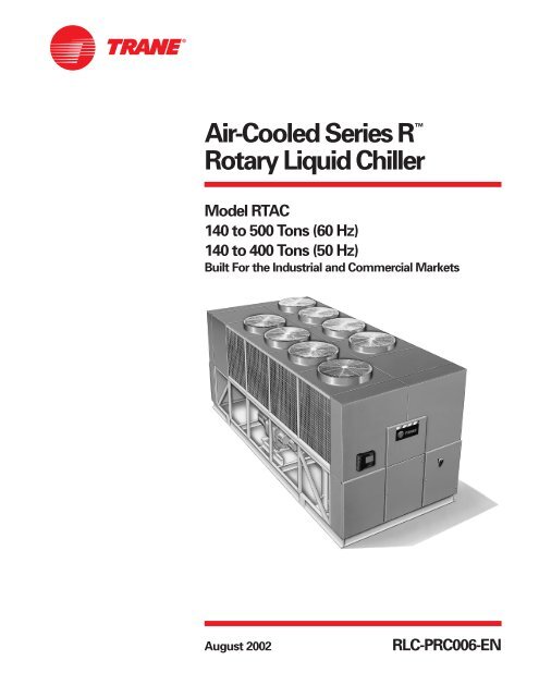
Figure 1 — Cutaway of RTAC <strong>Air</strong>-<strong>Cooled</strong> <strong>Chiller</strong><br />
2<br />
1. Flooded Style Evaporator<br />
2. <strong>Trane</strong> Helical-<strong>Rotary</strong> Compressor<br />
3. Oil Separator<br />
4. Low Sound Condenser Fans<br />
5. Factory Installed and Tested Unit<br />
Controls and Starter<br />
6. Smaller Physical Footprint<br />
© 2002 American Standard Inc. All rights reserved. RLC-PRC006-EN<br />
1<br />
3<br />
4<br />
6<br />
5<br />
5<br />
5
RLC-PRC006-EN<br />
Contents<br />
Introduction<br />
Features and Benefits<br />
Options<br />
Application Considerations<br />
Selection Procedure<br />
Model Number Description<br />
General Data<br />
Performance Adjustment Factors<br />
Performance Data<br />
Full Load Performance<br />
Part Load Performance<br />
Electrical Data<br />
Electrical Connections<br />
Controls<br />
Standalone Controls<br />
Generic Building Automation System Controls<br />
<strong>Trane</strong> Integrated Comfort System Controls<br />
Dimensional Data<br />
Wiring and Layout<br />
Weights<br />
Mechanical Specifications<br />
3<br />
2<br />
4<br />
9<br />
13<br />
14<br />
15<br />
19<br />
20<br />
34<br />
46<br />
51<br />
55<br />
65<br />
74<br />
78
RTAC - Exceeding the Efficiency Standard<br />
60 Hz Full Load Efficiency (EER*) Part Load Efficiency (EER*)<br />
Tonnage ASHRAE 90.1 Standard Efficiency High Efficiency ASHRAE 90.1 Standard Efficiency High Efficiency<br />
140 9.6 9.7 10.4 10.4 13.2 13.6<br />
155 9.6 9.8 10.4 10.4 13.5 13.9<br />
170 9.6 9.9 10.5 10.4 13.2 13.7<br />
185 9.6 9.7 10.3 10.4 13.1 13.5<br />
200 9.6 9.6 10.1 10.4 12.9 13.3<br />
225 9.6 9.6 10.2 10.4 13.2 13.6<br />
250 9.6 9.6 10.1 10.4 12.8 13.0<br />
275 9.6 9.7 10.4 10.4 13.3 13.8<br />
300 9.6 9.6 10.0 10.4 13.7 13.8<br />
350 9.6 9.6 10.4 10.4 13.2 14.5<br />
400 9.6 9.6 10.0 10.4 13.7 13.9<br />
450 9.6 9.6 n/a 10.4 14.0 n/a<br />
500<br />
*COP = EER/3.414<br />
9.6 9.6 n/a 10.4 13.9 n/a<br />
ASHRAE Standard 90.1 and<br />
RTAC World Class Energy<br />
Efficiency…<br />
The importance of energy efficiency<br />
cannot be understated. Fortunately,<br />
ASHRAE has created a guideline<br />
emphasizing its importance.<br />
Nonetheless, energy is often dismissed<br />
as an operational cost over which the<br />
owner has little control. That perception<br />
results in missed opportunities for<br />
energy efficiency, reduced utility bills,<br />
and higher profits. Lower utility bills<br />
directly affect profitability. Every dollar<br />
saved in energy goes directly to the<br />
bottom line. <strong>Trane</strong>’s RTAC is one way to<br />
maximize your profits.<br />
ASHRAE Standard 90.1 & Executive<br />
Order - New technology applied to the<br />
design, controls, and manufacturing<br />
have created excellent efficiency levels in<br />
the RTAC that are helping to push<br />
industry minimums to new heights. All<br />
<strong>Trane</strong> air-cooled chillers meet the new<br />
efficiency levels mandated by ASHRAE<br />
Standard 90.1. This new standard<br />
requires higher efficiencies than past<br />
technologies can deliver. The US Federal<br />
Government has adopted standard 90.1<br />
and, in some cases, requires even higher<br />
efficiencies. Federal Executive Order<br />
mandates energy consuming devices<br />
procured must be in the top 25% of their<br />
class or be at least 10% better than any<br />
product standard for that product. In the<br />
case of chillers, that product standard is<br />
4<br />
Features and<br />
Benefits<br />
ASHRAE 90.1. <strong>Trane</strong>’s RTAC meets and<br />
exceeds the efficiency requirements of<br />
90.1, while the high efficiency RTAC can<br />
meet the “stretch goals” of Executive<br />
Order.<br />
Risk. The US Federal Government has<br />
adopted ASHRAE 90.1, and it’s expected<br />
to be adopted domestically, if not<br />
globally, in the future. Domestic<br />
acceptance has already begun. Make<br />
sure that your chillers as well as your<br />
entire HVAC system complies, or you<br />
may be caught retrofitting your project<br />
with new equipment and paying extra<br />
design dollars if the code is adopted<br />
during construction.<br />
Precise Capacity Control. <strong>Trane</strong>’s<br />
patented unloading system allows the<br />
compressor to modulate infinitely and<br />
exactly match building loads. At the<br />
same time chilled water temperatures<br />
will be maintained within +/- 1/2ºF of<br />
setpoint. Reciprocating and screw<br />
chillers with stepped capacity control do<br />
well to maintain chilled water<br />
temperatures within 2ºF of setpoint.<br />
Stepped control also results in<br />
overcooling your space because rarely<br />
does the capacity of the machine match<br />
the building load. The result can be 10%<br />
higher energy bills. <strong>Trane</strong>’s RTAC<br />
optimizes the part load performance of<br />
your machine for energy efficiency,<br />
precise control for process applications,<br />
and your personal comfort regardless of<br />
the weather outside.<br />
RLC-PRC006-EN
Excellent Reliability…<br />
A buildings environment is expected to<br />
be comfortable. When it is, no one says<br />
a word. If it’s not… that’s a different<br />
story. The same is true with chillers. No<br />
one ever talks about chillers, yet alone<br />
compressors, until they fail, and tenants<br />
are uncomfortable and productivity is<br />
lost. <strong>Trane</strong>’s helical rotary compressors<br />
have a first year reliability rate of over<br />
99%, which means our chillers stay<br />
running when you need them.<br />
Fewer moving parts. <strong>Trane</strong>’s helical<br />
rotary compressors have only two major<br />
rotating parts: the male and female rotor.<br />
A reciprocating compressor can have<br />
more than 15 times that number of<br />
critical parts. Multiples of pistons, valves,<br />
crankshafts, and connecting rods in a<br />
reciprocating unit all represent different<br />
failure paths for the compressor. In fact,<br />
RLC-PRC006-EN<br />
Features and<br />
Benefits<br />
Figure 2 — Cutaway of a compressor<br />
reciprocating compressors can easily<br />
have a failure rate four times of a helical<br />
rotor. Combine that with two to three<br />
reciprocating compressors for each<br />
helical rotary compressor on chillers of<br />
equal tonnage, and statistics tell you it’s<br />
a matter of time before you lose a<br />
reciprocating compressor.<br />
Robust components. Helical rotary<br />
compressors are precisely machined<br />
using state of the art processes from<br />
solid metal bar stock. Tolerances are<br />
maintained within a micron or less than<br />
a tenth of the diameter of a human hair.<br />
The resulting compressor is a robust yet<br />
highly sophisticated assembly capable of<br />
ingesting liquid refrigerant without risk<br />
of damage. Contrast this to a<br />
reciprocating compressor, which can be<br />
destroyed by a single slug of liquid.<br />
Condenser coils. <strong>Trane</strong>’s condenser<br />
coils are manufactured with the same<br />
philosophy as the compressors; they’re<br />
built to last. Even though manufacturing<br />
processes have allowed thinner and<br />
thinner materials in their assembly, with<br />
obvious material and manufacturing<br />
savings, <strong>Trane</strong>’s coil material did not<br />
change with the RTAC generation of air<br />
cooled chillers. Substantial condenser<br />
fins, that do not require additional<br />
coating in non-corrosive environments,<br />
contribute to the highest reliability<br />
standards for air-cooled chillers in the<br />
industry.<br />
5
6<br />
Features and<br />
Benefits<br />
Simple Installation<br />
Compact Physical Size. The <strong>Trane</strong><br />
Model RTAC chiller averages a 20%<br />
reduction in physical footprint, while<br />
the greatest change is actually 40%<br />
smaller when compared against the<br />
previous design. This improvement<br />
makes the RTAC the smallest air-cooled<br />
chiller in the industry and a prime<br />
candidate for installations that have<br />
space constraints. All physical sizes<br />
were changed without sacrificing the<br />
side clearances needed to supply fresh<br />
airflow without coil starvation.<br />
Close Spacing Installation. The aircooled<br />
<strong>Series</strong> R <strong>Chiller</strong> has the tightest<br />
recommended side clearance in the<br />
industry, four feet for maximum<br />
performance. In situations where<br />
equipment must be installed with less<br />
clearance than recommended, which<br />
frequently occurs in retrofit<br />
applications, restricted airflow is<br />
common. Conventional chillers may<br />
not work at all. However, the air-cooled<br />
<strong>Series</strong> R chiller with Adaptive Control <br />
microprocessor will make as much<br />
chilled water as possible given the<br />
actual installed conditions, stay on line<br />
during unforeseen abnormal<br />
conditions, and optimize the unit<br />
performance. Consult your <strong>Trane</strong> sales<br />
engineer for more details.<br />
Factory Testing Means Trouble-Free<br />
Start-Up. All air-cooled <strong>Series</strong> R chillers<br />
are given a complete functional test at<br />
the factory. This computer-based test<br />
program completely checks the<br />
sensors, wiring, electrical components,<br />
microprocessor function,<br />
communication capability, expansion<br />
valve performance and fans. In<br />
addition, each compressor is run and<br />
tested to verify capacity and efficiency.<br />
Where applicable, each unit is factory<br />
preset to the customer’s design<br />
conditions; an example would be<br />
leaving liquid temperature setpoint.<br />
The result of this test program is that<br />
the chiller arrives at the job site fully<br />
tested and ready for operation.<br />
Factory Installed and Tested Controls/<br />
Options Speed Installation. All <strong>Series</strong> R<br />
chiller options, including main power<br />
supply disconnect, low ambient<br />
control, ambient temperature sensor,<br />
low ambient lockout, communication<br />
interface and ice making controls, are<br />
factory installed and tested. Some<br />
manufacturers send accessories in<br />
pieces to be field installed. With <strong>Trane</strong>,<br />
the customer saves on installation<br />
expense and has assurance that ALL<br />
chiller controls/options have been<br />
tested and will function as intended.<br />
RLC-PRC006-EN
Superior Control with Tracer <strong>Chiller</strong> Controllers<br />
The Adaptive Control microprocessor<br />
system enhances the air-cooled <strong>Series</strong> R<br />
chiller by providing the very latest chiller<br />
control technology. With the Adaptive<br />
Control microprocessor, unnecessary<br />
service calls and unhappy tenants are<br />
avoided. The unit is designed not to trip<br />
or unnecessarily shut down. Only when<br />
the Tracer chiller controllers have<br />
exhausted all possible corrective actions<br />
and the unit is still violating an operating<br />
limit will the chiller shut down. Controls<br />
on other equipment typically shut down<br />
the chiller, usually just when it is needed<br />
the most.<br />
For example:<br />
A typical five-year-old chiller with dirty<br />
coils might trip-out on high pressure<br />
cutout on a 100°F (38°C) day in August. A<br />
hot day is just when comfort cooling is<br />
needed the most. In contrast, the aircooled<br />
<strong>Series</strong> R chiller with an Adaptive<br />
Control microprocessor will stage fans<br />
on, modulate electronic expansion valve,<br />
and modulate slide valve position as it<br />
approaches a high pressure cutout,<br />
thereby keeping the chiller on-line when<br />
you need it the most.<br />
System Options — Ice Storage<br />
<strong>Trane</strong> air-cooled <strong>Series</strong> R <strong>Chiller</strong>s are<br />
well suited for ice production. An aircooled<br />
machine typically switches to ice<br />
production at night. Two things happen<br />
under this assumption. First, the leaving<br />
brine temperature from the evaporator is<br />
lowered to around 22 to 24°F<br />
(-5.5 to –4.4°C). Second, the ambient<br />
temperature has typically dropped about<br />
15 to 20°F (8.3 to 11°C) from the peak<br />
daytime ambient. This effectively places<br />
a lift on the compressors that is similar<br />
to daytime running conditions. The<br />
chiller can operate in lower ambient at<br />
night and successfully produce ice to<br />
supplement the next day’s cooling<br />
demands.<br />
The Model RTAC produces ice by<br />
supplying ice storage tanks with a<br />
constant supply of glycol solution. <strong>Air</strong>cooled<br />
chillers selected for these lower<br />
leaving fluid temperatures are also<br />
RLC-PRC006-EN<br />
Features and<br />
Benefits<br />
selected for efficient production of<br />
chilled fluid at nominal comfort cooling<br />
conditions. The ability of <strong>Trane</strong> chillers to<br />
serve “double duty” in ice production<br />
and comfort cooling greatly reduces the<br />
capital cost of ice storage systems.<br />
When cooling is required, ice chilled<br />
glycol is pumped from the ice storage<br />
tanks directly to the cooling coils. No<br />
expensive heat exchanger is required.<br />
The glycol loop is a sealed system,<br />
eliminating expensive annual chemical<br />
treatment costs. The air-cooled chiller is<br />
also available for comfort cooling duty at<br />
nominal cooling conditions and<br />
efficiencies. The modular concept of<br />
glycol ice storage systems and the<br />
proven simplicity of <strong>Trane</strong> Tracer<br />
controllers allow the successful blend of<br />
reliability and energy saving<br />
performance in any ice storage<br />
application.<br />
The ice storage system is operated in six<br />
different modes: each optimized for the<br />
utility cost of the hour.<br />
1. Provide comfort cooling with chiller<br />
2. Provide comfort cooling with ice<br />
3. Provide comfort cooling with ice and<br />
chiller<br />
4. Freeze ice storage<br />
5. Freeze ice storage when comfort<br />
cooling is required<br />
6. Off<br />
Figure 3 — Ice Storage Demand Cost Savings<br />
Tracer optimization software controls<br />
operation of the required equipment and<br />
accessories to easily transition from one<br />
mode of operation to another. For<br />
example:<br />
Even with ice storage systems there are<br />
numerous hours when ice is neither<br />
produced or consumed, but saved. In<br />
this mode the chiller is the sole source of<br />
cooling. For example, to cool the<br />
building after all ice is produced but<br />
before high electrical demand charges<br />
take effect, Tracer sets the air-cooled<br />
chiller leaving fluid setpoint to its most<br />
efficient setting and starts the chiller,<br />
chiller pump, and load pump.<br />
When electrical demand is high, the ice<br />
pump is started and the chiller is either<br />
demand limited or shut down<br />
completely. Tracer controls have the<br />
intelligence to optimally balance the<br />
contribution of ice and chiller in meeting<br />
the cooling load.<br />
The capacity of the chiller plant is<br />
extended by operating the chiller and ice<br />
in tandem. Tracer rations the ice,<br />
augmenting chiller capacity while<br />
reducing cooling costs. When ice is<br />
produced, Tracer will lower the aircooled<br />
chiller leaving fluid setpoint and<br />
start the chiller, ice and chiller pumps,<br />
and other accessories. Any incidental<br />
loads that persist while producing ice<br />
can be addressed by starting the load<br />
pump and drawing spent cooling fluid<br />
from the ice storage tanks.<br />
For specific information on ice storage<br />
applications, contact your local <strong>Trane</strong><br />
sales office.<br />
7
High Efficiency/Performance Option<br />
This option provides oversized heat<br />
exchangers for two purposes. One, it<br />
allows the unit to be more energy<br />
efficient. Two, the unit will have<br />
enhanced operation in high ambient<br />
conditions.<br />
Low Temperature Brine<br />
The hardware and software on the unit<br />
are factory set to handle low<br />
temperature brine applications (less than<br />
40°F/4.4°C).<br />
Ice Making<br />
The unit controls are factory set to<br />
handle ice making for thermal storage<br />
applications.<br />
Tracer/Summit Communication<br />
Interface<br />
Permits bi-directional communication to<br />
the <strong>Trane</strong> Integrated Comfort system.<br />
LonTalk Communications Interface LCI-C<br />
Provides the LonMark chiller profile<br />
inputs/outputs for use with a generic<br />
building automation system.<br />
Remote input options<br />
Permits remote chilled liquid setpoint,<br />
remote current limit setpoint, or both by<br />
accepting a 4-20 mA or 2-10 Vdc analog<br />
signal.<br />
Remote output options<br />
Permits alarm relay outputs, ice making<br />
outputs, or both.<br />
Architectural Louvered Panels<br />
Louvered panels cover the complete<br />
condensing coil and service area<br />
beneath the condenser.<br />
Coil Protection<br />
Louvered panels protect the condenser<br />
coils only.<br />
8<br />
Features and<br />
Benefits<br />
Access Protection<br />
A coated wire mesh that covers the<br />
access area under the condenser coils.<br />
Wye-Delta Compressor Start Type<br />
This option provides a reduced inrush<br />
starter. Wye-Delta starters are standard<br />
on 200-230 volt machines.<br />
Condenser Corrosion Protection<br />
Copper fins and CompleteCoat are<br />
available on all size units for corrosion<br />
protection. Job site conditions should be<br />
matched with the appropriate condenser<br />
fin materials to inhibit coil corrosion and<br />
ensure extended equipment life. The<br />
CompleteCoat option provides fully<br />
assembled coils with a flexible dip and<br />
bake epoxy coating.<br />
TEAO Condenser Fan Motors<br />
Totally enclosed air-over (TEAO) motors<br />
completely seal the motor windings to<br />
prevent exposure to ambient conditions.<br />
Low Ambient Option<br />
The low ambient option provides special<br />
control logic and variable frequency<br />
drives on the condenser fan circuits to<br />
permit low temperature start-up and<br />
operation down to 0°F (-18°C).<br />
Single/Dual Incoming Power Line<br />
Connection<br />
Single or dual points of termination are<br />
available for incoming power line<br />
connections*. Units with 3-4<br />
compressors must order circuit breakers<br />
with the single point connection option.<br />
*Some restrictions may apply.<br />
Convenience Outlet<br />
Provides a 15 amp, 115 volt (60 Hz)<br />
convenience outlet on the unit.<br />
Remote Evaporator<br />
The remote evaporator option is<br />
available on the RTAC 140-250 ton units.<br />
This option provides a pre-engineered<br />
method of installing the evaporator and<br />
all related components indoors.<br />
Remote evaporator installations allow<br />
the water loop to remain indoors to<br />
prevent freezing, thus eliminating the<br />
addition of glycol to the system and the<br />
resulting performance degradation.<br />
Options<br />
High Ambient Option<br />
The high ambient option consists of<br />
special control logic to permit high<br />
ambient (up to 125°F/51°C) operation.<br />
This option offers the best performance<br />
when coupled with the high efficiency<br />
performance option.<br />
Non-Fused Power Disconnect Switch<br />
The non-fused molded case disconnect<br />
switch (UL approved) is used to<br />
disconnect the chiller from main power<br />
and comes pre-wired from the factory<br />
with terminal block power connections.<br />
The external operator handle is lockable.<br />
Circuit Breaker<br />
A HACR rated molded case capacity<br />
circuit breaker (UL approved) is<br />
available. The circuit breaker can also be<br />
used to disconnect the chiller from main<br />
power with a through-the-door handle<br />
and comes pre-wired from the factory<br />
with terminal block power connections.<br />
The external operator handle is lockable.<br />
Neoprene Isolators<br />
Isolators provide isolation between<br />
chiller and structure to help eliminate<br />
vibration transmission. Neoprene<br />
isolators are more effective and<br />
recommended over spring isolators.<br />
Flange Kit<br />
Provides a raised-face flange kit that<br />
converts the grooved pipe evaporator<br />
water connections to flange connectors.<br />
RLC-PRC006-EN
Important<br />
Certain application constraints should be<br />
considered when sizing, selecting and<br />
installing <strong>Trane</strong> air-cooled <strong>Series</strong> R<br />
chillers. Unit and system reliability is<br />
often dependent upon proper and<br />
complete compliance with these<br />
considerations. When the application<br />
varies from the guidelines presented, it<br />
should be reviewed with your local<br />
<strong>Trane</strong> sales engineer.<br />
Unit Sizing<br />
Unit capacities are listed in the<br />
performance data section. Intentionally<br />
over-sizing a unit to assure adequate<br />
capacity is not recommended. Erratic<br />
system operation and excessive<br />
compressor cycling are often a direct<br />
result of an oversized chiller. In addition,<br />
an oversized unit is usually more<br />
expensive to purchase, install, and<br />
operate. If over-sizing is desired,<br />
consider using multiple units.<br />
Water Treatment<br />
Dirt, scale, products of corrosion and<br />
other foreign material will adversely<br />
affect heat transfer between the water<br />
and system components. Foreign matter<br />
in the chilled water system can also<br />
increase pressure drop and<br />
consequently, reduce water flow. Proper<br />
water treatment must be determined<br />
locally, depending on the type of system<br />
and local water characteristics. Neither<br />
salt nor brackish water is recommended<br />
for use in <strong>Trane</strong> air-cooled <strong>Series</strong> R<br />
chillers. Use of either will lead to a<br />
shortened life to an indeterminable<br />
degree. The <strong>Trane</strong> Company encourages<br />
RLC-PRC006-EN<br />
Application<br />
Considerations<br />
the employment of a reputable water<br />
treatment specialist, familiar with local<br />
water conditions, to assist in this<br />
determination and in the establishment<br />
of a proper water treatment program.<br />
Effect Of Altitude On Capacity<br />
<strong>Air</strong>-cooled <strong>Series</strong> R chiller capacities<br />
given in the performance data tables are<br />
for use at sea level. At elevations<br />
substantially above sea level, the<br />
decreased air density will reduce<br />
condenser capacity and, therefore, unit<br />
capacity and efficiency.<br />
Ambient Limitations<br />
<strong>Trane</strong> air-cooled <strong>Series</strong> R chillers are<br />
designed for year-round operation over<br />
a range of ambient temperatures. The<br />
Model RTAC chiller will operature as<br />
standard in ambient temperatures of 25<br />
to 115°F/-4 to 46°C. With the low<br />
ambient option, these units will operate<br />
down to 0°F/-18°C. If an ambient<br />
temperature as high as 125°F/51°C is the<br />
basis for design, the high ambient option<br />
will permit the chiller to run without<br />
going into a limiting condition. For<br />
installations in areas with large ambient<br />
differences, the wide ambient option will<br />
allow the chiller to perform uninhibited<br />
from 0 to 125°F/-18 to 51°C. For<br />
operation outside these ranges, contact<br />
the local <strong>Trane</strong> sales office.<br />
Figure 4 — GPM Out of Range System Layout<br />
Water Flow Limits<br />
The minimum and maximum water flow<br />
rates are given in Tables G-1 and G-2.<br />
Evaporator flow rates below the<br />
tabulated values will result in laminar<br />
flow causing freeze-up problems,<br />
scaling, stratification and poor control.<br />
Flow rates exceeding those listed may<br />
result in excessive tube erosion.<br />
Flow Rates out of Range<br />
Many process cooling jobs require flow<br />
rates that cannot be met with the<br />
minimum and maximum published<br />
values for the Model RTAC evaporator. A<br />
simple piping change can alleviate this<br />
problem. For example: A plastic injection<br />
molding process requires 80 gpm<br />
[5.1 l/s] of 50°F [10°C] water and returns<br />
that water at 60°F [15.6°C]. The selected<br />
chiller can operate at these<br />
temperatures, but has a minimum flow<br />
rate of 120 gpm [7.6 l/s]. The system<br />
layout in Figure 4 can satisfy the process.<br />
Flow Control<br />
<strong>Trane</strong> requires the chilled water flow<br />
control in conjunction with the <strong>Air</strong>-<br />
<strong>Cooled</strong> <strong>Series</strong> R <strong>Chiller</strong> to be done by the<br />
chiller. This will allow the chiller to<br />
protect itself in potentially harmful<br />
conditions.<br />
9
Leaving Water Temperature Limits<br />
<strong>Trane</strong> air-cooled <strong>Series</strong> R chillers have<br />
three distinct leaving water categories:<br />
standard, low temperature, and ice<br />
making. The standard leaving solution<br />
temperature range is 40 to 60°F/4.4 to<br />
15.6°C. Low temperature machines<br />
produce leaving liquid temperatures less<br />
than 40°F/4.4°C. Since liquid supply<br />
temperature setpoints less than<br />
40°F/4.4°C result in suction temperatures<br />
at or below the freezing point of water, a<br />
glycol solution is required for all low<br />
temperature machines. Ice making<br />
machines have a leaving liquid<br />
temperature range of 20 to 60°F/-6.7 to<br />
15.6°C. Ice making controls include dual<br />
setpoint controls and safeties for ice<br />
making and standard cooling<br />
capabilities. Consult your local <strong>Trane</strong><br />
sales engineer for applications or<br />
selections involving low temperature or<br />
ice making machines. The maximum<br />
water temperature that can be circulated<br />
through an evaporator when the unit is<br />
not operating is 108°F/42°C.<br />
Leaving Water Temperature out of<br />
Range<br />
Many process cooling jobs require<br />
temperature ranges that cannot be met<br />
with the minimum and maximum<br />
published values for the Model RTAC<br />
evaporator. A simple piping change can<br />
alleviate this problem. For example: A<br />
laboratory load requires 120 gpm<br />
[7.6 l/s] of water entering the process at<br />
85°F [29.4°C] and returning at 95°F<br />
[35°C]. The accuracy required is better<br />
than the cooling tower can give. The<br />
selected chiller has adequate capacity,<br />
but a maximum leaving chilled water<br />
temperature of 60°F [15.6°C].<br />
In Figure 5, both the chiller and process<br />
flow rates are equal. This is not<br />
necessary. For example, if the chiller had<br />
a higher flow rate, there would simply be<br />
more water bypassing and mixing with<br />
warm water.<br />
10<br />
Application<br />
Considerations<br />
Figure 5 — Temperature Out of Range System Layout<br />
Supply Water Temperature Drop<br />
The performance data for the <strong>Trane</strong> aircooled<br />
<strong>Series</strong> R chiller is based on a<br />
chilled water temperature drop of 10°F/<br />
5.6°C. Chilled water temperature drops<br />
from 6 to 18°F/ 3.3 to 10°C may be used<br />
as long as minimum and maximum<br />
water temperatures and flow rates are<br />
not violated. Temperature drops outside<br />
this range are beyond the optimum<br />
range for control and may adversely<br />
affect the microcomputer’s ability to<br />
maintain an acceptable supply water<br />
temperature range. Further, temperature<br />
drops of less than 6°F/3.3°C may result in<br />
inadequate refrigerant superheat.<br />
Sufficient superheat is always a primary<br />
concern in any refrigerant system and is<br />
especially important in a package chiller<br />
where the evaporator is closely coupled<br />
to the compressor. When temperature<br />
drops are less than 6°F/3.3°C, an<br />
evaporator runaround loop may be<br />
required.<br />
Variable Flow in the Evaporator<br />
An attractive chilled water system option<br />
may be a variable primary flow (VPF)<br />
system. VPF systems present building<br />
owners with several cost-saving benefits<br />
that are directly related to the pumps.<br />
The most obvious cost savings result<br />
from eliminating the secondary<br />
distribution pump, which in turn avoids<br />
the expense incurred with the associated<br />
piping connections (material, labor),<br />
electrical service, and variable-frequency<br />
drive. Building owners often cite pumprelated<br />
energy savings as the reason that<br />
prompted them to install a VPF system.<br />
With the help of a software analysis tool<br />
such as System Analyzer , TRACE , or<br />
DOE-2, you can determine whether the<br />
anticipated energy savings justify the<br />
use of variable primary flow in a<br />
particular application. It may also be<br />
easier to apply variable primary flow in<br />
an existing chilled-water plant. Unlike the<br />
“decoupled” system design, the bypass<br />
can be positioned at various points in the<br />
chilled-water loop and an additional<br />
pump is unnecessary. The evaporator on<br />
the Model RTAC can withstand up to 50<br />
percent water flow reduction as long as<br />
this flow is equal to or above the<br />
minimum flow rate requirements. The<br />
microprocessor and capacity control<br />
algorithms are designed to handle a<br />
maximum of 10% change in water flow<br />
rate per minute in order to maintain ±<br />
0.5°F leaving evaporator temperature<br />
control.<br />
RLC-PRC006-EN
Ice Storage Provides Reduced Electrical<br />
Demand<br />
An ice storage system uses a standard<br />
chiller to make ice at night when utilities<br />
charge less for electricity. The ice<br />
supplements or even replaces<br />
mechanical cooling during the day when<br />
utility rates are at their highest. This<br />
reduced need for cooling results in big<br />
utility cost savings.<br />
Another advantage of ice storage is<br />
standby cooling capacity. If the chiller is<br />
unable to operate, one or two days of ice<br />
may still be available to provide cooling.<br />
In that time the chiller can be running<br />
again before building occupants feel any<br />
loss of comfort.<br />
Figure 6 — Water Piping Recommendations<br />
RLC-PRC006-EN<br />
Drain<br />
Application<br />
Considerations<br />
The <strong>Trane</strong> Model RTAC chiller is uniquely<br />
suited to low temperature applications<br />
like ice storage because of the ambient<br />
relief experienced at night. This allows<br />
the Model RTAC chiller to produce ice<br />
efficiently, with less stress on the<br />
machine.<br />
Simple and smart control strategies are<br />
another advantage the Model RTAC<br />
chiller offers for ice storage applications.<br />
<strong>Trane</strong> Tracer building management<br />
systems can actually anticipate how<br />
much ice needs to be made at night and<br />
operate the system accordingly. The<br />
controls are integrated right into the<br />
chiller. Two wires and preprogrammed<br />
software dramatically reduce field<br />
installation cost and complex<br />
programming.<br />
Vents Valved<br />
Pressure<br />
Gage<br />
Union<br />
Elastomeric<br />
Vibration Flow Switch<br />
Eliminator (Optional)<br />
Gate Valve<br />
Balancing Valve<br />
Union<br />
Typical Water Piping<br />
All building water piping must be<br />
flushed prior to making the final<br />
connections to the chiller. To reduce heat<br />
loss and prevent condensation,<br />
insulation should be installed. Expansion<br />
tanks are also usually required so that<br />
chilled water volume changes can be<br />
accommodated. A typical piping<br />
arrangement is shown in Figure 6.<br />
Elastomeric<br />
Vibration<br />
Eliminator Water<br />
Strainer Gate<br />
Valve<br />
11
12<br />
Application<br />
Considerations<br />
Short Water Loops<br />
The proper location of the temperature<br />
control sensor is in the supply (outlet)<br />
water connection or pipe. This location<br />
allows the building to act as a buffer and<br />
assures a slowly changing return water<br />
temperature. If there is not a sufficient<br />
volume of water in the system to provide<br />
an adequate buffer, temperature control<br />
can be lost, resulting in erratic system<br />
operation and excessive compressor<br />
cycling. A short water loop has the same<br />
effect as attempting to control from the<br />
building return water. Typically, a twominute<br />
water loop is sufficient to prevent<br />
problems. Therefore, as a guideline,<br />
ensure the volume of water in the<br />
evaporator loop equals or exceeds two<br />
times the evaporator flow rate. For a<br />
rapidly changing load profile, the<br />
amount of volume should be increased.<br />
To prevent the effect of a short water<br />
loop, the following items should be<br />
given careful consideration: A storage<br />
tank or larger header pipe to increase the<br />
volume of water in the system and,<br />
therefore, reduce the rate of change of<br />
the return water temperature.<br />
Applications Types<br />
Comfort cooling.<br />
Industrial process cooling.<br />
Ice/thermal storage.<br />
Low temperature process cooling.<br />
Figure 7 — Unit Isolation Recommendations<br />
Flex Conduit<br />
Control Power<br />
Concrete Base<br />
Typical Unit Installation<br />
Outdoor HVAC equipment must be<br />
located to minimize noise and vibration<br />
transmission to the occupied spaces of<br />
the building structure it serves. If the<br />
equipment must be located in close<br />
proximity to a building, it could be<br />
placed next to an unoccupied space such<br />
as a storage room, mechanical room,<br />
etc. It is not recommended to locate the<br />
equipment near occupied, sound<br />
sensitive areas of the building or near<br />
windows. Locating the equipment away<br />
from structures will also prevent sound<br />
reflection, which can increase levels at<br />
property lines, or other sensitive points.<br />
When physically isolating the unit from<br />
structures, it is a good idea to not use<br />
rigid supports, and to eliminate any<br />
metal-to-metal or hard material contact,<br />
when possible. This includes replacing<br />
spring or metal weave isolation with<br />
elastomeric isolators. Figure 7 illustrates<br />
isolation recommendations for the<br />
RTAC.<br />
Neoprene<br />
Isolators<br />
Flex Conduit<br />
Power Wiring<br />
Elastomeric<br />
Vibration<br />
Eliminators<br />
Avoid using the<br />
chiller to support<br />
chiller water<br />
piping.<br />
RLC-PRC006-EN
RLC-PRC006-EN<br />
Selection<br />
Procedure<br />
The chiller capacity tables cover the<br />
most frequently encountered leaving<br />
liquid temperatures. The tables reflect a<br />
10°F/5.6°C temperature drop through the<br />
evaporator. For other temperature drops,<br />
apply the appropriate Performance Data<br />
Adjustment Factors from Table A-1. For<br />
chilled brine selections, contact your<br />
local <strong>Trane</strong> sales engineer. To select a<br />
<strong>Trane</strong> air-cooled <strong>Series</strong> R chiller, the<br />
following information is required:<br />
1<br />
Design load in tons of refrigeration<br />
2<br />
Design chilled water temperature drop<br />
3<br />
Design leaving chilled water temperature<br />
4<br />
Design ambient temperature<br />
Evaporator flow rates can be determined<br />
by using the following formulas:<br />
GPM = (Tons x 24) / Temperature Drop<br />
(Degrees F)<br />
OR<br />
L/S = (kW (Capacity) x .239) /<br />
Temperature Drop (Degrees C)<br />
NOTE: Flow rates must fall within the<br />
limits specified in Tables G-1 and G-2 (for<br />
GPM or for l/s).<br />
Selection Example<br />
Given:<br />
Required System Load = 140 Tons<br />
Leaving Chilled Water Temperature<br />
(LCWT) = 44°F Chilled Water<br />
Temperature Drop = 10°F Design<br />
Ambient Temperature = 95°F<br />
Evaporator Fouling Factor = 0.0001<br />
1<br />
To calculate the required chilled water<br />
flow rate we use the formula given<br />
below:<br />
GPM = (140 Tons x 24) / 10°F = 336 GPM<br />
2<br />
From Table P-1 (RTAC performance<br />
data), an RTAC 140 standard at the given<br />
conditions will produce 140.8 tons with<br />
compressor power input of 158.5 kW<br />
and a unit EER of 9.7.<br />
3<br />
To determine the evaporator pressure<br />
drop use the flow rate (GPM) and<br />
pressure drop chart on page 16. Entering<br />
the curve at 336 gpm, the pressure drop<br />
for a nominal 140 standard evaporator is<br />
16 feet.<br />
Minimum Leaving Chilled Water<br />
Temperature Setpoint<br />
The minimum leaving chilled water<br />
temperature setpoint for water is 40°F.<br />
For those applications requiring lower<br />
setpoints, a glycol solution must be<br />
used. Contact the local <strong>Trane</strong> sales<br />
engineer for additional information.<br />
13
1140-500 Tons<br />
Digits 1, 2 — Unit Model<br />
RT <strong>Rotary</strong> <strong>Chiller</strong><br />
Digit 3 — Unit Type<br />
A <strong>Air</strong> <strong>Cooled</strong><br />
Digit 4 — Development Sequence<br />
C Third Sequence<br />
Digit 5, 6 & 7 — Nominal Capacity<br />
140 140 Nominal Tons<br />
155 155 Nominal Tons<br />
170 170 Nominal Tons<br />
185 185 Nominal Tons<br />
200 200 Nominal Tons<br />
225 225 Nominal Tons<br />
250 250 Nominal Tons<br />
275 275 Nominal Tons<br />
300 300 Nominal Tons<br />
350 350 Nominal Tons<br />
375 375 Nominal Tons<br />
400 400 Nominal Tons<br />
450 450 Nominal Tons<br />
500 500 Nominal Tons<br />
Digit 8 — Unit Voltage<br />
A 200/60/3<br />
C 230/60/3<br />
J 380/60/3<br />
D 400/50/3<br />
4 460/60/3<br />
5 575/60/3<br />
Digit 9 – Manufacturing Location<br />
U Water <strong>Chiller</strong> Business Unit,<br />
Pueblo, CO USA<br />
Digit 10, 11 — Design Sequence<br />
CO Factory Input<br />
Digit 12 — Unit Basic Configuration<br />
N Standard efficiency/performance<br />
configuration<br />
H High efficiency/performance<br />
configuration<br />
Digit 13 — Agency Listing<br />
N No agency listing<br />
U UL/CUL listing<br />
Digit 14 — Pressure vessel code<br />
A ASME pressure vessel code<br />
Digit 15 — Evaporator temp range<br />
F Standard 40-60 deg F leaving temp<br />
G Low (
RLC-PRC006-EN<br />
General Data<br />
Table G-1 — General Data — 140-500 Ton 60 Hz Units - Standard Efficiency<br />
Size 140 155 170 185 200 225 250 275 300 350 400 450 500<br />
Type<br />
Compressor<br />
STD STD STD STD STD STD STD STD STD STD STD STD STD<br />
Quantity (1) 2 2 2 2 2 2 2 3 3 3 4 4 4<br />
85-85 / 100-100 / 120-120 / 100-100 / 120-120 / 120-120 /<br />
Nominal Size (tons)<br />
Evaporator<br />
70/70 85/70 85/85 100/85 100/100 120/100 120/120 100 100 100 100-100 100-100 120-120<br />
Water Storage (Gallons) 35 38 40 42 44 47 50 60 66 71 81 87 93<br />
(Liters) 132 141 151 156 163 176 188 227 249 267 304 327 350<br />
Min. Flow (GPM) 170 182 198 215 215 237 259 275 308 342 457 501 545<br />
(L/Sec) 11 11 13 14 14 15 16 17 20 22 29 32 34<br />
Max. Flow (GPM) 525 606 687 626 767 848 929 908 1070 1192 1656 1818 1979<br />
Condenser<br />
(L/Sec) 33 38 43 39 48 54 59 57 68 75 105 115 125<br />
Qty of Coils 4 4 4 4 4 4 4 8 8 8 8 8 8<br />
Coil Length (inches) 156/156 180/156 180/180 216/180 216/216 252/216 252/252 180/108 216/108 252/108 216/216 252/216 252/252<br />
Coil Height<br />
(mm)<br />
(inches)<br />
3962/3962<br />
42<br />
4572/3962<br />
42<br />
4572/4572<br />
42<br />
5486/4572<br />
42<br />
5486/5486<br />
42<br />
6401/5486<br />
42<br />
6401/6401<br />
42<br />
4572/2743<br />
42<br />
5486/2743<br />
42<br />
6401/4572<br />
42<br />
5486/5486<br />
42<br />
6401/5486 6401/6401<br />
42 42<br />
(mm) 1067 1067 1067 1067 1067 1067 1067 1067 1067 1067 1067 1067 1067<br />
Fins/Ft 192 192 192 192 192 192 192 192 192 192 192 192 192<br />
Number of Rows<br />
Condenser Fans<br />
3 3 3 3 3 3 3 3 3 3 3 3 3<br />
Quantity (1) 4/4 5/4 5/5 6/5 6/6 7/6 7/7 10/6 12/6 14/6 12/12 14/12 14/14<br />
Diameter (inches) 30 30 30 30 30 30 30 30 30 30 30 30 30<br />
(mm) 762 762 762 762 762 762 762 762 762 762 762 762 762<br />
Total <strong>Air</strong>flow (cfm) 77000 84542 92087 101296 110506 119725 128946 147340 165766 184151 221016 239456 257991<br />
(m^3/hr) 130811 143623 156441 172086 187732 203394 219059 250307 281610 312843 375471 406797 438285<br />
Nominal fan speed rpm 1140 1140 1140 1140 1140 1140 1140 1140 1140 1140 1140 1140 1140<br />
rps 19 19 19 19 19 19 19 19 19 19 19 19 19<br />
Tip Speed (ft/min) 8954 8954 8954 8954 8954 8954 8954 8954 8954 8954 8954 8954 8954<br />
M/S 45 45 45 45 45 45 45 45 45 45 45 45 45<br />
Motor Nominal (Ea) HP 1.5 1.5 1.5 1.5 1.5 1.5 1.5 1.5 1.5 1.5 1.5 1.5 1.5<br />
kW 1.5 1.5 1.5 1.5 1.5 1.5 1.5 1.5 1.5 1.5 1.5 1.5 1.5<br />
Min Starting/Oper Ambient (2)<br />
Std Unit (Deg F) 25 25 25 25 25 25 25 25 25 25 25 25 25<br />
(Deg C) -3.9 -3.9 -3.9 -3.9 -3.9 -3.9 -3.9 -3.9 -3.9 -3.9 -3.9 -3.9 -3.9<br />
Low Ambient (Deg F) 0 0 0 0 0 0 0 0 0 0 0 0 0<br />
General Unit<br />
(Deg C) -17.8 -17.8 -17.8 -17.8 -17.8 -17.8 -17.8 -17.8 -17.8 -17.8 -17.8 -17.8 -17.8<br />
Refrigerant<br />
No. of Independent<br />
HFC-134a HFC-134a HFC-134a HFC-134a HFC-134a HFC-134a HFC-134a HFC-134a HFC-134a HFC-134a HFC-134a HFC-134a HFC-134a<br />
Refrigerant Circuits 2 2 2 2 2 2 2 2 2 2 2 2 2<br />
% Min. Load 15 15 15 15 15 15 15 15 15 15 15 15 15<br />
Refrigerant Charge (1) (lb) 145/145 155/145 155/155 220/210 220/220 230/220 230/230 335/195 385/195 430/215 385/385 430/385 430/430<br />
(kg) 66/66 70/66 70/70 100/95 100/100 104/100 104/104 152/88 175/88 195/97 175/175 195/175 195/195<br />
Oil Charge (1) (lb) 14.4/14.4 15.3/14.4 15.3/15.3 21.8/20.8 21.8/21.8 22.8/21.8 22.8/22.8 33.7/20.3 39.1/20.3 42.6/24.3 39.1/39.1 42.6/39.1 42.6/42.6<br />
(kg) 54.5/54.5 57.9/54.5 57.9/57.9 82.5/78.7 82.5/82.5 86.3/82.5 86.3/86.3 127.6/76.8 148/76.8 161.2/92 148/148 161.2/148 161.2/161.2<br />
Notes:<br />
1. Data containing information on two circuits shown as follows: CKT 1/CKT 2<br />
2. Minimum start-up/operating ambient based on a 5 mph wind across the condenser<br />
15
Table G-1 —General Data — 140-400 Ton 60 Hz Units - High Efficiency<br />
Size 140 155 170 185 200 225 250 275 300 350 400<br />
Type<br />
Compressor<br />
HIGH HIGH HIGH HIGH HIGH HIGH HIGH HIGH HIGH HIGH HIGH<br />
Quantity (1) 2 2 2 2 2 2 2 3 3 4 4<br />
100-100 / 85-85 / 100-100 /<br />
Nominal Size (tons)<br />
Evaporator<br />
70/70 85/70 85/85 100/85 100/100 120/100 120/120 85-85/100 100 85-85 100-100<br />
Water Storage (Gallons) 40 42 43 47 50 50 50 71 71 81 93<br />
(Liters) 151 156 163 176 188 188 188 267 267 304 351<br />
Min. Flow (GPM) 198 215 215 237 259 259 259 342 342 457 545<br />
(L/Sec) 13 14 14 15 16 16 16 22 22 29 34<br />
Max. Flow (GPM) 687 626 767 848 929 929 929 1192 1192 1656 1979<br />
Condenser<br />
(L/Sec) 43 39 48 54 59 59 59 75 75 105 125<br />
Qty of Coils 4 4 4 4 4 8 8 8 8 8 8<br />
Coil Length (inches) 180/180 216/180 216/216 252/216 252/252 144/144 180/108 216/144 252/144 216/216 252/252<br />
(mm) 4572/4572 5486/4572 5486/5486 6401/5486 6401/6401 3658/3658 4572/2743 5486/3658 6401/3658 5486/5486 6401/6401<br />
Coil Height (inches) 42 42 42 42 42 42 42 42 42 42 42<br />
(mm) 1067 1067 1067 1067 1067 1067 1067 1067 1067 1067 1067<br />
Fins/Ft 192 192 192 192 192 192 192 192 192 192 192<br />
Number of Rows<br />
Condenser Fans<br />
3 3 3 3 3 3 3 3 3 3 3<br />
Quantity (1) 5/5 6/5 6/6 7/6 7/7 8/6 8/8 12/6 14/6 12/12 14/14<br />
Diameter (inches) 30 30 30 30 30 30 30 30 30 30 30<br />
(mm) 762 762 762 762 762 762 762 762 762 762 762<br />
Total <strong>Air</strong>flow (cfm) 91993 101190 110387 119598 128812 136958 147242 173733 192098 220778 257626<br />
(m^3/hr) 156281 171906 187530 203178 218831 232670 250141 295145 326344 375066 437665<br />
Nominal fan speed rpm 1140 1140 1140 1140 1140 1140 1140 1140 1140 1140 1140<br />
rps 19 19 19 19 19 19 19 19 19 19 19<br />
Tip Speed (ft/min) 8954 8954 8954 8954 8954 8954 8954 8954 8954 8954 8954<br />
M/S 45 45 45 45 45 45 45 45 45 45 45<br />
Motor Nominal (Ea) HP 1.5 1.5 1.5 1.5 1.5 1.5 1.5 1.5 1.5 1.5 1.5<br />
kW 1.5 1.5 1.5 1.5 1.5 1.5 1.5 1.5 1.5 1.5 1.5<br />
Min Starting/Oper Ambient (2)<br />
Std Unit (Deg F) 25 25 25 25 25 25 25 25 25 25 25<br />
(Deg C) -3.9 -3.9 -3.9 -3.9 -3.9 -3.9 -3.9 -3.9 -3.9 -3.9 -3.9<br />
Low Ambient (Deg F) 0 0 0 0 0 0 0 0 0 0 0<br />
General Unit<br />
(Deg C) -17.8 -17.8 -17.8 -17.8 -17.8 -17.8 -17.8 -17.8 -17.8 -17.8 -17.8<br />
Refrigerant<br />
No. of Independent<br />
HFC-134a HFC-134a HFC-134a HFC-134a HFC-134a HFC-134a HFC-134a HFC-134a HFC-134a HFC-134a HFC-134a<br />
Refrigerant Circuits 2 2 2 2 2 2 2 2 2 2 2<br />
% Min. Load 15 15 15 15 15 15 15 15 15 15 15<br />
Refrigerant Charge (1) (lb) 155/155 220/210 220/220 230/220 230/230 240/240 240/240 385/215 430/215 385/385 430/430<br />
(kg) 70/70 100/95 100/100 104/100 104/104 109/109 109/109 175/97 195/97 175/175 195/195<br />
Oil Charge (1) (lb) 15.3/15.3 21.8/20.8 21.8/21.8 22.8/21.8 22.8/22.8 24.8/24.8 24.8/24.8 39.1/24.3 42.6/24.3 39.1/39.1 42.6/42.6<br />
Notes:<br />
(kg) 57.9/57.9 82.5/78.7 82.5/82.5 86.3/82.5 86.3/86.3 93.9/93.9 93.9/93.9 148/92 161.2/92 148/148 161.2/161.2<br />
1. Data containing information on two circuits shown as follows: CKT 1/CKT 2<br />
2. Minimum start-up/operating ambient based on a 5 mph wind across the condenser<br />
16<br />
General Data<br />
RLC-PRC006-EN
RLC-PRC006-EN<br />
General Data<br />
Table G-2 —General Data — 140-400 Ton 50 Hz Units-Standard Efficiency<br />
Size 140 155 170 185 200 250 275 300 350 375 400<br />
Type<br />
Compressor<br />
STD STD STD STD STD STD STD STD STD STD STD<br />
Quantity (1) 2 2 2 2 2 3 3 3 4 4 4<br />
70-70 / 85-85 / 100-100 / 85-85 / 100-100 / 100-100 /<br />
Nominal Size (tons)<br />
Evaporator<br />
70/70 85/70 85/85 100/85 100/100 100 100 1100 85-85 85-85 100-100<br />
Water Storage (Gallons) 35 38 40 42 44 54 60 66 71 73 81<br />
(Liters) 132 141 151 156 163 205 227 249 265 276 304<br />
Min. Flow (GPM) 171 182 198 215 215 242 275 308 457 501 545<br />
(L/Sec) 11 11 13 14 14 15 17 20 29 32 34<br />
Max. Flow (GPM) 525 606 684 626 767 747 909 1070 1313 1454 1656<br />
Condenser<br />
(L/Sec) 33 38 43 39 48 47 57 68 83 92 105<br />
Qty of Coils 4 4 4 4 4 8 8 8 8 8 8<br />
Coil Length (inches) 156/156 180/156 180/180 216/180 216/216 156/108 180/108 216/108 180/180 216/180 252/216<br />
(mm) 3962/3962 4572/3962 4572/4572 5486/4572 5486/5486 3962/4572 4572/2743 5486/2743 4572/4572 5486/4572 6401/5486<br />
Coil Height (inches) 42 42 42 42 42 42 42 42 42 42 42<br />
(mm) 1067 1067 1067 1067 1067 1067 1067 1067 1067 1067 1067<br />
Fins/Ft 192 192 192 192 192 192 192 192 192 192 192<br />
Number of Rows<br />
Condenser Fans<br />
3 3 3 3 3 3 3 3 3 3 3<br />
Quantity (1) 4/4 5/4 5/5 6/5 6/6 8/6 10/6 12/6 10/10 12/10 12/12<br />
Diameter (inches) 30 30 30 30 30 30 30 30 30 30 30<br />
(mm) 762 762 762 762 762 762 762 762 762 762 762<br />
Total <strong>Air</strong>flow (cfm) 63346 69507 75671 83236 90803 108698 121056 136210 151332 166467 181611<br />
(m^3/hr) 107615 118081 128553 141405 154260 184661 205655 231399 257089 282801 308528<br />
Nominal fan speed rpm 950 950 950 950 950 950 950 950 950 950 950<br />
rps 15.8 15.8 15.8 15.8 15.8 15.8 15.8 15.8 15.8 15.8 15.8<br />
Tip Speed (ft/min) 7461 7461 7461 7461 7461 7461 7461 7461 7461 7461 7461<br />
M/S 38 38 38 38 38 38 38 38 38 38 38<br />
Motor Nominal (Ea) HP 1.5 1.5 1.5 1.5 1.5 1.5 1.5 1.5 1.5 1.5 1.5<br />
kW 1.5 1.5 1.5 1.5 1.5 1.5 1.5 1.5 1.5 1.5 1.5<br />
Min Starting/Oper Ambient (2)<br />
Std Unit (Deg F) 25 25 25 25 25 25 25 25 25 25 25<br />
(Deg C) -3.9 -3.9 -3.9 -3.9 -3.9 -3.9 -3.9 -3.9 -3.9 -3.9 -3.9<br />
Low Ambient (Deg F) 0 0 0 0 0 0 0 0 0 0 0<br />
General Unit<br />
(Deg C) -17.8 -17.8 -17.8 -17.8 -17.8 -17.8 -17.8 -17.8 -17.8 -17.8 -17.8<br />
Refrigerant<br />
No. of Independent<br />
HFC-134a HFC-134a HFC-134a HFC-134a HFC-134a HFC-134a HFC-134a HFC-134a HFC-134a HFC-134a HFC-134a<br />
Refrigerant Circuits 2 2 2 2 2 2 2 2 2 2 2<br />
% Min. Load 15 15 15 15 15 15 15 15 15 15 15<br />
Refrigerant Charge (1) (lb) 145/145 155/145 155/155 220/210 220/220 305/195 335/195 385/195 335/335 385/335 385/385<br />
(kg) 66/66 70/66 70/70 100/95 100/100 138/88 152/88 175/88 152/152 175/152 175/175<br />
Oil Charge (1) (lb) 14.4/14.4 15.3/14.4 15.3/15.3 21.8/20.8 21.8/21.8 22.8/22.8 33.7/20.3 39.1/20.3 33.7/24.3 39.1/33.7 39.1/39.1<br />
Notes:<br />
(kg) 54.5/54.5 57.9/54.5 57.9/57.9 82.5/78.7 82.5/82.5 86.3/86.3 127.6/76.8 148/76.8 127.6/92 148/127.6 148/148<br />
1. Data containing information on two circuits shown as follows: CKT 1/CKT 2<br />
2. Minimum start-up/operating ambient based on a 5 mph wind across the condenser<br />
17
18<br />
General Data<br />
Table G-2 —General Data — 140-400 Ton 50 Hz Units-High Efficiency<br />
Size 140 155 170 185 200 250 275 300 350 375 400<br />
Type<br />
Compressor<br />
HIGH HIGH HIGH HIGH HIGH HIGH HIGH HIGH HIGH HIGH HIGH<br />
Quantity (1) 2 2 2 2 2 3 3 3 4 4 4<br />
70-70 / 85-85 / 100-100 / 85-85 / 100-100 / 100-100 /<br />
Nominal Size (tons)<br />
Evaporator<br />
70/70 85/70 85/85 100/85 100/100 100 100 100 85-85 85-85 100-100<br />
Water Storage (Gallons) 40 42 44 47 50 66 71 71 81 87 93<br />
(Liters) 151 156 163 176 188 249 267 267 304 327 350<br />
Min. Flow (GPM) 198 215 215 237 259 308 342 342 457 501 545<br />
(L/Sec) 13 14 14 15 16 20 22 22 29 32 34<br />
Max. Flow (GPM) 687 626 767 848 929 1070 1192 1192 1656 1818 1979<br />
Condenser<br />
(L/Sec) 43 39 48 54 59 68 75 75 105 115 125<br />
Qty of Coils 4 4 4 4 4 8 8 8 8 8 8<br />
Coil Length (inches) 180/180 216/180 216/216 252/216 252/252 180/108 216/144 252/144 216/216 252/216 252/252<br />
(mm) 4572/4572 5486/4572 5486/5486 6401/5486 6401/6401 4572/2743 5486/3658 6401/3658 5486/5486 6401/5486 6401/6401<br />
Coil Height (inches) 42 42 42 42 42 42 42 42 42 42 42<br />
(mm) 1067 1067 1067 1067 1067 1067 1067 1067 1067 1067 1067<br />
Fins/Ft 192 192 192 192 192 192 192 192 192 192 192<br />
Number of Rows<br />
Condenser Fans<br />
3 3 3 3 3 3 3 3 3 3 3<br />
Quantity (1) 5/5 6/5 6/6 7/6 7/7 10/6 12/6 14/6 12/12 14/12 14/14<br />
Diameter (inches) 30 30 30 30 30 30 30 30 30 30 30<br />
(mm) 762 762 762 762 762 762 762 762 762 762 762<br />
Total <strong>Air</strong>flow (cfm) 75575 83130 90687 98256 105826 120971 142969 158112 181371 194731 211648<br />
(m^3/hr) 128390 141225 154063 166921 179781 205510 242881 268607 308120 330817 359556<br />
Nominal fan speed rpm 950 950 950 950 950 950 950 950 950 950 950<br />
rps 15.8 15.8 15.8 15.8 15.8 15.8 15.8 15.8 15.8 15.8 15.8<br />
Tip Speed (ft/min) 7461 7461 7461 7461 7461 7461 7461 7461 7461 7461 7461<br />
M/S 38 38 38 38 38 38 38 38 38 38 38<br />
Motor Nominal (Ea) HP 1.5 1.5 1.5 1.5 1.5 1.5 1.5 1.5 1.5 1.5 1.5<br />
kW 1.5 1.5 1.5 1.5 1.5 1.5 1.5 1.5 1.5 1.5 1.5<br />
Min Starting/Oper Ambient (2)<br />
Std Unit (Deg F) 25 25 25 25 25 25 25 25 25 25 25<br />
(Deg C) -3.9 -3.9 -3.9 -3.9 -3.9 -3.9 -3.9 -3.9 -3.9 -3.9 -3.9<br />
Low Ambient (Deg F) 0 0 0 0 0 0 0 0 0 0 0<br />
General Unit<br />
(Deg C) -17.8 -17.8 -17.8 -17.8 -17.8 -17.8 -17.8 -17.8 -17.8 -17.8 -17.8<br />
Refrigerant<br />
No. of Independent<br />
HFC-134a HFC-134a HFC-134a HFC-134a HFC-134a HFC-134a HFC-134a HFC-134a HFC-134a HFC-134a HFC-134a<br />
Refrigerant Circuits 2 2 2 2 2 2 2 2 2 2 2<br />
% Min. Load 15 15 15 15 15 15 15 15 15 15 15<br />
Refrigerant Charge (1) (lb) 155/155 220/210 220/220 230/220 230/230 335/195 385/215 430/215 385/385 430/385 430/430<br />
(kg) 70/70 100/95 100/100 104/100 104/104 152/88 175/97 195/97 175/175 195/175 195/195<br />
Oil Charge (1) (lb) 15.3/15.3 21.8/20.8 21.8/21.8 22.8/21.8 22.8/22.8 33.7/20.3 39.1/24.3 42.6/24.3 39.1/39.1 42.6/39.1 42.6/42.6<br />
Notes:<br />
(kg) 57.9/57.9 82.5/78.7 82.5/82.5 86.3/82.5 86.3/86.3 127.6/76.8 148/92 161/92 148/148 161.2/148 161.2/161.2<br />
1. Data containing information on two circuits shown as follows: CKT 1/CKT 2<br />
2. Minimum start-up/operating ambient based on a 5 mph wind across the condenser<br />
RLC-PRC006-EN
RLC-PRC006-EN<br />
Performance<br />
Data<br />
Table P-1 — Performance Data Adjustment Factors<br />
Chilled Elevation<br />
Fouling Water Sea Level 2000 ft 4000 ft 6000 ft<br />
Factor Temp. CAP GPM KW CAP GPM KW CAP GPM KW CAP GPM KW<br />
0.0001 8 0.997 1.246 0.999 0.987 1.233 1.012 0.975 1.217 1.027 0.960 1.200 1.045<br />
10 1.000 1.000 1.000 0.989 0.989 1.013 0.977 0.977 1.028 0.963 0.963 1.047<br />
12 1.003 0.835 1.001 0.992 0.826 1.014 0.979 0.816 1.030 0.965 0.804 1.048<br />
14 1.004 0.717 1.002 0.993 0.710 1.016 0.981 0.701 1.031 0.966 0.690 1.049<br />
16 1.006 0.629 1.003 0.995 0.622 1.016 0.982 0.614 1.032 0.968 0.605 1.050<br />
0.00025 8 0.982 1.227 0.991 0.972 1.215 1.003 0.961 1.200 1.018 0.947 1.183 1.036<br />
10 0.986 0.985 0.992 0.975 0.975 1.005 0.963 0.963 1.020 0.950 0.950 1.038<br />
12 0.988 0.823 0.994 0.978 0.815 1.006 0.966 0.805 1.022 0.952 0.793 1.040<br />
14 0.991 0.708 0.995 0.980 0.700 1.008 0.968 0.692 1.023 0.954 0.682 1.041<br />
16 0.992 0.621 0.996 0.982 0.614 1.009 0.970 0.606 1.024 0.956 0.598 1.042<br />
Figure P-1 — Evaporator Water Pressure Drop, All Units<br />
Adjustment<br />
Factors<br />
19
Table P-1 — 60 Hz Standard Efficiency Machines in English Units<br />
Condenser Entering <strong>Air</strong> Temperature (F)<br />
85 95 105 115<br />
Evaporator<br />
Leaving Water Unit Size<br />
Temperature (F) Model RTAC Tons kW input EER Tons kW input EER Ton kW input EER Tons kW input EER<br />
140 STD 140.5 139.8 10.9 131.1 152.4 9.4 121.2 166.6 8.0 111.1 182.5 6.7<br />
155 STD 154.4 152.3 11.0 144.2 166.0 9.5 133.6 181.5 8.1 122.7 198.8 6.8<br />
170 STD 168.5 164.8 11.0 157.5 179.7 9.5 146.1 196.5 8.2 134.5 215.2 6.9<br />
185 STD 184.1 183.7 10.8 172.2 199.9 9.4 159.8 218.1 8.0 147.1 238.5 6.8<br />
200 STD 199.8 202.7 10.7 186.9 220.1 9.3 173.5 239.9 7.9 159.6 262.0 6.7<br />
40 225 STD 220.2 222.6 10.7 206.2 241.6 9.3 191.6 263.2 8.0 176.4 287.4 6.8<br />
250 STD 241.1 242.8 10.8 225.9 263.4 9.4 209.9 286.9 8.1 193.4 313.1 6.8<br />
275 STD 267.0 266.8 10.8 250.0 290.4 9.4 232.3 317.0 8.0 213.9 346.7 6.8<br />
300 STD 301.3 320.6 10.6 281.1 348.3 9.2 260.2 379.5 7.8 235.9 408.7 6.6<br />
350 STD 338.7 346.9 10.6 317.5 376.0 9.2 295.3 409.1 7.9 272.2 446.3 6.8<br />
400 STD 400.2 408.4 10.6 374.6 442.8 9.2 347.9 481.9 7.9 320.1 525.8 6.7<br />
450 STD 436.7 449.3 10.6 409.1 487.0 9.2 380.3 529.7 8.0 350.3 577.7 6.8<br />
500 STD 477.2 490.6 10.6 447.3 531.3 9.3 416.0 577.7 8.0 383.4 629.6 6.8<br />
140 STD 145.6 142.7 11.1 135.9 155.4 9.6 125.8 169.7 8.2 115.3 185.7 6.9<br />
155 STD 160.0 155.4 11.1 149.5 169.3 9.6 138.6 184.9 8.2 127.4 202.2 7.0<br />
170 STD 174.6 168.2 11.2 163.3 183.2 9.7 151.6 200.1 8.3 139.6 218.9 7.0<br />
185 STD 190.7 187.6 11.0 178.4 203.9 9.5 165.7 222.3 8.2 152.5 242.8 7.0<br />
200 STD 206.8 207.1 10.8 193.6 224.6 9.4 179.8 244.5 8.1 165.5 266.8 6.9<br />
42 225 STD 228.0 227.6 10.9 213.6 246.8 9.5 198.5 268.5 8.1 182.8 292.9 6.9<br />
250 STD 249.7 248.4 10.9 234.0 269.3 9.5 217.5 292.9 8.2 200.4 319.3 7.0<br />
275 STD 276.5 272.4 11.0 259.0 296.1 9.5 240.8 322.9 8.2 221.9 352.8 7.0<br />
300 STD 311.5 327.8 10.8 290.7 355.8 9.3 269.2 387.2 7.9 237.7 402.9 6.8<br />
350 STD 350.7 354.8 10.7 328.8 384.2 9.4 305.9 417.5 8.1 282.0 454.9 6.9<br />
400 STD 414.3 417.3 10.8 388.0 452.0 9.4 360.5 491.4 8.1 331.9 535.5 6.9<br />
450 STD 452.2 459.5 10.8 423.7 497.5 9.4 394.0 540.6 8.1 363.1 588.9 6.9<br />
500 STD 494.2 502.1 10.8 463.3 543.2 9.4 431.0 589.9 8.1 397.2 642.2 6.9<br />
140 STD 150.8 145.7 11.3 140.8 158.5 9.7 130.4 172.9 8.3 119.6 188.9 7.0<br />
155 STD 165.7 158.6 11.3 154.8 172.6 9.8 143.7 188.3 8.4 132.1 205.7 7.1<br />
170 STD 180.8 171.7 11.4 169.1 186.8 9.9 157.1 203.8 8.5 144.8 222.6 7.2<br />
185 STD 197.4 191.6 11.2 184.7 208.0 9.7 171.6 226.5 8.3 158.1 247.1 7.1<br />
200 STD 214.0 211.6 11.0 200.4 229.2 9.6 186.1 249.3 8.2 171.4 271.7 7.0<br />
44 225 STD 236.0 232.7 11.0 221.1 252.0 9.6 205.5 273.9 8.3 189.3 298.4 7.0<br />
250 STD 258.4 254.2 11.1 242.2 275.2 9.6 225.2 299.0 8.3 207.4 325.6 7.1<br />
275 STD 286.1 278.0 11.2 268.1 302.0 9.7 249.4 328.9 8.3 230.0 359.0 7.1<br />
300 STD 321.8 335.2 10.9 300.4 363.4 9.6 278.2 395.1 8.1 239.3 396.1 6.9<br />
350 STD 362.8 362.8 10.9 340.2 392.5 9.6 316.6 426.1 8.2 291.9 463.7 7.0<br />
400 STD 428.7 426.4 10.9 401.5 461.3 9.6 373.2 501.0 8.2 343.8 545.5 7.0<br />
450 STD 467.9 469.9 10.9 438.5 508.2 9.6 407.9 551.6 8.2 375.9 600.2 7.0<br />
500 STD 511.5 513.8 10.9 479.5 555.3 9.6 446.1 602.4 8.2 411.2 655.0 7.0<br />
20<br />
Performance<br />
Data<br />
Notes:<br />
1. Ratings based on sea level altitude and evaporator fouling factor of 0.00010.<br />
2. Consult <strong>Trane</strong> representative for performance at temperatures outside of the ranges shown.<br />
3. kW input is for compressors only.<br />
4. EER = Energy Efficiency Ratio (Btu/watt-hour). Power inputs include compressors, condenser fans and control power.<br />
5. Ratings are based on an evaporator temperature drop of 10°F.<br />
6. Ambient temperatures 115° F and greater reflect the high ambient condenser option.<br />
7. Interpolation between points is permissible. Extrapolation is not permitted.<br />
8. Rated in accordance with ARI Standard 550/590-98.<br />
Full Load<br />
Performance<br />
RLC-PRC006-EN
RLC-PRC006-EN<br />
Performance<br />
Data<br />
Full Load<br />
Performance<br />
Table P-1 (Continued) — 60 Hz Standard Efficiency Machines in English Units<br />
Condenser Entering <strong>Air</strong> Temperature (F)<br />
85 95 105 115<br />
Evaporator<br />
Leaving Water Unit Size<br />
Temperature (F) Model RTAC Tons kW input EER Tons kW input EER Ton kW input EER Tons kW input EER<br />
140 STD 156.0 148.7 11.4 145.7 161.6 9.9 135.0 176.1 8.5 123.9 192.2 7.2<br />
155 STD 171.4 161.9 11.5 160.3 176.0 10.0 148.8 191.8 8.6 136.9 209.3 7.3<br />
170 STD 187.0 175.2 11.6 175.1 190.4 10.0 162.8 207.5 8.6 150.1 226.5 7.3<br />
185 STD 204.1 195.6 11.3 191.1 212.1 9.9 177.7 230.7 8.5 163.7 251.5 7.2<br />
200 STD 221.2 216.2 11.1 207.2 233.9 9.7 192.6 254.1 8.4 177.4 276.6 7.1<br />
46 225 STD 244.0 237.9 11.2 228.6 257.4 9.7 212.5 279.5 8.4 195.8 304.1 7.2<br />
250 STD 267.2 260.1 11.2 250.5 281.3 9.8 232.9 305.3 8.4 214.6 332.0 7.2<br />
275 STD 295.9 283.8 11.3 277.3 307.9 9.9 258.1 335.1 8.5 238.2 365.3 7.2<br />
300 STD 332.2 342.7 11.0 310.2 371.2 9.6 287.4 403.1 8.2 241.7 390.4 7.1<br />
350 STD 375.1 371.1 11.0 351.7 401.0 9.6 327.3 434.8 8.3 301.9 472.6 7.1<br />
400 STD 443.2 435.7 11.1 415.2 470.9 9.7 386.1 510.8 8.3 123.9 192.2 7.2<br />
450 STD 483.7 480.6 11.1 453.5 519.1 9.7 421.9 562.8 8.3 388.9 611.7 7.1<br />
500 STD 528.9 525.9 11.1 496.0 567.8 9.7 461.4 615.1 8.4 425.3 668.0 7.1<br />
140 STD 161.3 151.8 11.8 150.7 164.8 10.0 139.7 179.4 8.6 128.3 195.6 7.3<br />
155 STD 177.2 165.2 11.7 165.8 179.4 10.1 153.9 195.3 8.7 141.7 212.9 7.4<br />
170 STD 193.3 178.8 11.7 181.1 194.1 10.2 168.4 211.3 8.8 155.4 230.3 7.5<br />
185 STD 210.9 199.7 11.5 197.6 216.4 10.0 183.8 235.1 8.6 169.4 255.9 7.3<br />
200 STD 228.5 220.8 11.3 214.1 238.7 9.8 199.1 259.0 8.5 183.4 281.7 7.2<br />
48 225 STD 252.1 243.2 11.3 236.3 262.9 9.9 219.7 285.1 8.5 202.4 309.9 7.3<br />
250 STD 276.2 266.1 11.3 258.9 287.5 9.9 240.7 311.6 8.5 220.9 336.6 7.3<br />
275 STD 305.7 289.7 11.5 286.7 314.0 10.0 266.9 341.3 8.6 246.5 371.6 7.4<br />
300 STD 342.7 350.4 11.1 320.1 379.1 9.6 293.5 405.0 8.3 243.4 383.9 7.2<br />
350 STD 387.4 379.5 11.2 363.4 409.6 9.8 338.2 443.7 8.4 306.1 468.9 7.3<br />
400 STD 457.8 445.1 11.2 429.1 480.6 9.8 399.1 520.8 8.5 368.0 565.8 7.2<br />
450 STD 499.8 491.4 11.2 468.6 530.3 9.8 436.0 574.3 8.5 396.0 610.5 7.3<br />
500 STD 546.6 586.5 11.2 512.5 580.4 9.8 476.8 628.1 8.5 429.3 658.6 7.3<br />
140 STD 166.7 155.0 11.8 155.8 168.1 10.2 144.4 182.7 8.8 132.7 199.0 7.4<br />
155 STD 183.1 168.6 11.8 171.3 182.9 10.3 159.2 198.9 8.8 146.6 216.6 7.5<br />
170 STD 199.8 182.5 11.9 187.2 197.9 10.4 174.2 215.1 8.9 160.8 234.2 7.6<br />
185 STD 217.8 203.9 11.6 204.1 220.7 10.2 189.9 239.5 8.8 175.2 260.5 7.5<br />
200 STD 235.9 225.6 11.4 221.1 243.6 10.0 205.6 264.0 8.6 189.6 286.8 7.4<br />
50 225 STD 260.3 248.7 11.4 244.0 268.5 10.0 226.9 290.8 8.6 205.3 307.4 7.4<br />
250 STD 285.3 272.3 11.5 267.4 293.9 10.0 248.6 318.1 8.7 222.9 331.5 7.5<br />
275 STD 315.7 295.7 11.6 296.1 320.2 10.1 275.8 347.6 8.8 251.5 371.8 7.5<br />
300 STD 353.2 358.2 11.2 330.0 387.1 9.7 295.4 397.9 8.5 245.0 377.6 7.4<br />
350 STD 399.9 388.1 11.3 375.2 418.4 9.9 349.2 452.7 8.5 308.9 461.8 7.4<br />
400 STD 472.6 454.8 11.3 443.0 490.5 9.9 412.3 530.9 8.6 374.8 564.9 7.4<br />
450 STD 515.9 502.5 11.3 483.9 541.7 9.9 450.3 585.9 8.6 398.3 598.4 7.4<br />
500 STD 564.4 550.8 11.3 529.3 593.3 9.9 492.4 641.3 8.6 431.3 643.9 7.5<br />
Notes:<br />
1. Ratings based on sea level altitude and evaporator fouling factor of 0.00010.<br />
2. Consult <strong>Trane</strong> representative for performance at temperatures outside of the ranges shown.<br />
3. kW input is for compressors only.<br />
4. EER = Energy Efficiency Ratio (Btu/watt-hour). Power inputs include compressors, condenser fans and control power.<br />
5. Ratings are based on an evaporator temperature drop of 10°F.<br />
6. Ambient temperatures 115° F and greater reflect the high ambient condenser option.<br />
7. Interpolation between points is permissible. Extrapolation is not permitted.<br />
8. Rated in accordance with ARI Standard 550/590-98.<br />
21
Table P-2 — 60 Hz High Efficiency Machines in English Units<br />
Condenser Entering <strong>Air</strong> Temperature (F)<br />
85 95 105 115<br />
Evaporator<br />
Leaving Water Unit Size<br />
Temperature (F) Model RTAC Tons kW input EER Tons kW input EER Ton kW input EER Tons kW input EER<br />
140 HIGH 145.8 134.5 11.5 136.2 146.2 9.9 126.2 159.5 8.5 115.9 174.5 7.2<br />
155 HIGH 159.4 146.0 11.5 149.0 158.9 10.0 138.3 173.6 8.6 127.3 190.0 7.3<br />
170 HIGH 173.2 157.6 11.6 162.0 171.7 10.1 150.6 187.7 8.6 138.8 205.5 7.3<br />
185 HIGH 189.9 177.0 11.4 177.8 192.2 9.9 165.3 209.4 8.5 152.3 228.8 7.2<br />
200 HIGH 206.8 196.7 11.2 193.7 212.8 9.8 180.1 231.4 8.4 166.0 252.3 7.2<br />
40 225 HIGH 226.7 216.7 11.2 212.8 234.4 9.8 198.2 254.8 8.5 183.0 277.7 7.2<br />
250 HIGH 245.7 236.1 11.1 230.8 255.5 9.7 215.2 277.7 8.4 199.0 302.7 7.2<br />
275 HIGH 276.8 257.6 11.5 259.3 279.6 10.0 241.1 304.7 8.6 222.4 332.9 7.3<br />
300 HIGH 308.9 307.8 11.2 289.0 333.6 9.7 268.3 362.9 8.3 246.9 395.7 7.1<br />
350 HIGH 343.4 316.7 11.4 321.5 344.7 9.9 298.8 376.4 8.5 275.5 411.8 7.3<br />
400 HIGH 409.9 396.5 11.0 384.2 428.5 9.6 357.4 465.2 8.3 329.5 506.6 7.1<br />
140 HIGH 151.3 137.3 11.7 141.5 149.0 10.2 131.2 162.4 8.7 120.6 177.5 7.4<br />
155 HIGH 165.4 149.0 11.8 154.8 161.9 10.2 143.7 176.7 8.8 132.4 193.2 7.5<br />
170 HIGH 179.6 160.7 11.8 168.2 174.9 10.3 156.4 191.0 8.8 144.3 208.9 7.5<br />
185 HIGH 196.9 180.7 11.6 184.5 196.0 10.1 171.6 213.3 8.7 158.3 232.8 7.4<br />
200 HIGH 214.5 200.9 11.4 201.0 217.2 10.0 187.0 235.8 8.6 172.4 256.9 7.3<br />
42 225 HIGH 235.1 221.6 11.4 220.7 239.4 10.0 205.6 259.9 8.7 190.0 282.9 7.4<br />
250 HIGH 254.8 241.4 11.3 239.4 261.0 9.9 223.3 283.4 8.6 206.5 308.6 7.3<br />
275 HIGH 287.1 263.0 11.7 269.1 285.1 10.2 250.4 310.3 8.8 231.1 338.6 7.5<br />
300 HIGH 319.8 314.7 11.3 299.4 340.6 9.9 278.0 370.1 8.5 255.9 403.2 7.2<br />
350 HIGH 356.3 323.2 11.7 333.8 351.3 10.2 310.5 383.1 8.7 286.5 418.8 7.4<br />
400 HIGH 425.2 405.2 11.2 398.6 437.4 9.8 371.0 474.2 8.5 342.3 515.9 7.3<br />
140 HIGH 157.0 140.1 11.9 146.8 151.9 10.4 136.3 165.4 8.9 125.3 180.5 7.6<br />
155 HIGH 171.5 152.0 12.0 160.6 165.0 10.4 149.2 179.8 9.0 137.5 196.4 7.6<br />
170 HIGH 186.2 164.0 12.0 174.5 178.2 10.5 162.4 194.4 9.0 149.9 212.4 7.7<br />
185 HIGH 204.1 184.5 11.8 191.3 199.8 10.3 178.1 217.3 8.9 164.3 236.8 7.6<br />
200 HIGH 222.2 205.3 11.6 208.4 221.6 10.1 193.9 240.4 8.8 178.9 261.5 7.5<br />
44 225 HIGH 243.6 226.5 11.6 228.8 244.5 10.2 213.2 265.1 8.8 197.0 288.3 7.5<br />
250 HIGH 263.9 247.0 11.5 248.1 266.7 10.1 231.4 289.2 8.7 214.0 314.5 7.5<br />
275 HIGH 297.6 268.5 11.9 279.1 290.7 10.4 259.8 316.1 8.9 240.0 344.5 7.6<br />
300 HIGH 331.0 321.6 11.5 309.8 347.8 10.0 287.9 377.5 8.6 265.1 410.8 7.3<br />
350 HIGH 369.4 329.7 11.9 346.2 358.0 10.4 322.3 390.0 8.9 297.6 425.8 7.6<br />
400 HIGH 440.6 414.1 11.4 413.3 446.4 10.0 384.8 483.5 8.6 355.2 525.4 7.4<br />
22<br />
Performance<br />
Data<br />
Notes:<br />
1. Ratings based on sea level altitude and evaporator fouling factor of 0.00010.<br />
2. Consult <strong>Trane</strong> representative for performance at temperatures outside of the ranges shown.<br />
3. kW input is for compressors only.<br />
4. EER = Energy Efficiency Ratio (Btu/watt-hour). Power inputs include compressors, condenser fans and control power.<br />
5. Ratings are based on an evaporator temperature drop of 10°F.<br />
6. Ambient temperatures 115°F and greater reflect the high ambient condenser option.<br />
7. Interpolation between points is permissible. Extrapolation is not permitted.<br />
8. Rated in accordance with ARI Standard 550/590-98.<br />
Full Load<br />
Performance<br />
RLC-PRC006-EN
RLC-PRC006-EN<br />
Performance<br />
Data<br />
Full Load<br />
Performance<br />
Table P-2 (Continued) — 60 Hz High Efficiency Machines in English Units<br />
Condenser Entering <strong>Air</strong> Temperature (F)<br />
85 95 105 115<br />
Evaporator<br />
Leaving Water Unit Size<br />
Temperature (F) Model RTAC Tons kW input EER Tons kW input EER Ton kW input EER Tons kW input EER<br />
140 HIGH 162.8 143.0 12.1 152.3 154.9 10.6 141.4 168.4 9.1 130.1 183.6 7.7<br />
155 HIGH 177.8 155.1 12.2 166.5 168.2 10.6 154.8 183.1 9.2 142.8 199.7 7.8<br />
170 HIGH 192.9 167.3 12.3 180.9 181.6 10.7 168.4 197.8 9.2 155.6 215.9 7.9<br />
185 HIGH 211.4 188.4 12.0 198.3 203.8 10.5 184.6 221.3 9.1 170.5 241.0 7.7<br />
200 HIGH 230.1 209.7 11.7 215.8 226.2 10.3 200.9 245.0 8.9 185.5 266.2 7.6<br />
46 225 HIGH 252.3 231.6 11.8 236.9 249.7 10.3 220.9 270.4 9.0 204.2 293.7 7.7<br />
250 HIGH 273.3 252.6 11.6 256.9 272.5 10.2 239.7 295.1 8.9 221.7 320.6 7.6<br />
275 HIGH 308.3 274.1 12.1 289.2 296.5 10.5 269.4 321.9 9.1 249.0 350.5 7.8<br />
300 HIGH 342.2 328.8 11.6 320.4 355.1 10.1 297.8 385.0 8.7 274.4 418.5 7.4<br />
350 HIGH 382.7 336.4 12.1 358.9 364.8 10.6 334.3 397.0 9.1 309.0 432.9 7.8<br />
400 HIGH 456.3 423.1 11.6 428.1 455.6 10.1 398.7 492.9 8.8 368.3 535.0 7.5<br />
140 HIGH 168.6 145.9 12.3 157.8 157.9 10.8 146.6 171.5 9.3 135.0 186.8 7.9<br />
155 HIGH 184.1 158.2 12.4 172.5 171.4 10.8 160.5 186.4 9.3 148.1 203.1 8.0<br />
170 HIGH 199.8 170.6 12.5 187.3 185.1 10.9 174.5 201.3 9.4 161.4 219.5 8.0<br />
185 HIGH 218.8 192.3 12.2 205.3 207.8 10.6 191.2 225.4 9.2 176.7 245.1 7.9<br />
200 HIGH 238.2 214.3 11.9 223.4 230.8 10.5 208.1 249.7 9.1 192.2 271.0 7.8<br />
48 225 HIGH 261.0 236.8 11.9 245.2 255.0 10.5 228.7 275.8 9.1 211.4 299.2 7.8<br />
250 HIGH 282.7 258.4 11.8 265.8 278.4 10.4 248.0 301.2 9.0 229.4 326.8 7.7<br />
275 HIGH 319.1 279.8 12.3 299.4 302.3 10.7 279.1 327.8 9.3 258.1 356.5 8.0<br />
300 HIGH 353.5 336.1 11.8 331.1 362.6 10.3 307.9 392.6 8.9 283.7 426.3 7.5<br />
350 HIGH 396.2 343.2 12.3 371.8 371.8 10.7 346.5 404.1 9.3 320.5 440.2 8.0<br />
400 HIGH 472.1 432.4 11.7 443.1 465.1 10.3 412.9 502.5 9.0 381.5 544.8 7.7<br />
140 HIGH 174.5 148.9 12.5 163.4 161.0 10.9 151.9 174.7 9.4 139.9 190.0 8.1<br />
155 HIGH 190.5 161.5 12.6 178.6 174.7 11.0 166.2 189.7 9.5 153.5 206.5 8.1<br />
170 HIGH 206.7 174.1 12.7 193.9 188.6 11.1 180.8 204.9 9.6 167.2 223.1 8.2<br />
185 HIGH 226.3 196.3 12.3 212.4 211.9 10.8 197.9 229.6 9.4 183.0 249.4 8.0<br />
200 HIGH 246.3 218.9 12.1 231.1 235.5 10.6 215.3 254.5 9.2 198.9 275.9 7.9<br />
50 225 HIGH 269.9 242.1 12.1 253.6 260.4 10.6 236.5 281.3 9.2 218.7 304.8 7.9<br />
250 HIGH 292.3 264.3 12.0 274.8 284.5 10.5 256.5 307.4 9.1 237.2 333.0 7.9<br />
275 HIGH 330.0 285.6 12.4 309.9 308.2 10.9 288.9 333.9 9.5 267.4 362.6 8.1<br />
300 HIGH 365.0 343.5 11.9 342.0 370.2 10.4 318.0 400.4 9.0 286.9 421.4 7.7<br />
350 HIGH 409.9 350.2 12.5 384.8 378.9 10.9 358.9 411.3 9.5 332.2 447.5 8.1<br />
400 HIGH 488.2 441.8 11.9 458.3 474.6 10.5 427.2 512.2 9.1 395.0 554.7 7.8<br />
Notes:<br />
1. Ratings based on sea level altitude and evaporator fouling factor of 0.00010.<br />
2. Consult <strong>Trane</strong> representative for performance at temperatures outside of the ranges shown.<br />
3. kW input is for compressors only.<br />
4. EER = Energy Efficiency Ratio (Btu/watt-hour). Power inputs include compressors, condenser fans and control power.<br />
5. Ratings are based on an evaporator temperature drop of 10°F.<br />
6. Ambient temperatures 115°F and greater reflect the high ambient condenser option.<br />
7. Interpolation between points is permissible. Extrapolation is not permitted.<br />
8. Rated in accordance with ARI Standard 550/590-98.<br />
23
Table P-3 — 60 Hz Standard Efficiency Machines in SI Units<br />
Condenser Entering <strong>Air</strong> Temperature (C)<br />
30 35 40 45<br />
Evaporator<br />
Leaving Water Unit Size kW kW kW kW kW kW kW kW<br />
Temperature (C) Model RTAC cooling input COP output input COP output input COP output input COP<br />
140 STD 499.6 142.5 3.2 469.4 153.9 2.8 437.7 166.7 2.4 405.4 180.7 2.1<br />
155 STD 549.2 155.2 3.2 516.1 167.7 2.8 482.4 181.6 2.4 447.6 196.9 2.1<br />
170 STD 599.5 167.9 3.2 564.0 181.5 2.8 527.4 196.5 2.5 490.1 213.1 2.1<br />
185 STD 654.7 187.2 3.2 616.4 201.9 2.8 577.0 218.3 2.4 535.8 236.4 2.1<br />
200 STD 710.2 206.6 3.1 669.1 222.4 2.7 625.8 240.1 2.4 581.5 259.7 2.1<br />
5 225 STD 783.0 226.9 3.1 738.0 244.2 2.8 690.9 263.6 2.4 642.4 285.1 2.1<br />
250 STD 857.6 247.6 3.1 808.3 266.4 2.8 757.3 287.4 2.4 704.3 310.7 2.1<br />
275 STD 949.7 271.8 3.2 894.8 293.3 2.8 838.2 317.2 2.4 779.5 343.5 2.1<br />
300 STD 1070.3 326.8 3.1 1005.6 352.0 2.7 938.4 380.1 2.4 869.2 411.0 2.0<br />
350 STD 1204.6 353.6 3.1 1136.4 380.1 2.7 1065.0 409.8 2.4 991.2 442.8 2.1<br />
400 STD 1422.9 416.1 3.1 1340.7 447.4 2.7 1254.9 482.5 2.4 1166.3 521.5 2.1<br />
450 STD 1553.0 458.0 3.1 1464.1 492.2 2.7 1371.6 530.6 2.4 1276.0 573.2 2.1<br />
500 STD 1697.2 500.2 3.1 1600.8 537.3 2.7 1500.3 578.9 2.4 1396.2 625.0 2.1<br />
140 STD 532.3 147.8 3.3 500.3 159.4 2.9 466.9 172.3 2.5 432.8 186.6 2.1<br />
155 STD 584.7 160.9 3.3 550.3 173.6 2.9 514.4 187.7 2.5 477.8 203.2 2.2<br />
170 STD 638.2 174.2 3.3 600.9 187.9 2.9 562.9 203.1 2.5 523.5 219.9 2.2<br />
185 STD 696.9 194.3 3.2 656.4 209.2 2.9 614.6 225.8 2.5 571.7 244.1 2.2<br />
200 STD 755.2 214.6 3.2 711.6 230.7 2.8 666.3 248.6 2.5 619.5 268.5 2.1<br />
7 225 STD 832.9 236.1 3.2 785.1 253.6 2.8 735.5 273.3 2.5 684.2 295.0 2.1<br />
250 STD 912.4 258.0 3.2 860.4 277.1 2.8 805.9 298.4 2.5 749.6 322.0 2.2<br />
275 STD 1010.1 282.1 3.2 952.5 303.8 2.9 892.7 327.9 2.5 831.2 354.6 2.2<br />
300 STD 1135.0 340.1 3.2 1066.8 365.7 2.8 996.1 394.2 2.4 896.6 409.3 2.1<br />
350 STD 1280.9 368.1 3.2 1208.4 395.0 2.8 1132.9 425.1 2.5 1054.8 458.5 2.1<br />
400 STD 1513.3 432.5 3.2 1426.1 464.2 2.8 1336.1 499.7 2.5 1242.6 539.2 2.1<br />
450 STD 1651.8 476.7 3.2 1557.6 511.5 2.8 1459.8 550.4 2.5 1358.6 593.5 2.1<br />
500 STD 1805.8 521.4 3.2 1703.5 559.1 2.8 1597.0 601.2 2.5 1485.9 647.9 2.1<br />
140 STD 565.4 153.4 3.4 531.6 165.1 3.0 496.8 178.2 2.6 460.6 192.6 2.2<br />
155 STD 621.3 166.9 3.4 584.7 179.8 3.0 547.4 194.0 2.6 508.8 209.6 2.2<br />
170 STD 677.9 180.6 3.4 638.9 194.5 3.0 598.8 209.9 2.6 557.6 226.8 2.3<br />
185 STD 739.4 201.7 3.3 697.2 216.8 2.9 653.3 233.6 2.6 607.9 252.1 2.2<br />
200 STD 801.3 223.0 3.3 755.2 239.2 2.9 707.8 257.4 2.5 658.2 277.5 2.2<br />
9 225 STD 883.9 245.6 3.3 833.6 263.5 2.9 780.9 283.3 2.5 726.4 305.3 2.2<br />
250 STD 968.7 268.8 3.3 913.5 288.2 2.9 855.8 309.8 2.6 795.7 333.6 2.2<br />
275 STD 1072.0 292.6 3.3 1011.2 314.6 2.9 948.6 339.1 2.6 884.3 366.0 2.2<br />
300 STD 1200.7 353.9 3.2 1129.0 379.9 2.8 1054.4 408.7 2.5 908.9 397.1 2.2<br />
350 STD 1358.6 383.2 3.2 1281.9 410.5 2.9 1202.5 441.0 2.5 1119.5 474.7 2.2<br />
400 STD 1605.1 449.5 3.3 1513.6 481.6 2.9 1418.7 517.6 2.5 1320.6 557.4 2.2<br />
450 STD 1752.4 496.2 3.2 1653.2 531.5 2.9 1549.9 570.8 2.5 1442.6 614.4 2.2<br />
500 STD 1916.6 543.5 3.2 1807.9 581.7 2.9 1695.1 624.4 2.5 1577.3 671.5 2.2<br />
24<br />
Performance<br />
Data<br />
Notes:<br />
1. Ratings based on sea level altitude and evaporator fouling factor of 0.0176.<br />
2. Consult <strong>Trane</strong> representative for performance at temperatures outside of the ranges shown.<br />
3. kW input is for compressors only.<br />
4. COP = Coefficient of Performance (kWo/kWi). Power inputs include compressors, condenser fans and control power.<br />
5. Ratings are based on an evaporator temperature drop of 5.6°C.<br />
6. Ambient temperatures 40°C and greater reflect the high ambient condenser option.<br />
7. Interpolation between points is permissible. Extrapolation is not permitted.<br />
8. Rated in accordance with ARI Standard 550/590-98.<br />
Full Load<br />
Performance<br />
RLC-PRC006-EN
RLC-PRC006-EN<br />
Performance<br />
Data<br />
Full Load<br />
Performance<br />
Table P-4 — 60 Hz High Efficiency Machines in SI Units<br />
Condenser Entering <strong>Air</strong> Temperature (C)<br />
30 35 40 45<br />
Evaporator<br />
Leaving Water Unit Size kW kW kW kW kW kW kW kW<br />
Temperature (C) Model RTAC cooling input COP output input COP output input COP output input COP<br />
140 HIGH 519.0 137.0 3.3 488.0 147.6 2.9 456.0 159.6 2.6 423.3 172.8 2.2<br />
155 HIGH 567.5 148.7 3.4 534.1 160.4 3.0 499.6 173.6 2.6 464.5 188.1 2.2<br />
170 HIGH 616.4 160.5 3.4 580.5 173.3 3.0 543.9 187.6 2.6 506.0 203.5 2.3<br />
185 HIGH 675.8 180.3 3.3 637.1 194.1 2.9 596.7 209.5 2.6 555.5 226.7 2.2<br />
200 HIGH 735.9 200.3 3.3 694.1 215.0 2.9 650.1 231.6 2.5 605.1 250.2 2.2<br />
5 225 HIGH 806.9 220.8 3.3 761.9 236.9 2.9 715.2 255.2 2.6 666.6 275.5 2.2<br />
250 HIGH 874.8 240.6 3.2 826.6 258.2 2.9 776.7 278.2 2.5 724.6 300.4 2.2<br />
275 HIGH 985.2 262.4 3.3 928.9 282.4 3.0 870.9 304.9 2.6 810.8 329.9 2.2<br />
300 HIGH 1098.4 313.7 3.3 1034.4 337.1 2.9 968.0 363.4 2.5 899.4 392.6 2.2<br />
350 HIGH 1459.1 403.8 3.2 1376.2 432.9 2.9 1290.0 465.8 2.5 1201.1 502.6 2.2<br />
400 HIGH 519.0 137.0 3.3 488.0 147.6 2.9 456.0 159.6 2.6 423.3 172.8 2.2<br />
140 HIGH 554.5 142.1 3.5 522.1 152.8 3.1 488.4 164.9 2.7 453.6 178.3 2.3<br />
155 HIGH 605.8 154.1 3.5 571.0 166.0 3.1 534.8 179.3 2.7 497.5 193.9 2.3<br />
170 HIGH 657.8 166.3 3.5 620.2 179.3 3.1 581.5 193.7 2.7 541.8 209.7 2.3<br />
185 HIGH 721.1 187.1 3.4 680.0 201.0 3.0 637.8 216.6 2.7 594.2 234.0 2.3<br />
200 HIGH 785.1 208.2 3.4 740.5 223.0 3.0 694.4 239.8 2.6 646.9 258.5 2.3<br />
7 225 HIGH 860.7 229.7 3.4 812.9 246.1 3.0 763.3 264.5 2.6 712.0 285.0 2.3<br />
250 HIGH 932.4 250.5 3.3 881.5 268.4 3.0 828.4 288.6 2.6 773.2 311.0 2.3<br />
275 HIGH 1051.3 272.2 3.5 991.9 292.5 3.1 930.7 315.2 2.7 867.4 340.3 2.3<br />
300 HIGH 1168.4 326.3 3.3 1100.5 350.0 2.9 1030.5 376.6 2.6 958.5 406.1 2.2<br />
350 HIGH 1304.8 334.4 3.5 1230.6 360.1 3.1 1154.7 388.7 2.7 1076.2 420.5 2.3<br />
400 HIGH 1556.2 419.8 3.3 1468.6 449.2 2.9 1377.9 482.4 2.6 1283.7 519.5 2.3<br />
140 HIGH 591.0 147.4 3.6 556.9 158.2 3.2 521.4 170.4 2.8 484.5 183.9 2.4<br />
155 HIGH 645.5 159.8 3.6 608.6 171.8 3.2 570.6 185.2 2.8 531.6 199.9 2.4<br />
170 HIGH 700.4 172.3 3.6 661.0 185.4 3.2 620.6 200.0 2.8 578.7 216.1 2.4<br />
185 HIGH 767.5 194.2 3.5 724.3 208.2 3.1 679.6 224.0 2.8 633.9 241.4 2.4<br />
200 HIGH 835.1 216.3 3.5 788.3 231.3 3.1 739.8 248.2 2.7 689.5 267.1 2.4<br />
9 225 HIGH 915.6 239.0 3.5 865.3 255.6 3.1 812.9 274.2 2.7 758.4 294.9 2.4<br />
250 HIGH 991.5 260.9 3.4 937.7 279.0 3.0 881.5 299.4 2.7 822.7 322.1 2.3<br />
275 HIGH 1119.1 282.5 3.6 1056.6 302.9 3.2 992.2 325.8 2.8 925.8 351.1 2.4<br />
300 HIGH 1239.4 339.3 3.4 1168.4 363.4 3.0 1094.5 390.3 2.6 1018.2 420.1 2.3<br />
350 HIGH 1389.5 346.6 3.6 1311.8 372.5 3.2 1231.7 401.4 2.8 1149.7 433.4 2.4<br />
400 HIGH 1655.7 436.4 3.4 1563.6 466.0 3.0 1467.6 499.5 2.7 1368.8 536.9 2.3<br />
Notes:<br />
1. Ratings based on sea level altitude and evaporator fouling factor of 0.0176.<br />
2. Consult <strong>Trane</strong> representative for performance at temperatures outside of the ranges shown.<br />
3. kW input is for compressors only.<br />
4. COP = Coefficient of Performance (kWo/kWi). Power inputs include compressors, condenser fans and control power.<br />
5. Ratings are based on an evaporator temperature drop of 5.6 C.<br />
6. Ambient temperatures 40C and greater reflect the high ambient condenser option.<br />
7. Interpolation between points is permissible. Extrapolation is not permitted.<br />
8. Rated in accordance with ARI Standard 550/590-98.<br />
25
26<br />
Performance<br />
Data<br />
Table P-5 — 50 Hz Standard Efficiency Machines in English Units<br />
Condenser Entering <strong>Air</strong> Temperature (F)<br />
85 95 105 115<br />
Evaporator<br />
Leaving Water Unit Size<br />
Temperature (F) Model RTAC Tons kW input EER Tons kW input EER Ton kW input EER Tons kW input EER<br />
140 STD 138.1 144.4 10.7 128.4 158.1 9.1 118.4 173.4 7.7 108.1 190.2 6.4<br />
155 STD 151.2 159.6 10.6 140.6 174.3 9.0 129.7 190.6 7.7 118.5 208.7 6.4<br />
170 STD 164.4 175.0 10.5 153.0 190.6 9.0 141.1 208.0 7.6 128.9 227.4 6.4<br />
185 STD 181.9 190.9 10.6 169.6 207.7 9.1 156.8 226.6 7.8 143.6 247.6 6.6<br />
200 STD 199.7 206.9 10.8 186.4 225.1 9.3 172.7 245.4 7.9 158.4 268.0 6.7<br />
40 250 STD 235.4 246.8 10.6 219.6 269.7 9.1 203.2 295.2 7.8 186.2 323.3 6.5<br />
275 STD 263.6 279.2 10.5 245.8 303.8 9.1 227.4 331.4 7.7 208.4 362.1 6.5<br />
300 STD 299.1 312.6 10.7 279.4 339.7 9.2 258.9 370.1 7.9 234.2 396.6 6.7<br />
350 STD 325.4 350.1 10.4 303.0 381.2 8.9 279.8 416.0 7.6 255.9 454.7 6.4<br />
375 STD 359.3 382.1 10.5 335.3 415.8 9.0 310.4 453.5 7.7 284.6 495.3 6.5<br />
400 STD 396.1 416.2 10.6 369.9 452.3 9.2 342.7 492.6 7.8 310.0 527.7 6.6<br />
140 STD 143.0 147.4 10.8 133.0 161.3 9.3 122.7 176.7 7.8 110.9 191.1 6.6<br />
155 STD 156.4 163.1 10.7 145.5 177.9 9.2 134.3 194.4 7.8 121.0 208.7 6.6<br />
170 STD 170.1 178.9 10.6 158.3 194.7 9.1 146.1 212.2 7.8 131.8 227.8 6.5<br />
185 STD 188.1 195.2 10.8 175.4 212.2 9.3 162.2 231.3 7.9 145.9 246.6 6.7<br />
200 STD 206.5 211.6 10.9 192.8 230.0 9.4 178.6 250.6 8.0 159.2 263.5 6.8<br />
42 250 STD 243.4 252.1 10.8 227.2 275.2 9.3 210.3 301.0 7.9 188.0 319.0 6.7<br />
275 STD 272.6 285.4 10.7 254.2 310.3 9.2 235.2 338.2 7.8 209.8 356.4 6.6<br />
300 STD 309.3 319.7 10.8 289.0 347.2 9.3 267.8 377.9 8.0 236.5 392.0 6.8<br />
350 STD 336.5 357.9 10.5 313.5 389.3 9.0 289.6 424.4 7.7 259.2 450.4 6.5<br />
375 STD 371.5 390.7 10.6 346.8 424.7 9.2 321.1 462.8 7.8 286.4 487.5 6.6<br />
400 STD 409.6 425.8 10.7 382.6 462.2 9.3 354.6 503.0 7.9 313.0 521.8 6.8<br />
140 STD 147.9 150.5 11.0 137.6 164.5 9.4 127.0 180.1 8.0 111.3 186.6 6.7<br />
155 STD 161.7 166.6 10.9 150.5 181.6 9.3 139.0 198.2 7.9 122.3 205.9 6.7<br />
170 STD 175.8 183.0 10.7 163.6 198.8 9.2 151.1 216.5 7.9 132.8 224.0 6.7<br />
185 STD 194.4 199.6 10.9 181.3 216.8 9.4 167.8 236.1 8.0 147.5 243.7 6.8<br />
200 STD 213.3 216.4 11.0 199.3 235.0 9.5 184.7 255.9 8.1 160.7 260.0 7.0<br />
44 250 STD 251.5 257.5 10.9 234.8 280.8 9.4 217.5 306.9 8.0 189.6 314.1 6.8<br />
275 STD 281.6 291.8 10.8 262.7 316.9 9.3 243.2 345.0 7.9 211.0 349.9 6.8<br />
300 STD 319.5 327.0 10.9 298.6 354.8 9.5 276.9 385.9 8.1 237.4 384.1 7.0<br />
350 STD 347.8 365.9 10.6 324.0 397.5 9.2 299.5 432.9 7.8 262.2 445.4 6.6<br />
375 STD 383.8 399.5 10.7 358.4 433.8 9.3 332.0 472.3 7.9 289.4 481.5 6.8<br />
400 STD 423.2 435.5 10.9 395.5 472.4 9.4 366.6 513.7 8.0 315.9 514.8 6.9<br />
Notes:<br />
1. Ratings based on sea level altitude and evaporator fouling factor of 0.00010.<br />
2. Consult <strong>Trane</strong> representative for performance at temperatures outside of the ranges shown.<br />
3. kW input is for compressors only.<br />
4. EER = Energy Efficiency Ratio (Btu/watt-hour). Power inputs include compressors, condenser fans and control power.<br />
5. Ratings are based on an evaporator temperature drop of 10°F.<br />
6. Ambient temperatures 115°F and greater reflect the high ambient condenser option.<br />
7. Interpolation between points is permissible. Extrapolation is not permitted.<br />
8. Rated in accordance with ARI Standard 550/590-98.<br />
Full Load<br />
Performance<br />
RLC-PRC006-EN
RLC-PRC006-EN<br />
Performance<br />
Data<br />
Full Load<br />
Performance<br />
Table P-5 (Continued) — 50 Hz Standard Efficiency Machines in English Units<br />
Condenser Entering <strong>Air</strong> Temperature (F)<br />
85 95 105 115<br />
Evaporator<br />
Leaving Water Unit Size<br />
Temperature (F) Model RTAC Tons kW input EER Tons kW input EER Ton kW input EER Tons kW input EER<br />
140 STD 152.8 153.7 11.1 142.3 167.8 9.5 131.4 183.5 8.1 112.7 184.4 6.9<br />
155 STD 167.1 170.2 11.0 155.6 185.3 9.4 143.7 202.1 8.0 123.4 202.7 6.9<br />
170 STD 181.5 187.0 10.9 169.0 203.0 9.4 156.1 220.8 8.0 134.2 221.2 6.9<br />
185 STD 200.7 204.0 11.0 187.3 221.5 9.5 173.3 240.9 8.1 148.1 238.7 7.0<br />
200 STD 220.3 221.3 11.1 205.8 240.1 9.6 190.8 261.2 8.2 162.1 256.1 7.1<br />
46 250 STD 259.7 263.0 11.1 242.6 286.6 9.5 224.8 312.9 8.1 191.0 308.5 7.0<br />
275 STD 290.7 298.3 10.9 271.3 323.7 9.4 251.2 352.0 8.1 211.9 342.6 7.0<br />
300 STD 329.8 334.5 11.0 308.3 362.6 9.6 286.0 394.0 8.2 239.3 377.8 7.1<br />
350 STD 359.1 374.1 10.7 334.7 406.0 9.3 309.5 441.6 7.9 263.8 436.9 6.8<br />
375 STD 396.2 408.4 10.9 370.1 443.2 9.4 342.9 482.0 8.0 292.1 474.7 6.9<br />
400 STD 436.9 445.5 11.0 408.4 482.8 9.5 378.8 524.6 8.1 318.5 506.6 7.1<br />
140 STD 157.8 157.0 11.3 147.0 171.2 9.7 135.8 187.0 8.2 113.5 180.6 7.1<br />
155 STD 172.5 173.9 11.1 160.6 189.1 9.6 148.4 206.0 8.1 124.4 199.2 7.1<br />
170 STD 187.3 191.2 11.0 174.5 207.3 9.5 161.2 225.2 8.1 134.9 216.5 7.0<br />
185 STD 207.1 208.6 11.1 193.3 226.2 9.6 178.9 245.9 8.2 149.4 234.9 7.2<br />
200 STD 227.3 226.3 11.3 212.4 245.4 9.7 196.9 266.8 8.3 163.3 251.5 7.3<br />
48 250 STD 268.0 268.6 11.2 250.4 292.4 9.6 231.0 316.8 8.2 193.4 304.7 7.2<br />
275 STD 299.8 304.9 11.0 279.9 330.5 9.5 258.2 356.9 8.2 213.7 336.9 7.2<br />
300 STD 340.3 342.1 11.2 318.2 370.5 9.7 291.3 394.3 8.3 242.3 373.4 7.3<br />
350 STD 370.6 382.4 10.9 345.5 414.5 9.4 319.6 450.4 8.0 266.4 430.3 7.0<br />
375 STD 408.7 417.6 11.0 381.9 452.6 9.5 354.0 491.8 8.1 294.6 466.9 7.1<br />
400 STD 450.8 455.7 11.1 421.5 493.5 9.6 385.8 525.1 8.3 320.8 497.3 7.3<br />
140 STD 162.9 160.3 11.4 151.8 174.7 9.8 138.3 186.4 8.4 114.7 177.8 7.3<br />
155 STD 177.9 177.7 11.2 165.8 193.0 9.7 150.6 204.4 8.3 125.3 195.3 7.2<br />
170 STD 193.2 195.5 11.1 180.0 211.7 9.6 164.4 225.4 8.2 136.1 212.8 7.2<br />
185 STD 213.6 213.3 11.2 199.4 231.1 9.7 181.5 244.4 8.4 150.6 230.5 7.4<br />
200 STD 234.4 231.4 11.4 219.1 250.8 9.8 197.9 261.3 8.5 164.7 247.2 7.5<br />
50 250 STD 276.4 274.3 11.3 258.3 298.4 9.8 232.9 311.6 8.4 194.4 298.0 7.4<br />
275 STD 309.1 311.7 11.1 288.6 337.5 9.6 259.7 350.1 8.4 216.1 332.7 7.3<br />
300 STD 350.8 349.8 11.3 328.1 378.7 9.8 292.5 385.8 8.6 244.1 367.5 7.5<br />
350 STD 382.1 390.9 11.0 356.3 423.2 9.5 323.1 445.2 8.2 268.9 423.6 7.2<br />
375 STD 421.4 426.9 11.1 393.8 462.3 9.6 356.0 482.5 8.3 297.3 459.3 7.3<br />
400 STD 464.9 466.1 11.2 434.7 504.4 9.7 387.5 513.9 8.5 323.3 489.4 7.4<br />
Notes:<br />
1. Ratings based on sea level altitude and evaporator fouling factor of 0.00010.<br />
2. Consult <strong>Trane</strong> representative for performance at temperatures outside of the ranges shown.<br />
3. kW input is for compressors only.<br />
4. EER = Energy Efficiency Ratio (Btu/watt-hour). Power inputs include compressors, condenser fans and control power.<br />
5. Ratings are based on an evaporator temperature drop of 10°F.<br />
6. Ambient temperatures 115°F and greater reflect the high ambient condenser option.<br />
7. Interpolation between points is permissible. Extrapolation is not permitted.<br />
8. Rated in accordance with ARI Standard 550/590-98.<br />
27
28<br />
Performance<br />
Data<br />
Full Load<br />
Performance<br />
Table P-6 — 50 Hz High Efficiency Machines in English Units<br />
Condenser Entering <strong>Air</strong> Temperature (F)<br />
85 95 105 115<br />
Evaporator<br />
Leaving Water Unit Size<br />
Temperature (F) Model RTAC Tons kW input EER Tons kW input EER Ton kW input EER Tons kW input EER<br />
140 HIGH 144.3 137.3 11.5 134.5 150.1 9.9 124.3 164.4 8.4 113.9 180.2 7.0<br />
155 HIGH 157.2 151.8 11.4 146.5 165.5 9.8 135.4 180.9 8.3 124.1 198.0 7.0<br />
170 HIGH 170.1 166.4 11.2 158.6 181.0 9.7 146.6 197.5 8.2 134.4 215.8 6.9<br />
185 HIGH 188.8 182.6 11.4 176.3 198.4 9.8 163.4 216.2 8.4 150.1 236.0 7.1<br />
200 HIGH 207.9 199.1 11.5 194.5 216.1 10.0 180.6 235.2 8.5 166.1 256.5 7.2<br />
40 250 HIGH 245.3 242.1 11.2 228.7 263.8 9.6 211.7 288.1 8.2 194.1 315.1 6.9<br />
275 HIGH 274.9 267.9 11.3 256.7 290.8 9.8 237.9 316.7 8.4 218.5 345.6 7.1<br />
300 HIGH 309.5 300.0 11.4 289.9 325.4 9.9 269.5 354.0 8.5 248.3 385.9 7.2<br />
350 HIGH 337.4 334.0 11.1 314.7 363.0 9.6 291.2 395.7 8.2 266.9 432.2 6.9<br />
375 HIGH 374.8 367.5 11.2 350.2 398.7 9.7 324.7 434.1 8.3 298.4 473.5 7.0<br />
400 HIGH 412.1 401.1 11.3 385.6 434.6 9.8 358.1 472.4 8.4 329.6 514.7 7.2<br />
140 HIGH 149.7 140.1 11.7 139.6 153.0 10.1 129.1 167.4 8.6 118.3 183.4 7.2<br />
155 HIGH 162.9 155.0 11.5 151.9 168.8 9.9 140.5 184.3 8.5 128.9 201.6 7.1<br />
170 HIGH 176.2 170.1 11.4 164.3 184.7 9.8 152.1 201.3 8.4 139.4 219.8 7.1<br />
185 HIGH 195.6 186.7 11.5 182.7 202.6 10.0 169.4 220.5 8.5 155.7 240.5 7.2<br />
200 HIGH 215.4 203.6 11.7 201.6 220.7 10.1 187.2 240.0 8.7 172.3 261.6 7.4<br />
42 250 HIGH 254.1 247.3 11.4 237.1 269.3 9.8 219.5 293.8 8.3 198.1 314.9 7.0<br />
275 HIGH 284.8 273.8 11.5 266.0 297.0 9.9 246.6 323.1 8.5 226.6 352.2 7.2<br />
300 HIGH 320.5 306.7 11.6 300.3 332.3 10.0 279.2 361.2 8.6 257.4 393.5 7.3<br />
350 HIGH 349.6 341.4 11.3 326.2 370.5 9.7 302.0 403.5 8.3 277.0 440.2 7.0<br />
375 HIGH 388.3 375.7 11.4 363.0 407.2 9.9 336.7 442.9 8.5 309.6 482.6 7.2<br />
400 HIGH 426.9 410.2 11.5 399.7 444.0 10.0 371.3 482.3 8.6 341.9 524.9 7.3<br />
140 HIGH 155.2 143.0 11.9 144.7 156.0 10.3 134.0 170.5 8.7 122.9 186.6 7.4<br />
155 HIGH 168.7 158.3 11.7 157.4 172.2 10.1 145.7 187.8 8.6 133.7 205.2 7.3<br />
170 HIGH 182.4 173.8 11.6 170.2 188.6 10.0 157.6 205.2 8.5 144.6 223.8 7.2<br />
185 HIGH 202.5 190.8 11.7 189.2 206.9 10.1 175.5 225.0 8.7 161.4 245.1 7.4<br />
200 HIGH 223.0 208.1 11.8 208.7 225.5 10.3 193.9 245.0 8.8 178.5 266.8 7.5<br />
44 250 HIGH 263.0 252.7 11.5 245.5 274.8 9.9 227.4 299.6 8.5 198.8 308.1 7.2<br />
275 HIGH 294.8 279.9 11.6 275.5 303.2 10.1 255.5 329.5 8.7 234.9 358.9 7.3<br />
300 HIGH 331.6 313.6 11.7 310.8 339.5 10.2 289.1 368.7 8.8 266.6 401.3 7.5<br />
350 HIGH 362.0 348.9 11.4 337.9 378.3 9.9 312.9 411.4 8.5 287.2 448.4 7.2<br />
375 HIGH 402.0 384.1 11.5 375.9 415.9 10.0 348.8 451.8 8.6 320.9 491.9 7.3<br />
400 HIGH 442.0 419.5 11.6 413.9 453.7 10.1 384.6 492.3 8.7 354.3 535.4 7.4<br />
Notes:<br />
1. Ratings based on sea level altitude and evaporator fouling factor of 0.00010.<br />
2. Consult <strong>Trane</strong> representative for performance at temperatures outside of the ranges shown.<br />
3. kW input is for compressors only.<br />
4. EER = Energy Efficiency Ratio (Btu/watt-hour). Power inputs include compressors, condenser fans and control power.<br />
5. Ratings are based on an evaporator temperature drop of 10°F.<br />
6. Ambient temperatures 115°F and greater reflect the high ambient condenser option.<br />
7. Interpolation between points is permissible. Extrapolation is not permitted.<br />
8. Rated in accordance with ARI Standard 550/590-98.<br />
RLC-PRC006-EN
RLC-PRC006-EN<br />
Performance<br />
Data<br />
Full Load<br />
Performance<br />
Table P-6 (Continued) — 50 Hz High Efficiency Machines in English Units<br />
Condenser Entering <strong>Air</strong> Temperature (F)<br />
85 95 105 115<br />
Evaporator<br />
Leaving Water Unit Size<br />
Temperature (F) Model RTAC Tons kW input EER Tons kW input EER Ton kW input EER Tons kW input EER<br />
140 HIGH 160.7 146.0 12.1 150.0 159.0 10.4 138.9 173.7 8.9 127.5 189.9 7.5<br />
155 HIGH 174.6 161.7 11.9 163.0 175.7 10.3 151.0 191.4 8.8 138.6 208.8 7.4<br />
170 HIGH 188.7 177.6 11.7 176.1 192.5 10.1 163.1 209.2 8.7 149.8 227.9 7.4<br />
185 HIGH 209.4 195.0 11.9 195.8 211.2 10.3 181.7 229.5 8.8 167.1 249.8 7.5<br />
200 HIGH 230.7 212.8 12.0 216.0 230.3 10.4 200.7 250.0 9.0 184.9 272.0 7.6<br />
46 250 HIGH 272.1 258.2 11.7 254.1 280.5 10.1 235.4 305.5 8.6 200.3 302.7 7.4<br />
275 HIGH 304.9 286.1 11.8 285.0 309.6 10.2 264.4 336.1 8.8 243.2 365.7 7.5<br />
300 HIGH 342.9 320.6 11.9 321.5 346.7 10.3 299.1 376.3 8.9 275.9 409.2 7.6<br />
350 HIGH 374.5 356.6 11.6 349.7 386.1 10.0 324.0 419.5 8.6 297.6 456.6 7.3<br />
375 HIGH 415.8 392.7 11.7 389.0 424.8 10.2 361.1 461.0 8.7 332.3 501.4 7.4<br />
400 HIGH 457.2 429.0 11.8 428.2 463.6 10.3 398.1 502.6 8.8 366.9 546.2 7.5<br />
140 HIGH 166.3 149.0 12.3 155.3 162.2 10.6 143.9 176.9 9.1 132.2 193.2 7.7<br />
155 HIGH 180.6 165.1 12.1 168.6 179.2 10.4 156.3 195.0 8.9 143.6 212.6 7.6<br />
170 HIGH 195.1 181.4 11.9 182.1 196.4 10.3 168.8 213.3 8.8 155.0 232.0 7.5<br />
185 HIGH 216.5 199.3 12.0 202.5 215.7 10.4 187.9 234.1 9.0 172.9 254.6 7.6<br />
200 HIGH 238.5 217.6 12.1 223.3 235.3 10.6 207.6 255.2 9.1 191.3 277.4 7.7<br />
48 250 HIGH 281.3 263.8 11.8 262.8 286.4 10.2 243.6 311.6 8.8 201.6 296.7 7.6<br />
275 HIGH 315.1 292.5 11.9 294.7 316.2 10.4 273.5 342.8 8.9 251.7 372.6 7.6<br />
300 HIGH 354.3 327.8 12.0 332.3 354.2 10.5 309.3 384.0 9.0 285.4 417.3 7.7<br />
350 HIGH 387.1 364.4 11.7 361.6 394.1 10.2 335.2 427.6 8.7 308.0 465.0 7.4<br />
375 HIGH 429.8 401.4 11.8 402.2 433.8 10.3 373.5 470.3 8.9 343.9 511.0 7.5<br />
400 HIGH 472.6 438.7 11.9 442.8 473.7 10.4 411.8 513.1 9.0 377.9 553.6 7.7<br />
140 HIGH 172.0 152.0 12.5 160.7 165.3 10.8 149.0 180.1 9.2 136.9 196.5 7.8<br />
155 HIGH 186.7 168.6 12.2 174.4 182.8 10.6 161.7 198.7 9.1 148.6 216.3 7.7<br />
170 HIGH 201.5 185.4 12.0 188.2 200.4 10.4 174.5 217.4 9.0 160.3 236.2 7.6<br />
185 HIGH 223.6 203.7 12.1 209.2 220.2 10.6 194.3 238.8 9.1 178.0 257.8 7.7<br />
200 HIGH 246.3 222.5 12.3 230.8 240.3 10.7 214.6 260.5 9.2 195.1 277.4 7.9<br />
50 250 HIGH 290.6 269.5 12.0 271.5 292.3 10.4 248.1 311.0 8.9 202.7 290.0 7.8<br />
275 HIGH 325.5 298.9 12.1 304.4 322.8 10.5 282.7 349.7 9.1 259.1 377.2 7.7<br />
300 HIGH 365.9 335.1 12.1 343.2 361.8 10.6 319.5 391.9 9.1 288.2 411.8 7.9<br />
350 HIGH 399.9 372.3 11.9 373.6 402.3 10.3 346.5 435.9 8.9 318.6 473.4 7.5<br />
375 HIGH 443.9 410.3 12.0 415.6 443.0 10.4 386.1 479.8 9.0 349.2 507.9 7.7<br />
400 HIGH 488.2 448.7 12.1 457.5 484.0 10.5 425.7 523.8 9.1 381.5 546.2 7.8<br />
Notes:<br />
1. Ratings based on sea level altitude and evaporator fouling factor of 0.00010.<br />
2. Consult <strong>Trane</strong> representative for performance at temperatures outside of the ranges shown.<br />
3. kW input is for compressors only.<br />
4. EER = Energy Efficiency Ratio (Btu/watt-hour). Power inputs include compressors, condenser fans and control power.<br />
5. Ratings are based on an evaporator temperature drop of 10°F.<br />
6. Ambient temperatures 115°F and greater reflect the high ambient condenser option.<br />
7. Interpolation between points is permissible. Extrapolation is not permitted.<br />
8. Rated in accordance with ARI Standard 550/590-98.<br />
29
30<br />
Performance<br />
Data<br />
Table P-7 — 50 Hz Standard Efficiency Machines in SI Units<br />
Condenser Entering <strong>Air</strong> Temperature (C)<br />
30 35 40 45<br />
Evaporator<br />
Leaving Water Unit Size kW kW kW kW kW kW kW kW<br />
Temperature (C) Model RTAC cooling input COP output input COP output input COP output input COP<br />
140 STD 490.8 147.2 3.1 459.5 159.7 2.7 427.5 173.4 2.3 394.5 188.4 2.0<br />
155 STD 537.2 162.7 3.1 503.1 176.1 2.7 468.0 190.8 2.3 432.1 206.9 2.0<br />
170 STD 584.0 178.5 3.0 547.1 192.6 2.7 509.1 208.3 2.3 470.1 225.5 2.0<br />
185 STD 646.2 194.6 3.1 606.5 210.0 2.7 565.4 227.0 2.3 523.2 245.7 2.0<br />
200 STD 709.5 211.0 3.1 666.6 227.5 2.7 622.7 245.9 2.4 577.0 266.0 2.0<br />
5 250 STD 836.1 251.6 3.1 785.5 272.5 2.7 732.7 295.4 2.3 678.6 320.5 2.0<br />
275 STD 936.3 284.6 3.1 879.4 307.1 2.7 819.9 331.9 2.3 759.1 359.2 2.0<br />
300 STD 1062.9 318.7 3.1 999.2 343.5 2.7 933.5 370.8 2.4 865.6 400.8 2.0<br />
350 STD 1155.7 357.0 3.0 1083.6 385.2 2.6 1009.4 416.5 2.3 932.8 450.9 2.0<br />
375 STD 1276.3 389.6 3.1 1199.0 420.3 2.7 1119.1 454.2 2.3 1036.9 491.4 2.0<br />
400 STD 1407.1 424.4 3.1 1323.1 457.2 2.7 1235.9 493.5 2.4 1145.9 533.4 2.0<br />
140 STD 521.4 152.8 3.2 488.7 165.5 2.8 455.0 179.5 2.4 418.4 193.3 2.0<br />
155 STD 570.3 169.1 3.1 534.4 182.7 2.7 497.9 197.6 2.4 455.7 211.3 2.0<br />
170 STD 619.9 185.7 3.1 581.2 200.1 2.7 541.1 216.0 2.4 497.9 232.0 2.0<br />
185 STD 685.6 202.5 3.2 643.8 218.2 2.8 600.5 235.5 2.4 551.3 251.4 2.1<br />
200 STD 752.8 219.6 3.2 707.8 236.6 2.8 661.0 255.3 2.4 601.6 268.9 2.1<br />
7 250 STD 887.4 261.4 3.2 834.0 282.6 2.8 778.8 305.9 2.4 707.8 322.9 2.1<br />
275 STD 993.3 296.1 3.1 932.8 318.9 2.7 870.6 344.2 2.4 788.6 360.9 2.1<br />
300 STD 1127.2 331.9 3.2 1060.1 357.1 2.8 990.8 385.1 2.4 889.5 397.5 2.1<br />
350 STD 1226.7 371.4 3.1 1150.8 400.1 2.7 1072.4 431.8 2.3 979.2 458.6 2.0<br />
375 STD 1353.7 405.4 3.1 1272.4 436.6 2.7 1188.4 471.2 2.4 1081.9 496.9 2.1<br />
400 STD 1492.9 442.0 3.2 1404.3 475.5 2.8 1312.2 512.6 2.4 1177.5 529.2 2.1<br />
140 STD 553.1 158.7 3.3 518.6 171.6 2.8 483.1 185.7 2.5 424.4 187.2 2.1<br />
155 STD 604.4 175.8 3.2 566.8 189.5 2.8 528.1 204.7 2.4 463.8 205.7 2.1<br />
170 STD 656.4 193.2 3.2 615.3 207.7 2.8 573.5 223.8 2.4 503.5 224.4 2.1<br />
185 STD 725.7 210.8 3.2 681.8 226.7 2.8 636.4 244.3 2.5 558.7 244.1 2.2<br />
200 STD 796.7 228.6 3.3 749.3 246.0 2.9 700.4 265.1 2.5 608.3 260.3 2.2<br />
9 250 STD 939.1 271.4 3.2 883.2 293.1 2.8 825.2 316.8 2.5 718.0 313.2 2.2<br />
275 STD 1050.6 308.0 3.2 987.3 331.3 2.8 921.9 356.9 2.4 799.2 350.0 2.2<br />
300 STD 1192.6 345.6 3.2 1122.3 371.4 2.8 1049.5 399.9 2.5 903.3 386.8 2.2<br />
350 STD 1298.5 386.3 3.1 1218.6 415.4 2.8 1136.4 447.5 2.4 994.3 445.9 2.1<br />
375 STD 1432.4 421.8 3.2 1347.0 453.6 2.8 1258.7 488.8 2.4 1095.9 482.0 2.1<br />
400 STD 1580.1 460.3 3.2 1486.9 494.6 2.8 1390.2 532.5 2.5 1196.1 515.0 2.2<br />
Notes:<br />
1. Ratings based on sea level altitude and evaporator fouling factor of 0.0176.<br />
2. Consult <strong>Trane</strong> representative for performance at temperatures outside of the ranges shown.<br />
3. kW input is for compressors only.<br />
4. COP = Coefficient of Performance (kWo/kWi). Power inputs include compressors, condenser fans and control power.<br />
5. Ratings are based on an evaporator temperature drop of 5.6°C.<br />
6. Ambient temperatures 40°C and greater reflect the high ambient condenser option.<br />
7. Interpolation between points is permissible. Extrapolation is not permitted.<br />
8. Rated in accordance with ARI Standard 550/590-98.<br />
Full Load<br />
Performance<br />
RLC-PRC006-EN
RLC-PRC006-EN<br />
Performance<br />
Data<br />
Full Load<br />
Performance<br />
Table P-8 — 50 Hz High Efficiency Machines in SI Units<br />
Condenser Entering <strong>Air</strong> Temperature (C)<br />
30 35 40 45<br />
Evaporator<br />
Leaving Water Unit Size kW kW kW kW kW kW kW kW<br />
Temperature (C) Model RTAC cooling input COP output input COP output input COP output input COP<br />
140 HIGH 513.3 139.9 3.4 481.7 151.5 2.9 449.0 164.4 2.5 415.6 178.5 2.2<br />
155 HIGH 559.0 154.7 3.3 524.6 167.2 2.9 489.1 181.0 2.5 452.9 196.2 2.1<br />
170 HIGH 604.8 169.6 3.3 567.8 182.9 2.9 529.5 197.6 2.5 490.1 214.0 2.1<br />
185 HIGH 671.2 186.1 3.3 631.1 200.5 2.9 589.6 216.5 2.5 547.1 234.1 2.2<br />
200 HIGH 739.4 202.9 3.4 696.2 218.4 2.9 651.5 235.6 2.6 605.5 254.6 2.2<br />
5 250 HIGH 872.0 246.8 3.3 818.9 266.5 2.8 764.0 288.4 2.5 707.8 312.5 2.1<br />
275 HIGH 977.4 273.0 3.3 919.1 293.9 2.9 858.6 317.1 2.5 796.4 342.9 2.2<br />
300 HIGH 1100.9 305.8 3.3 1037.6 328.9 2.9 972.2 354.6 2.6 904.3 383.0 2.2<br />
350 HIGH 1200.0 340.4 3.2 1126.5 366.7 2.8 1051.3 396.1 2.5 973.6 428.6 2.1<br />
375 HIGH 1332.9 374.6 3.3 1253.8 403.0 2.9 1171.9 434.7 2.5 1087.9 469.8 2.2<br />
400 HIGH 1465.8 408.8 3.3 1380.4 439.3 2.9 1292.1 473.3 2.5 1201.1 510.9 2.2<br />
140 HIGH 547.8 145.1 3.5 514.4 156.9 3.0 479.9 169.9 2.6 444.8 184.2 2.3<br />
155 HIGH 595.6 160.7 3.4 559.4 173.3 3.0 522.1 187.3 2.6 483.8 202.7 2.2<br />
170 HIGH 643.8 176.3 3.4 604.8 189.7 2.9 564.3 204.7 2.6 523.2 221.2 2.2<br />
185 HIGH 714.5 193.6 3.4 672.3 208.2 3.0 628.7 224.4 2.6 583.7 242.3 2.2<br />
200 HIGH 787.2 211.2 3.4 741.5 226.9 3.0 694.4 244.4 2.6 645.5 263.8 2.3<br />
7 250 HIGH 928.2 256.4 3.3 872.3 276.6 2.9 814.7 298.8 2.5 747.5 319.0 2.2<br />
275 HIGH 1040.4 284.0 3.4 978.9 305.2 3.0 914.9 328.7 2.6 849.5 354.8 2.2<br />
300 HIGH 1170.8 318.2 3.4 1104.0 341.7 3.0 1034.8 367.9 2.6 963.4 396.8 2.3<br />
350 HIGH 1277.4 354.0 3.3 1200.4 380.6 2.9 1120.9 410.3 2.5 1039.3 443.1 2.2<br />
375 HIGH 1418.7 389.7 3.4 1335.4 418.6 3.0 1249.2 450.8 2.6 1160.3 486.4 2.2<br />
400 HIGH 1560.4 425.6 3.4 1470.4 456.6 3.0 1377.2 491.3 2.6 1280.9 529.6 2.3<br />
140 HIGH 583.0 150.5 3.6 547.8 162.5 3.1 511.9 175.7 2.7 474.7 190.1 2.3<br />
155 HIGH 633.2 166.8 3.5 594.9 179.6 3.1 555.9 193.7 2.7 515.4 209.3 2.3<br />
170 HIGH 683.9 183.3 3.4 642.7 196.8 3.0 600.2 211.9 2.6 556.6 228.6 2.3<br />
185 HIGH 758.8 201.3 3.5 714.1 216.1 3.1 668.4 232.6 2.7 620.9 250.8 2.3<br />
200 HIGH 836.1 219.8 3.5 787.9 235.8 3.1 738.0 253.6 2.7 686.7 273.4 2.4<br />
9 250 HIGH 985.9 266.5 3.4 927.2 287.0 3.0 866.3 309.6 2.6 758.8 309.7 2.3<br />
275 HIGH 1104.7 295.4 3.5 1039.7 316.8 3.1 972.5 340.7 2.7 903.6 367.1 2.3<br />
300 HIGH 1242.2 331.0 3.5 1172.2 355.0 3.1 1099.5 381.7 2.7 1024.2 411.2 2.3<br />
350 HIGH 1356.8 368.0 3.4 1275.6 395.0 3.0 1191.9 425.0 2.6 1106.1 458.0 2.3<br />
375 HIGH 1506.6 405.4 3.4 1418.7 434.7 3.0 1328.0 467.4 2.6 1234.5 503.5 2.3<br />
400 HIGH 1657.1 443.0 3.5 1562.2 474.7 3.1 1464.1 510.0 2.7 1362.4 549.1 2.3<br />
Notes:<br />
1. Ratings based on sea level altitude and evaporator fouling factor of 0.0176.<br />
2. Consult <strong>Trane</strong> representative for performance at temperatures outside of the ranges shown.<br />
3. kW input is for compressors only.<br />
4. COP = Coefficient of Performance (kWo/kWi). Power inputs include compressors, condenser fans and control power.<br />
5. Ratings are based on an evaporator temperature drop of 5.6°C.<br />
6. Ambient temperatures 40°C and greater reflect the high ambient condenser option.<br />
7. Interpolation between points is permissible. Extrapolation is not permitted.<br />
8. Rated in accordance with ARI Standard 550/590-98.<br />
31
32<br />
Performance<br />
Data<br />
Table P-9 - ARI Part-Load Performance for<br />
60 Hz Standard Efficiency<br />
Machines in English units<br />
Unit Size % Load Tons EER IPLV<br />
RTAC 100 140.8 9.7<br />
140 75 105.5 11.1 13.2<br />
Standard 50 70.4 14.9<br />
25 35.2 14.1<br />
RTAC 100 154.8 9.8<br />
155 75 116.0 11.4 13.5<br />
Standard 50 77.4 15.3<br />
25 38.7 14.8<br />
RTAC 100 169.1 9.9<br />
170 75 126.7 11.0 13.2<br />
Standard 50 84.6 15.2<br />
25 42.3 13.9<br />
RTAC 100 184.7 9.7<br />
185 75 138.5 10.9 13.1<br />
Standard 50 92.3 14.8<br />
25 46.2 14.6<br />
RTAC 100 200.4 9.6<br />
200 75 150.1 10.9 12.9<br />
Standard 50 100.2 14.6<br />
25 50.1 13.6<br />
RTAC 100 221.1 9.6<br />
225 75 165.7 11.1 13.2<br />
Standard 50 110.6 15.0<br />
25 55.3 14.4<br />
RTAC 100 242.2 9.6<br />
250 75 181.5 10.6 12.8<br />
Standard 50 121.1 14.8<br />
25 60.5 13.3<br />
RTAC 100 268.1 9.7<br />
275 75 202.0 12.3 13.3<br />
Standard 50 134.7 13.8<br />
25 67.0 15.3<br />
RTAC 100 300.4 9.6<br />
300 75 240.3 12.6 13.7<br />
Standard 50 160.2 14.0<br />
25 75.1 16.5<br />
RTAC 100 340.2 9.6<br />
350 75 255.8 12.3 13.2<br />
Standard 50 170.5 13.3<br />
25 85.3 16.7<br />
RTAC 100 401.5 9.6<br />
400 75 306.9 12.1 13.7<br />
Standard 50 204.6 14.5<br />
25 102.3 16.8<br />
RTAC 100 438.5 9.6<br />
450 75 330.6 12.3 14.0<br />
Standard 50 220.4 14.7<br />
25 110.2 17.4<br />
RTAC 100 479.5 9.6<br />
500 75 360.2 12.4 13.9<br />
Standard 50 240.2 14.6<br />
Notes:<br />
25 120.1 17.3<br />
1. IPLV values are rated in accordance with ARI Standard<br />
550/590-98.<br />
2. EER and IPLV values include compressors, condenser<br />
fans and control kW.<br />
Part Load<br />
Performance<br />
Table P-10 - ARI Part-Load Performance for<br />
60 Hz High Efficiency<br />
Machines in English units<br />
Unit Size % Load Tons EER IPLV<br />
RTAC 100 146.8 10.4<br />
140 75 110.0 11.5 13.6<br />
High 50 73.4 15.4<br />
25 36.7 14.1<br />
RTAC 100 160.6 10.4<br />
155 75 120.4 11.7 13.9<br />
High 50 80.3 15.8<br />
25 40.2 14.8<br />
RTAC 100 174.5 10.5<br />
170 75 130.8 11.4 13.7<br />
High 50 87.3 15.7<br />
25 43.6 14.0<br />
RTAC 100 191.3 10.3<br />
185 75 143.4 11.3 13.5<br />
High 50 95.7 15.2<br />
25 47.8 14.8<br />
RTAC 100 208.4 10.1<br />
200 75 156.1 11.3 13.3<br />
High 50 104.2 15.1<br />
25 52.1 13.9<br />
RTAC 100 228.8 10.2<br />
225 75 171.5 11.5 13.6<br />
High 50 114.4 15.2<br />
25 57.2 15.1<br />
RTAC 100 248.1 10.1<br />
250 75 186.0 10.9 13.0<br />
High 50 124.1 14.9<br />
25 62.0 13.3<br />
RTAC 100 279.1 10.4<br />
275 75 210.3 12.9 13.8<br />
High 50 140.2 14.1<br />
25 69.8 16.2<br />
RTAC 100 309.8 10.0<br />
300 75 .243.8 12.8 13.8<br />
High 50 162.6 14.0<br />
25 77.4 17.1<br />
RTAC 100 346.2 10.4<br />
350 75 260.9 12.9 14.5<br />
High 50 174.0 15.5<br />
25 87.0 17.1<br />
RTAC 100 413.3 10.0<br />
400 75 313.0 12.4 13.9<br />
High 50 208.7 14.8<br />
25 104.4 16.2<br />
RLC-PRC006-EN
RLC-PRC006-EN<br />
Performance<br />
Data<br />
Table P-11 - ARI Part-Load Performance for<br />
50 Hz Standard Efficiency<br />
Machines in English units<br />
Unit Size % Load Tons EER IPLV<br />
RTAC 100 137.6 9.4<br />
140 75 103.2 10.7 13.4<br />
Standard 50 68.8 15.4<br />
25 34.4 15.8<br />
RTAC 100 150.5 9.3<br />
155 75 112.9 10.8 13.5<br />
Standard 50 75.3 15.3<br />
25 37.6 16.5<br />
RTAC 100 163.3 9.2<br />
170 75 122.6 10.9 13.3<br />
Standard 50 81.8 15.0<br />
25 40.9 15.4<br />
RTAC 100 181.3 9.4<br />
185 75 135.9 11.2 13.8<br />
Standard 50 90.7 15.7<br />
25 45.3 16.1<br />
RTAC 100 199.3 9.5<br />
200 75 149.5 10.5 13.2<br />
Standard 50 99.7 15.3<br />
25 49.8 15.0<br />
RTAC 100 234.8 9.4<br />
250 75 174.6 12.6 15.1<br />
Standard 50 116.4 16.0<br />
25 58.2 20.7<br />
RTAC 100 262.7 9.3<br />
275 75 195.5 12.5 14.4<br />
Standard 50 130.3 15.6<br />
25 65.7 17.1<br />
RTAC 100 298.6 9.5<br />
300 75 221.7 12.7 13.8<br />
Standard 50 147.8 13.8<br />
25 74.7 18.2<br />
RTAC 100 324.0 9.2<br />
350 75 242.8 12.4 14.3<br />
Standard 50 161.9 14.9<br />
25 81.0 19.4<br />
RTAC 100 358.4 9.3<br />
375 75 267.4 12.5 14.7<br />
Standard 50 178.3 15.4<br />
25 89.2 20.1<br />
RTAC 100 395.5 9.4<br />
400 75 294.1 12.7 14.6<br />
Standard 50 196.1 15.1<br />
Notes:<br />
25 98.1 19.9<br />
1. IPLV values are rated in accordance with ARI Standard<br />
550/590-98.<br />
2. EER and IPLV values include compressors, condenser<br />
fans and control kW.<br />
Part Load<br />
Performance<br />
Table P-12 - ARI Part-Load Performance for<br />
50 Hz High Efficiency<br />
Machines in English units<br />
Unit Size % Load Tons EER IPLV<br />
RTAC 100 144.7 10.3<br />
140 75 108.5 11.4 14.1<br />
High 50 72.3 16.2<br />
25 36.2 16.2<br />
RTAC 100 157.4 10.1<br />
155 75 118.1 11.4 14.1<br />
High 50 78.7 16.1<br />
25 39.3 17.0<br />
RTAC 100 170.2 10.0<br />
170 75 127.6 11.5 13.9<br />
High 50 85.1 15.8<br />
25 42.5 15.8<br />
RTAC 100 189.2 10.1<br />
185 75 141.9 11.8 14.4<br />
High 50 94.6 16.4<br />
25 47.3 16.6<br />
RTAC 100 208.7 10.3<br />
200 75 156.5 11.0 13.8<br />
High 50 104.3 16.0<br />
25 52.2 15.6<br />
RTAC 100 245.5 9.9<br />
250 75 182.6 13.1 15.6<br />
High 50 121.8 16.8<br />
25 60.9 20.1<br />
RTAC 100 275.5 10.1<br />
275 75 205.0 13.3 15.2<br />
High 50 136.7 16.3<br />
25 68.9 18.3<br />
RTAC 100 310.8 10.2<br />
300 75 230.8 13.4 14.4<br />
High 50 153.9 14.1<br />
25 77.7 19.4<br />
RTAC 100 337.9 9.9<br />
350 75 253.3 13.1 14.9<br />
High 50 168.9 15.6<br />
25 84.5 19.1<br />
RTAC 100 375.9 10.0<br />
375 75 280.6 13.2 15.2<br />
High 50 187.1 16.1<br />
25 93.6 19.7<br />
RTAC 100 413.9 10.1<br />
400 75 307.8 13.3 15.1<br />
High 50 205.3 15.8<br />
25 102.6 19.6<br />
33
34<br />
Electrical<br />
Data<br />
Table E-1 — Unit Electrical Data for Standard Efficiency at All Ambient Operation<br />
Unit Wiring Motor Data<br />
# of Max. Fuse, HACR Rec. Time Compressor (Each) Fans (Each)<br />
Unit Rated Power MCA (3) Breaker or MOP (11) Delay or RDE (4) RLA (5) XLRA (8) YLRA (8) Qty. Control<br />
Size Voltage Conns (1) Ckt 1/Ckt 2 Ckt 1/Ckt 2 Ckt 1/Ckt 2 Qty Ckt 1/Ckt 2 Ckt 1/Ckt 2 Ckt 1/Ckt 2 Ckt 1/Ckt 2 kW FLA kW (7)<br />
200/60/3 1 660 800 800 2 270-270 NA 487-487 8 1.5 6.5 0.83<br />
200/60/3 2 364/364 600/600 450/450 2 270/270 NA 487/487 4/4 1.5 6.5 0.83<br />
230/60/3 1 581 800 700 2 235-235 NA 427-427 8 1.5 6.5 0.83<br />
230/60/3 2 320/320 500/500 400/400 2 235/235 NA 427/427 4/4 1.5 6.5 0.83<br />
RTAC 380/60/3 1 348 450 400 2 142-142 801-801 260-260 8 1.5 3.5 0.83<br />
140 380/60/3 2 192/192 300/300 250/250 2 142/142 801/801 260/260 4/4 1.5 3.5 0.83<br />
460/60/3 1 290 400 350 2 118-118 652-652 212-212 8 1.5 3.0 0.83<br />
460/60/3 2 160/160 250/250 200/200 2 118/118 652/652 212/212 4/4 1.5 3.0 0.83<br />
575/60/3 1 232 300 300 2 94-94 520-520 172-172 8 1.5 2.5 0.83<br />
575/60/3 2 128/128 200/200 175/175 2 94/94 520/520 172/172 4/4 1.5 2.5 0.83<br />
400/50/3 1 333 450 400 2 138-138 774-774 259-259 8 1.5 2.8 0.83<br />
400/50/3 2 184/184 300/300 250/250 2 138/138 774/774 259/259 4/4 1.5 2.8 0.83<br />
200/60/3 1 730 1000 1000 2 320-270 NA 600-701 9 1.5 6.5 0.83<br />
200/60/3 2 433/364 700/600 600/450 2 320/270 NA 600/701 5/4 1.5 6.5 0.83<br />
230/60/3 1 641 800 800 2 278-235 NA 506-571 9 1.5 6.5 0.83<br />
230/60/3 2 380/320 600/500 450/400 2 278/235 NA 506/571 5/4 1.5 6.5 0.83<br />
RTAC 380/60/3 1 380 500 450 2 168-142 973-801 316-260 9 1.5 3.5 0.83<br />
155 380/60/3 2 228/192 350/300 300/250 2 168/142 973/801 316/260 5/4 1.5 3.5 0.83<br />
460/60/3 1 319 450 400 2 139-118 774-652 252-212 9 1.5 3.0 0.83<br />
460/60/3 2 189/160 300/250 225/200 2 139/118 774/652 252/212 5/4 1.5 3.0 0.83<br />
575/60/3 1 255 350 300 2 111-94 631-528 205-172 9 1.5 2.5 0.83<br />
575/60/3 2 152/128 250/200 200/175 2 111/94 631/528 205/172 5/4 1.5 2.5 0.83<br />
400/50/3 1 373 500 450 2 168-138 896-796 291-259 9 1.5 2.8 0.83<br />
400/50/3 2 224/184 350/300 300/250 2 168/138 896/796 291/259 5/4 1.5 2.8 0.83<br />
200/60/3 1 785 1000 1000 2 320-320 NA 600-600 10 1.5 6.5 0.83<br />
200/60/3 2 433/433 700/700 600/600 2 320/320 NA 600/600 5/5 1.5 6.5 0.83<br />
230/60/3 1 691 800 800 2 278-278 NA 506-506 10 1.5 6.5 0.83<br />
230/60/3 2 380/380 600/600 450/450 2 278/278 NA 506/506 5/5 1.5 6.5 0.83<br />
RTAC 380/60/3 1 413 500 500 2 168-168 973-973 316-316 10 1.5 3.5 0.83<br />
170 380/60/3 2 228/228 350/350 300/300 2 168/168 973/973 316/316 5/5 1.5 3.5 0.83<br />
460/60/3 1 343 450 400 2 139-139 774-774 252-252 10 1.5 3.0 0.83<br />
460/60/3 2 189/189 300/300 225/225 2 139/139 774/774 252/252 5/5 1.5 3.0 0.83<br />
575/60/3 1 275 350 350 2 111-111 631-631 205-205 10 1.5 2.5 0.83<br />
575/60/3 2 152/152 250/250 200/200 2 111/111 631/631 205/205 5/5 1.5 2.5 0.83<br />
400/50/3 1 406 500 450 2 168-168 896-896 291-291 10 1.5 2.8 0.83<br />
400/50/3 2 224/224 350/350 300/300 2 168/168 896/896 291/291 5/5 1.5 2.8 0.83<br />
RLC-PRC006-EN
RLC-PRC006-EN<br />
Electrical<br />
Data<br />
Table E-1 (Continued) — Unit Electrical Data for Std Efficiency at All Ambient Operation<br />
Unit Wiring Motor Data<br />
# of Max. Fuse, HACR Rec. Time Compressor (Each) Fans (Each)<br />
Unit Rated Power MCA (3) Breaker or MOP (11) Delay or RDE (4) RLA (5) XLRA (8) YLRA (8) Qty. Control<br />
Size Voltage Conns (1) Ckt 1/Ckt 2 Ckt 1/Ckt 2 Ckt 1/Ckt 2 Qty Ckt 1/Ckt 2 Ckt 1/Ckt 2 Ckt 1/Ckt 2 Ckt 1/Ckt 2 kW FLA kW (7)<br />
200/60/3 1 874 1200 1000 2 386-320 NA 701-600 11 1.5 6.5 0.83<br />
200/60/3 2 522/433 800/700 700/600 2 386/320 NA 701/600 6/5 1.5 6.5 0.83<br />
230/60/3 1 770 1000 1000 2 336-278 NA 571-506 11 1.5 6.5 0.83<br />
230/60/3 2 459/380 700/600 600/450 2 336/278 NA 571/506 6/5 1.5 6.5 0.83<br />
RTAC 380/60/3 1 460 600 600 2 203-168 1060-973 345-316 11 1.5 3.5 0.83<br />
185 380/60/3 2 275/228 450/350 350/300 2 203/168 1060/973 345/316 6/5 1.5 3.5 0.83<br />
460/60/3 1 382 500 450 2 168-139 878-774 285-252 11 1.5 3.0 0.83<br />
460/60/3 2 228/189 350/300 300/225 2 168/139 878/774 285/252 6/5 1.5 3.0 0.83<br />
575/60/3 1 306 400 350 2 134-111 705-631 229-205 11 1.5 2.5 0.83<br />
575/60/3 2 183/152 300/250 225/200 2 134/111 705/631 229/205 6/5 1.5 2.5 0.83<br />
400/50/3 1 446 600 500 2 198-168 1089-896 354-291 11 1.5 2.8 0.83<br />
400/50/3 2 264/224 450/350 350/300 2 198/168 1089/896 354/291 6/5 1.5 2.8 0.83<br />
200/60/3 1 947 1200 1200 2 386-386 NA 701-701 12 1.5 6.5 0.83<br />
200/60/3 2 522/522 800/800 700/700 2 386/386 NA 701/701 6/6 1.5 6.5 0.83<br />
230/60/3 1 834 1000 1000 2 336-336 NA 571-571 12 1.5 6.5 0.83<br />
230/60/3 2 459/459 700/700 600/600 2 336/336 NA 571/571 6/6 1.5 6.5 0.83<br />
RTAC 380/60/3 1 499 700 600 2 203-203 1060-1060 345-345 12 1.5 3.5 0.83<br />
200 380/60/3 2 275/275 450/450 350/350 2 203/203 1060/1060 345/345 6/6 1.5 3.5 0.83<br />
460/60/3 1 414 500 500 2 168-168 878-878 285-285 12 1.5 3.0 0.83<br />
460/60/3 2 228/228 350/350 300/300 2 168/168 878/878 285/285 6/6 1.5 3.0 0.83<br />
575/60/3 1 332 450 400 2 134-134 705-705 229-229 12 1.5 2.5 0.83<br />
575/60/3 2 183/183 300/300 225/225 2 134/134 705/705 229/229 6/6 1.5 2.5 0.83<br />
400/50/3 1 479 600 600 2 198-198 1089-1089 354-354 12 1.5 2.8 0.83<br />
400/50/3 2 264/264 450/450 350/350 2 198/198 1089/1089 354/354 6/6 1.5 2.8 0.83<br />
200/60/3 1 1045 1200 1200 2 459-386 NA 821-701 13 1.5 6.5 0.83<br />
200/60/3 2 620/522 1000/800 800/700 2 459/386 NA 821/701 7/6 1.5 6.5 0.83<br />
230/60/3 1 920 1200 1200 2 399-336 NA 691-571 13 1.5 6.5 0.83<br />
230/60/3 2 545/459 800/700 700/600 2 399/336 NA 691/571 7/6 1.5 6.5 0.83<br />
RTAC 380/60/3 1 551 700 700 2 242-203 1306-1060 424-345 13 1.5 3.5 0.83<br />
225 380/60/3 2 327/275 500/450 400/350 2 242/203 1306/1060 424/345 7/6 1.5 3.5 0.83<br />
460/60/3 1 457 600 600 2 200-168 1065-878 346-285 13 1.5 3.0 0.83<br />
460/60/3 2 271/228 450/350 350/300 2 200/168 1065/878 346/285 7/6 1.5 3.0 0.83<br />
575/60/3 1 367 500 450 2 160-134 853-705 277-229 13 1.5 2.5 0.83<br />
575/60/3 2 218/183 350/300 300/225 2 160/134 853/705 277/229 7/6 1.5 2.5 0.83<br />
200/60/3 1 1124 1200 1200 2 459-459 NA 821-821 14 1.5 6.5 0.83<br />
200/60/3 2 620/620 1000/1000 800/800 2 459/459 NA 821/821 7/7 1.5 6.5 0.83<br />
230/60/3 1 989 1200 1200 2 399-399 NA 691-691 14 1.5 6.5 0.83<br />
230/60/3 2 545/545 800/800 700/700 2 399/399 NA 691/691 7/7 1.5 6.5 0.83<br />
RTAC 380/60/3 1 594 800 700 2 242-242 1306-1306 424-424 14 1.5 3.5 0.83<br />
250 380/60/3 2 327/327 500/500 400/400 2 242/242 1306/1306 424/424 7/7 1.5 3.5 0.83<br />
460/60/3 1 492 600 600 2 200-200 1065-1065 346-346 14 1.5 3.0 0.83<br />
460/60/3 2 271/271 450/450 350/350 2 200/200 1065/1065 346/346 7/7 1.5 3.0 0.83<br />
575/60/3 1 395 500 500 2 160-160 853-853 277-277 14 1.5 2.5 0.83<br />
575/60/3 2 218/218 350/350 300/300 2 160/160 853/853 277/277 7/7 1.5 2.5 0.83<br />
400/50/3 1 563 700 700 3 138-138-198 796-796-1089 259-259-354 14 1.5 2.8 1.2<br />
400/50/3 2 333/265 450/450 400/350 3 138-138/198 796-796/1089 259-259/354 8/6 1.5 2.8 1.2<br />
35
36<br />
Electrical<br />
Data<br />
Table E-1 (Continued) — Unit Electrical Data for Std Efficiency at All Ambient Operation<br />
Unit Wiring Motor Data<br />
# of Max. Fuse, HACR Rec. Time Compressor (Each) Fans (Each)<br />
Unit Rated Power MCA (3) Breaker or MOP (11) Delay or RDE (4) RLA (5) XLRA (8) YLRA (8) Qty. Control<br />
Size Voltage Conns (1) Ckt 1/Ckt 2 Ckt 1/Ckt 2 Ckt 1/Ckt 2 Qty Ckt 1/Ckt 2 Ckt 1/Ckt 2 Ckt 1/Ckt 2 Ckt 1/Ckt 2 kW FLA kW (7)<br />
200/60/3 1 NA<br />
200/60/3 2 785/522 1000/800 1000/700 3 320-320/386 NA 600-600/701 10/6 1.5 6.5 1.2<br />
230/60/3 1 NA<br />
230/60/3 2 681/459 800/700 800/600 3 278-278/336 NA 506-506/571 10/6 1.5 6.5 1.2<br />
RTAC 380/60/3 1 NA<br />
275 380/60/3 2 413/275 500/450 500/350 3 168-168/203 973-973/1060 316-316/345 10/6 1.5 3.5 1.2<br />
460/60/3 1 536 700 600 3 139-139-168 774-774-878 252-252-285 16 1.5 3.0 1.2<br />
460/60/3 2 343/228 450/350 400/300 3 139-139/168 774-774/878 252-252/285 10/6 1.5 3.0 1.2<br />
575/60/3 1 430 500 500 3 111-111-134 631-631-705 205-205-229 16 1.5 2.5 1.2<br />
575/60/3 2 275/183 350/300 350/225 3 111-111/134 631-631/705 205-205/229 10/6 1.5 2.5 1.2<br />
400/50/3 1 629 800 700 3 168-168-198 896-896-1089 291-291-354 16 1.5 2.8 1.2<br />
400/50/3 2 406/265 500/450 450/350 3 168-168/198 896-896/1089 291-291/254 10/6 1.5 2.8 1.2<br />
200/60/3 1 NA<br />
200/60/3 2 947/522 1200/800 1200/700 3 386-386/386 NA 701-701/701 12/6 1.5 6.5 1.2<br />
230/60/3 1 NA<br />
230/60/3 2 834/459 1000/700 1000/600 3 336-336/336 NA 571-571/571 12/6 1.5 6.5 1.2<br />
RTAC 380/60/3 1 NA<br />
300 380/60/3 2 499/275 700/450 600/350 3 203-203/203 1060-1060/1060 345-345/345 12/6 1.5 3.5 1.2<br />
460/60/3 1 600 700 700 3 168-168-168 878-878-878 285-285-285 18 1.5 3.0 1.2<br />
460/60/3 2 414/228 500/350 500/300 3 168-168/168 878-878/878 285-285/285 12/6 1.5 3.0 1.2<br />
575/60/3 1 481 600 600 3 134-134-134 705-705-705 229-229-229 18 1.5 2.5 1.2<br />
575/60/3 2 332/183 450/300 400/225 3 134-134/134 705-705/705 229-229/229 12/6 1.5 2.5 1.2<br />
400/50/3 1 694 800 800 3 198-198-198 1089-1089-1089 354-354-354 18 1.5 2.8 1.2<br />
400/50/3 2 480/265 600/450 600/350 3 198-198/198 1089-1089/1089 354-354/354 12/6 1.5 2.8 1.2<br />
200/60/3 1 NA<br />
200/60/3 2 1124/522 1200/800 1200/700 3 459-459/386 NA 821-821/701 14/6 1.5 6.5 1.2<br />
230/60/3 1 NA<br />
230/60/3 2 989/459 1200/700 1200/600 3 399-399/336 NA 691-691/571 14/6 1.5 6.5 1.2<br />
RTAC 380/60/3 1 NA<br />
350 380/60/3 2 594/275 800/450 700/350 3 242-242/203 973-973/973 424-424/345 14/6 1.5 3.5 1.2<br />
460/60/3 1 678 800 800 3 200-200-168 1065-1065-878 346-346-285 20 1.5 3.0 1.2<br />
460/60/3 2 492/228 600/350 600/300 3 200-200/168 1065-1065/878 346-346/285 14/6 1.5 3.0 1.2<br />
575/60/3 1 544 700 600 3 160-160-134 631-631-631 277-277-229 20 1.5 2.5 1.2<br />
575/60/3 2 395/183 500/300 450/225 3 160-160/134 631-631/631 277-277/229 14/6 1.5 2.5 1.2<br />
400/50/3 1 770 800 800 4 168-168-168-168 896-896-896-896 291-291-291-291 20 1.5 2.8 1.59<br />
400/50/3 2 406/406 500/500 450/450 4 168-168/168-168 896/896/896/896 291-291/291-291 10/10 1.5 2.8 1.59<br />
RTAC 400/50/3 1 844 1000 1000 4 198-198-168-168 1089-1089-896-896 354-354-291-291 22 1.5 2.8 1.59<br />
375 400/50/3 2 480/406 600/500 600/450 4 198-198/168-168 1089-1089/896-896 354-354/291-291 12/10 1.5 2.8 1.59<br />
200/60/3 1 NA<br />
200/60/3 2 947/947 1200/1200 1200/1200 4 386-386/386-386 NA 701-701/701-701 12/12 1.5 6.5 1.59<br />
230/60/3 1 NA<br />
230/60/3 2 834/834 1000/1000 1000/1000 4 336-336/336-336 NA 571-571/571-571 12/12 1.5 6.5 1.59<br />
RTAC 380/60/3 1 NA<br />
400 380/60/3 2 499/499 700/700 600/600 4 203-203/203-203 1060-1060/1060-1060 345-345/345-345 12/12 1.5 3.5 1.59<br />
460/60/3 1 786 800 800 4 168-168-168-168 878-878-878-878 285-285-285-285 24 1.5 3.0 1.59<br />
460/60/3 2 414/414 500/500 500/500 4 168-168/168-168 878-878/878-878 285-285/285-285 12/12 1.5 3.0 1.59<br />
575/60/3 1 630 700 700 4 134-134-134-134 705-705-705-705 229-229-229-229 24 1.5 2.5 1.59<br />
575/60/3 2 332/332 450/450 400/400 4 134-134/134-134 705-705/705-705 229-229/229-229 12/12 1.5 2.5 1.59<br />
400/50/3 1 909 1000 1000 4 198-198-198-198 1089-1089-1089-1089 354-354-354-354 24 1.5 2.8 1.59<br />
400/50/3 2 480/480 600/600 600/600 4 198-198/198-198 1089-1089/1089-1089 354-354/354-354 12/12 1.5 2.8 1.59<br />
RLC-PRC006-EN
RLC-PRC006-EN<br />
Electrical<br />
Data<br />
Table E-1 (Continued) — Unit Electrical Data for Std Efficiency at All Ambient Operation<br />
Unit Wiring Motor Data<br />
# of Max. Fuse, HACR Rec. Time Compressor (Each) Fans (Each)<br />
Unit Rated Power MCA (3) Breaker or MOP (11) Delay or RDE (4) RLA (5) XLRA (8) YLRA (8) Qty. Control<br />
Size Voltage Conns (1) Ckt 1/Ckt 2 Ckt 1/Ckt 2 Ckt 1/Ckt 2 Qty Ckt 1/Ckt 2 Ckt 1/Ckt 2 Ckt 1/Ckt 2 Ckt 1/Ckt 2 kW FLA kW (7)<br />
200/60/3 1 NA<br />
200/60/3 2 1124/947 1200/1200 1200/1200 4 459-459/386-386 NA 821-821/701-701 14/12 1.5 6.5 1.59<br />
230/60/3 1 NA<br />
230/60/3 2 989/834 1200/1000 1200/1000 4 399-399/336-336 NA 691-691/571-571 14/12 1.5 6.5 1.59<br />
RTAC 380/60/3 1 NA<br />
450 380/60/3 2 594/499 800/700 700/600 4 242-242/203-203 1306-1306/1060-1060 424-424/345-345 14/12 1.5 3.5 1.59<br />
460/60/3 1 864 1000 1000 4 200-200-168-168 1065-1065-878-878 346-346-285-285 26 1.5 3.0 1.59<br />
460/60/3 2 492/414 600/500 600/500 4 200-200/168-168 1065-1065/878-878 346-346/285-285 14/12 1.5 3.0 1.59<br />
575/60/3 1 693 800 800 4 160-160-134-134 853-853-705-705 277-277-229-229 26 1.5 2.5 1.59<br />
575/60/3 2 395/332 500/450 450/400 4 160-160/134-134 853-853/705-705 277-277/229-229 14/12 1.5 2.5 1.59<br />
200/60/3 1 NA<br />
200/60/3 2 1124/1124 1200/1200 1200/1200 4 459-459/459-459 NA 821-821/821-821 14/14 1.5 6.5 1.59<br />
230/60/3 1 NA<br />
230/60/3 2 989/989 1200/1200 1200/1200 4 399-399/399-399 NA 691-691/691-691 14/14 1.5 6.5 1.59<br />
RTAC 380/60/3 1 NA<br />
500 380/60/3 2 594/594 800/800 700/700 4 242-242/242-242 1306-1306/1306-1306 424-424/424-424 14/14 1.5 3.5 1.59<br />
460/60/3 1 934 1000 1000 4 200-200-200-200 1065-1065-1065-1065 346-346-346-346 28 1.5 3.0 1.59<br />
460/60/3 2 492/492 600/600 600/600 4 200-200/200-200 1065-1065/1065-1065 346-346/346-346 14/14 1.5 3.0 1.59<br />
575/60/3 1 750 800 800 4 160-160-160-160 853-853-853-853 277-277-277-277 28 1.5 2.5 1.59<br />
575/60/3 2 395/395 500/500 450/450 4 160-160/160-160 853-853/853-853 277-277/277-277 14/14 1.5 2.5 1.59<br />
Notes:<br />
1. As standard, 140-250 ton (60 Hz) units and 140-200 ton (50 Hz) units have single point power connections. Optional dual point power connections are available. As standard,<br />
275-500 ton (60 Hz) units and 250-400 ton (50 Hz) units have dual point power connections. Optional single point power connections are available on 380V, 460V, 575 V/60 Hz and<br />
400V/50 Hz units.<br />
2. Max Fuse or HACR type breaker = 225 percent of the largest compressor RLA plus 100 percent of the second compressor RLA, plus the sum of the condenser fan FLA per NEC 440-22.<br />
Use FLA per circuit, NOT FLA for the entire unit).<br />
3. MCA - Minimum Circuit Ampacity - 125 percent of largest compressor RLA plus 100 percent of the second compressor RLA plus the sum of the condenser fans FLAs per NEC 440-33.<br />
4. RECOMMENDED TIME DELAY OR DUAL ELEMENT (RDE) FUSE SIZE: 150 percent of the largest compressor RLA plus 100 percent of the second compressor RLA and the sum of the condenser<br />
fan FLAs.<br />
5. RLA - Rated Load Amps - rated in accordance with UL Standard 1995.<br />
6. Local codes may take precedence.<br />
7. Control kW includes operational controls only. Does not include evaporator heaters.<br />
8. XLRA - Locked Rotor Amps - based on full winding (x-line) start units. YLRA for wye-delta starters is ~1/3 of LRA of x-line units.<br />
9. VOLTAGE UTILIZATION RANGE:<br />
Rated Voltage Utilization Range<br />
200/60/3 180-220<br />
230/60/3 208-254<br />
380/60/3 342-418<br />
460/60/3 414-506<br />
575/60/3 516-633<br />
400/50/3 360-440<br />
10. A separate 115/60/1, 20 amp or 220/50/1, 15 amp customer provided power connection is needed to power the evaporator heaters (1640 watts).<br />
11. If factory circuit breakers are supplied with the chiller, then these values represent Maximum Overcurrent Protection (MOP).<br />
12. When the circuit breaker option is ordered, two circuit breakers will be provided (one per circuit) for both single and dual point power.<br />
37
38<br />
Electrical<br />
Data<br />
Table E-2 — Unit Electrical Data for High Efficiency at Std. Ambient Operation<br />
Unit Wiring Motor Data<br />
# of Max. Fuse, HACR Rec. Time Compressor (Each) Fans (Each)<br />
Unit Rated Power MCA (3) Breaker or MOP (11) Delay or RDE (4) RLA (5) XLRA (8) YLRA (8) Qty. Control<br />
Size Voltage Conns (1) Ckt 1/Ckt 2 Ckt 1/Ckt 2 Ckt 1/Ckt 2 Qty Ckt 1/Ckt 2 Ckt 1/Ckt 2 Ckt 1/Ckt 2 Ckt 1/Ckt 2 kW FLA kW (7)<br />
200/60/3 1 648 800 800 2 259-259 NA 487-487 10 1.5 6.5 0.83<br />
200/60/3 2 356/356 600/600 450/450 2 259/259 NA 487/487 5/5 1.5 6.5 0.83<br />
230/60/3 1 572 700 700 2 225-225 NA 427-427 10 1.5 6.5 0.83<br />
230/60/3 2 314/314 500/500 400/400 2 225/225 NA 427/427 5/5 1.5 6.5 0.83<br />
RTAC 380/60/3 1 341 450 400 2 136-136 801-801 260-260 10 1.5 3.5 0.83<br />
140 380/60/3 2 188/188 300/300 225/225 2 136/136 801/801 260/260 5/5 1.5 3.5 0.83<br />
460/60/3 1 285 350 350 2 113-113 652-652 212-212 10 1.5 3.0 0.83<br />
460/60/3 2 157/157 250/250 200/200 2 113/113 652/652 212/212 5/5 1.5 3.0 0.83<br />
575/60/3 1 228 300 300 2 90-90 520-520 172-172 10 1.5 2.5 0.83<br />
575/60/3 2 125/125 200/200 150/150 2 90/90 520/520 172/172 5/5 1.5 2.5 0.83<br />
400/50/3 1 325 450 400 2 132-132 774-774 259-259 10 1.5 2.8 0.83<br />
400/50/3 2 179/179 300/300 225/225 2 132/132 774/774 259/259 5/5 1.5 2.8 0.83<br />
200/60/3 1 712 1000 800 2 305-259 NA 600-487 11 1.5 6.5 0.83<br />
200/60/3 2 421/356 700/600 500/450 2 305/259 NA 600/487 6/5 1.5 6.5 0.83<br />
230/60/3 1 628 800 700 2 265-225 NA 506-427 11 1.5 6.5 0.83<br />
230/60/3 2 371/314 600/500 450/400 2 265/225 NA 506/427 6/5 1.5 6.5 0.83<br />
RTAC 380/60/3 1 376 500 416 2 161-136 973-801 316-260 11 1.5 3.5 0.83<br />
155 380/60/3 2 222/188 350/300 300/225 2 161/136 973/801 316/260 6/5 1.5 3.5 0.83<br />
460/60/3 1 313 400 350 2 133-113 774-652 252-212 11 1.5 3.0 0.83<br />
460/60/3 2 185/157 300/250 225/200 2 133/113 774/652 252/212 6/5 1.5 3.0 0.83<br />
575/60/3 1 250 350 300 2 106-90 631-528 205-172 11 1.5 2.5 0.83<br />
575/60/3 2 148/125 250/200 175/150 2 106/90 631/528 205/172 6/5 1.5 2.5 0.83<br />
400/50/3 1 363 500 450 2 160-132 896-796 291-259 11 1.5 2.8 0.83<br />
400/50/3 2 217/179 350/300 300/225 2 160/132 896/796 291/259 6/5 1.5 2.8 0.83<br />
200/60/3 1 765 1000 1000 2 305-305 NA 600-600 12 1.5 6.5 0.83<br />
200/60/3 2 421/421 700/700 500/500 2 305/305 NA 600/600 6/6 1.5 6.5 0.83<br />
230/60/3 1 675 800 800 2 265-265 NA 506-506 12 1.5 6.5 0.83<br />
230/60/3 2 371/371 600/600 450/450 2 265/265 NA 506/506 6/6 1.5 6.5 0.83<br />
RTAC 380/60/3 1 404 500 450 2 161-161 973-973 316-316 12 1.5 3.5 0.83<br />
170 380/60/3 2 222/222 350/350 300/300 2 161/161 973/973 316/316 6/6 1.5 3.5 0.83<br />
460/60/3 1 336 450 400 2 133-133 774-774 252-252 12 1.5 3.0 0.83<br />
460/60/3 2 185/185 300/300 225/225 2 133/133 774/774 252/252 6/6 1.5 3.0 0.83<br />
575/60/3 1 269 350 300 2 106-106 631-631 205-205 12 1.5 2.5 0.83<br />
575/60/3 2 148/148 250/250 175/175 2 106/106 631/631 205/205 6/6 1.5 2.5 0.83<br />
400/50/3 1 394 500 450 2 160-160 896-896 291-291 12 1.5 2.8 0.83<br />
400/50/3 2 217/217 350/350 300/300 2 160/160 896/896 291/291 6/6 1.5 2.8 0.83<br />
RLC-PRC006-EN
RLC-PRC006-EN<br />
Electrical<br />
Data<br />
Table E-2 (Continued) — Unit Electrical Data for High Efficiency at Std. Ambient Operation<br />
Unit Wiring Motor Data<br />
# of Max. Fuse, HACR Rec. Time Compressor (Each) Fans (Each)<br />
Unit Rated Power MCA (3) Breaker or MOP (11) Delay or RDE (4) RLA (5) XLRA (8) YLRA (8) Qty. Control<br />
Size Voltage Conns (1) Ckt 1/Ckt 2 Ckt 1/Ckt 2 Ckt 1/Ckt 2 Qty Ckt 1/Ckt 2 Ckt 1/Ckt 2 Ckt 1/Ckt 2 Ckt 1/Ckt 2 kW FLA kW (7)<br />
200/60/3 1 856 1200 1000 2 373-305 NA 701-600 13 1.5 6.5 0.83<br />
200/60/3 2 512/421 800/700 700/500 2 373/305 NA 701/600 7/6 1.5 6.5 0.83<br />
230/60/3 1 755 1000 1000 2 324-265 NA 571-506 13 1.5 6.5 0.83<br />
230/60/3 2 451/371 700/600 600/450 2 324/265 NA 571/506 7/6 1.5 6.5 0.83<br />
RTAC 380/60/3 1 452 600 500 2 196-161 1060-973 345-316 13 1.5 3.5 0.83<br />
185 380/60/3 2 270/222 450/350 350/300 2 196/161 1060/973 345/316 7/6 1.5 3.5 0.83<br />
460/60/3 1 375 500 450 2 162-133 878-774 285-252 13 1.5 3.0 0.83<br />
460/60/3 2 224/185 350/300 300/225 2 162/133 878/774 285/252 7/6 1.5 3.0 0.83<br />
575/60/3 1 301 400 350 2 130-106 705-631 229-205 13 1.5 2.5 0.83<br />
575/60/3 2 180/148 300/250 225/175 2 130/106 705/631 229/205 7/6 1.5 2.5 0.83<br />
400/50/3 1 433 600 500 2 189-160 1089-896 354-291 13 1.5 2.8 0.83<br />
400/50/3 2 256/217 400/350 350/300 2 189/160 1089/896 354/291 7/6 1.5 2.8 0.83<br />
200/60/3 1 931 1200 1200 2 373-373 NA 701-701 14 1.5 6.5 0.83<br />
200/60/3 2 512/512 800/800 700/700 2 373/373 NA 701/701 7/7 1.5 6.5 0.83<br />
230/60/3 1 820 1000 1000 2 324-324 NA 571-571 14 1.5 6.5 0.83<br />
230/60/3 2 451/451 700/700 600/600 2 324/324 NA 571/571 7/7 1.5 6.5 0.83<br />
RTAC 380/60/3 1 490 600 600 2 196-196 1060-1060 345-345 14 1.5 3.5 0.83<br />
200 380/60/3 2 270/270 450/450 350/350 2 196/196 1060/1060 345/345 7/7 1.5 3.5 0.83<br />
460/60/3 1 407 500 450 2 162-162 878-878 285-285 14 1.5 3.0 0.83<br />
460/60/3 2 224/224 350/350 300/300 2 162/162 878/878 285/285 7/7 1.5 3.0 0.83<br />
575/60/3 1 328 450 400 2 130-130 705-705 229-229 14 1.5 2.5 0.83<br />
575/60/3 2 180/180 300/300 225/225 2 130/130 705/705 229/229 7/7 1.5 2.5 0.83<br />
400/50/3 1 464 600 600 2 189-189 1089-1089 354-354 14 1.5 2.8 0.83<br />
400/50/3 2 256/256 400/400 350/350 2 189/189 1089/1089 354/354 7/7 1.5 2.8 0.83<br />
200/60/3 1 1023 1200 1200 2 447-373 NA 821-701 14 1.5 6.5 0.83<br />
200/60/3 2 611/506 1000/800 800/600 2 447/373 NA 821/701 8/6 1.5 6.5 0.83<br />
230/60/3 1 900 1200 1000 2 388-224 NA 691-571 14 1.5 6.5 0.83<br />
230/60/3 2 537/544 800/700 700/600 2 388/324 NA 691/571 8/6 1.5 6.5 0.83<br />
RTAC 380/60/3 1 539 700 600 2 235-196 1306-1060 424-345 14 1.5 3.5 0.83<br />
225 380/60/3 2 322/266 500/450 400/350 2 235/196 1306/1060 424/345 8/6 1.5 3.5 0.83<br />
460/60/3 1 447 600 500 2 194-162 1065-878 346-285 14 1.5 3.0 0.83<br />
460/60/3 2 267/221 450/350 350/300 2 194/162 1065/878 346/285 8/6 1.5 3.0 0.83<br />
575/60/3 1 359 500 400 2 155-130 853-705 277-229 14 1.5 2.5 0.83<br />
575/60/3 2 214/178 350/300 300/225 2 155/130 853/705 277/229 8/6 1.5 2.5 0.83<br />
39
40<br />
Electrical<br />
Data<br />
Table E-2 (Continued) — Unit Electrical Data for High Efficiency at Std. Ambient Operation<br />
Unit Wiring Motor Data<br />
# of Max. Fuse, HACR Rec. Time Compressor (Each) Fans (Each)<br />
Unit Rated Power MCA (3) Breaker or MOP (11) Delay or RDE (4) RLA (5) XLRA (8) YLRA (8) Qty. Control<br />
Size Voltage Conns (1) Ckt 1/Ckt 2 Ckt 1/Ckt 2 Ckt 1/Ckt 2 Qty Ckt 1/Ckt 2 Ckt 1/Ckt 2 Ckt 1/Ckt 2 Ckt 1/Ckt 2 kW FLA kW (7)<br />
200/60/3 1 1110 1200 1200 2 447-447 NA 821-821 16 1.5 6.5 0.83<br />
200/60/3 2 611/611 1000/1000 800/800 2 447/447 NA 821/821 8/8 1.5 6.5 0.83<br />
230/60/3 1 977 1200 1200 2 388-388 NA 691-691 16 1.5 6.5 0.83<br />
230/60/3 2 537/537 800/800 700/700 2 388/388 NA 691/691 8/8 1.5 6.5 0.83<br />
RTAC 380/60/3 1 585 800 700 2 235-235 1306-1306 424-424 16 1.5 3.5 0.83<br />
250 380/60/3 2 322/322 500/500 400/400 2 235/235 1306/1306 424/424 8/8 1.5 3.5 0.83<br />
460/60/3 1 485 600 600 2 194-194 1065-1065 346-346 16 1.5 3.0 0.83<br />
460/60/3 2 267/267 450/450 350/350 2 194/194 1065/1065 346/346 8/8 1.5 3.0 0.83<br />
575/60/3 1 389 500 450 2 155-155 853-853 277-277 794 1.5 2.5 0.83<br />
575/60/3 2 214/214 350/350 300/300 2 155/155 853/853 277/277 8/8 1.5 2.5 0.83<br />
400/50/3 1 546 700 600 3 132-132-189 796-796-1089 259-259-354 16 1.5 2.8 0.75<br />
400/50/3 2 325/254 450/400 400/350 3 132-132/189 796-796/1089 259-259/354 10/6 1.5 2.8 0.75<br />
200/60/3 1 NA<br />
200/60/3 2 765/506 1000/800 1000/600 3 305-305/373 NA 600-600/701 12/6 1.5 6.5 1.2<br />
230/60/3 1 NA<br />
230/60/3 2 675/444 800/700 800/600 3 265-265/324 NA 506-506/571 12/6 1.5 6.5 1.2<br />
RTAC 380/60/3 1 NA<br />
275 380/60/3 2 405/266 500/450 450/350 3 161-161/196 973-973/1060 316-316/345 12/6 1.5 3.5 1.2<br />
460/60/3 1 523 600 600 3 133-133-162 774-774-878 252-252-285 18 1.5 3.0 1.2<br />
460/60/3 2 336/221 450/350 400/300 3 133-133/162 774-774/878 252-252/285 12/6 1.5 3.0 1.2<br />
575/60/3 1 420 500 500 3 106-106-130 631-631-705 205-205-229 18 1.5 2.5 1.2<br />
575/60/3 2 269/178 350/300 300/225 3 106-106/130 631-631/705 205-205/229 12/6 1.5 2.5 1.2<br />
400/50/3 1 607 700 700 3 160-160-189 896-896-1089 291-291-354 18 1.5 2.8 1.2<br />
400/50/3 2 394/254 500/400 450/350 3 160-160/189 896-896/1089 291-291/254 12/6 1.5 2.8 1.2<br />
200/60/3 1 NA<br />
200/60/3 2 931/506 1200/800 1200/600 3 373-373/373 NA 701-701/701 14/6 1.5 6.5 1.2<br />
230/60/3 1 NA<br />
230/60/3 2 820/444 1000/700 1000/600 3 324-324/324 NA 571-571/571 14/6 1.5 6.5 1.2<br />
RTAC 380/60/3 1 NA<br />
300 380/60/3 2 490/266 600/450 600/350 3 196-196/196 1060-1060/1060 345-345/345 14/6 1.5 3.5 1.2<br />
460/60/3 1 587 700 700 3 162-162 - 162 878-878-878 285-285-285 20 1.5 3.0 1.2<br />
460/60/3 2 407/221 500/350 450/300 3 162-162/162 878-878/878 285-285/285 14/6 1.5 3.0 1.2<br />
575/60/3 1 473 600 500 3 130-130-130 705-705-705 229-229-229 20 1.5 2.5 1.2<br />
575/60/3 2 328/178 450/300 400/225 3 130-130/130 705-705/705 229-229/229 14/6 1.5 2.5 1.2<br />
400/50/3 1 671 800 800 3 189-189-189 1089-1089-1089 354-354-354 20 1.5 2.8 1.2<br />
400/50/3 2 465/254 600/400 600/350 3 189-189/189 1089-1089/1089 354-354/354 14/6 1.5 2.8 1.2<br />
200/60/3 1 NA<br />
200/60/3 2 765/765 1000/1000 1000/1000 4 305-305/305-305 NA 600-600/600-600 12/12 1.5 6.5 1.2<br />
230/60/3 1 NA<br />
230/60/3 2 675/675 800/800 800800 4 265-265/265-265 NA 506-506/506-506 12/12 1.5 6.5 1.2<br />
RTAC 380/60/3 1 NA<br />
350 380/60/3 2 405/405 500/500 450/450 4 161-161/161-161 973-973/973-973 316-316/316-316 12/12 1.5 3.5 1.2<br />
460/60/3 1 638 700 700 4 133-133-133-133 774-774-774-774 252-252-252-252 24 1.5 3.0 1.2<br />
460/60/3 2 336/336 450/450 400/400 4 133-133/133-133 774-774/774-774 252-252/252-252 12/12 1.5 3.0 1.2<br />
575/60/3 1 511 600 600 4 106-106-106-106 631-631-631-631 205-205-205-205 24 1.5 2.5 1.2<br />
575/60/3 2 269/269 350/350 300/300 4 106-106/106-106 631-631/631-631 205-205/205-205 12/12 1.5 2.5 1.2<br />
400/50/3 1 748 800 800 4 160-160-160-160 896-896-896-896 291-291-291-291 24 1.5 2.8 1.59<br />
400/50/3 2 394/394 500/500 450/450 4 160-160/160-160 896-896/896-896 291-291/291-291 12/12 1.5 2.8 1.59<br />
RLC-PRC006-EN
RLC-PRC006-EN<br />
Electrical<br />
Data<br />
Table E-2 (Continued) — Unit Electrical Data for High Efficiency at Std. Ambient Operation<br />
Unit Wiring Motor Data<br />
# of Max. Fuse, HACR Rec. Time Compressor (Each) Fans (Each)<br />
Unit Rated Power MCA (3) Breaker or MOP (11) Delay or RDE (4) RLA (5) XLRA (8) YLRA (8) Qty. Control<br />
Size Voltage Conns (1) Ckt 1/Ckt 2 Ckt 1/Ckt 2 Ckt 1/Ckt 2 Qty Ckt 1/Ckt 2 Ckt 1/Ckt 2 Ckt 1/Ckt 2 Ckt 1/Ckt 2 kW FLA kW (7)<br />
RTAC 400/50/3 1 819 1000 1000 4 189-189-160-160 1089-1089-896-896 354-354-291-291 26 1.5 2.8 1.59<br />
375 400/50/3 2 465/394 600/500 600/450 4 189-189/160-160 1089-1089/896-896 254-254/291-291 14/12 1.5 2.8 1.59<br />
200/60/3 1 NA<br />
200/60/3 2 931/931 1200/1200 1200/1200 4 373-373/373-373 NA 701-701/701-701 14/14 1.5 6.5 1.59<br />
230/60/3 1 NA<br />
230/60/3 2 820/820 1000/1000 1000/1000 4 324-324/324-324 NA 571-571/571-571 14/14 1.5 6.5 1.59<br />
RTAC 380/60/3 1 NA<br />
400 380/60/3 2 490/490 600/600 600/600 4 196-196/196-196 1060-1060/1060-1060 345-345/345-345 14/14 1.5 3.5 1.59<br />
460/60/3 1 773 800 800 4 162-162-162-162 878-878-878-878 285-285-285-285 28 1.5 3.0 1.59<br />
460/60/3 2 407/407 500/500 450/450 4 162-162/162-162 878-878/878-878 285-285/285-285 14/14 1.5 3.0 1.59<br />
575/60/3 1 623 700 700 4 130-130-130-130 705-705-705-705 229-229-229-229 28 1.5 2.5 1.59<br />
575/60/3 2 328/328 450/450 400/400 4 130-130/130-130 705-705/705-705 229-229/229-229 14/14 1.5 2.5 1.59<br />
400/50/3 1 882 1000 1000 4 189-189-189-189 1089-1089-1089-1089 354-354-354-354 28 1.5 2.8 1.59<br />
400/50/3 2 465/465 600/600 600/600 4 189-189/189-189 1089-1089/1089-1089 354-354/354-354 14/14 1.5 2.8 1.59<br />
Notes:<br />
1. As standard, 140-250 ton (60 Hz) units and 140-200 ton (50 Hz) units have single point power connections. Optional dual point power connections are available. As standard,<br />
275-500 ton (60 Hz) units and 250-400 ton (50 Hz) units have dual point power connections. Optional single point power connections are available on 380V, 460V, 575 V/60 Hz and<br />
400V/50 Hz units.<br />
2. Max Fuse or HACR type breaker = 225 percent of the largest compressor RLA plus 100 percent of the second compressor RLA, plus the sum of the condenser fan FLA per NEC 440-22.<br />
Use FLA per circuit, NOT FLA for the entire unit).<br />
3. MCA - Minimum Circuit Ampacity - 125 percent of largest compressor RLA plus 100 percent of the second compressor RLA plus the sum of the condenser fans FLAs per NEC 440-33.<br />
4. RECOMMENDED TIME DELAY OR DUAL ELEMENT (RDE) FUSE SIZE: 150 percent of the largest compressor RLA plus 100 percent of the second compressor RLA and the sum of the condenser<br />
fan FLAs.<br />
5. RLA - Rated Load Amps - rated in accordance with UL Standard 1995.<br />
6. Local codes may take precedence.<br />
7. Control kW includes operational controls only. Does not include evaporator heaters.<br />
8. XLRA - Locked Rotor Amps - based on full winding (x-line) start units. YLRA for wye-delta starters is ~1/3 of LRA of x-line units.<br />
9. VOLTAGE UTILIZATION RANGE:<br />
Rated Voltage Utilization Range<br />
200/60/3 180-220<br />
230/60/3 208-254<br />
380/60/3 342-418<br />
460/60/3 414-506<br />
575/60/3 516-633<br />
400/50/3 360-440<br />
10. A separate 115/60/1, 20 amp or 220/50/1, 15 amp customer provided power connection is needed to power the evaporator heaters (1640 watts).<br />
11. If factory circuit breakers are supplied with the chiller, then these values represent Maximum Overcurrent Protection (MOP).<br />
12. When the circuit breaker option is ordered, two circuit breakers will be provided (one per circuit) for both single and dual point power.<br />
41
42<br />
Electrical<br />
Data<br />
Table E-3 — Unit Electrical Data for High Efficiency at High Ambient Operation<br />
Unit Wiring Motor Data<br />
# of Max. Fuse, HACR Rec. Time Compressor (Each) Fans (Each)<br />
Unit Rated Power MCA (3) Breaker or MOP (11) Delay or RDE (4) RLA (5) XLRA (8) YLRA (8) Qty. Control<br />
Size Voltage Conns (1) Ckt 1/Ckt 2 Ckt 1/Ckt 2 Ckt 1/Ckt 2 Qty Ckt 1/Ckt 2 Ckt 1/Ckt 2 Ckt 1/Ckt 2 Ckt 1/Ckt 2 kW FLA kW (7)<br />
200/60/3 1 673 800 800 2 270-270 NA 487-487 10 1.5 6.5 0.83<br />
200/60/3 2 370/370 600/600 450/450 2 270/270 NA 487/487 5/5 1.5 6.5 0.83<br />
230/60/3 1 594 700 700 2 235-235 NA 427-427 10 1.5 6.5 0.83<br />
230/60/3 2 327/327 500/500 400/400 2 235/235 NA 427/427 5/5 1.5 6.5 0.83<br />
RTAC 380/60/3 1 355 400 400 2 142-142 801-801 260-260 10 1.5 3.5 0.83<br />
140 380/60/3 2 195/195 300/300 250/250 2 142/142 801/801 260/260 5/5 1.5 3.5 0.83<br />
460/60/3 1 296 400 350 2 118-118 652-652 212-212 10 1.5 3.0 0.83<br />
460/60/3 2 163/163 250/250 200/200 2 118/118 652/652 212/212 5/5 1.5 3.0 0.83<br />
575/60/3 1 237 300 300 2 94-94 520-520 172-172 10 1.5 2.5 0.83<br />
575/60/3 2 130/130 200/200 175/175 2 94/94 520/520 172/172 5/5 1.5 2.5 0.83<br />
400/50/3 1 339 450 400 2 138-138 774-774 259-259 10 1.5 2.8 0.83<br />
400/50/3 2 187/187 300/300 225/225 2 138/138 774/774 259/259 5/5 1.5 2.8 0.83<br />
200/60/3 1 742 1000 1000 2 320-270 NA 600-487 11 1.5 6.5 0.83<br />
200/60/3 2 439/370 700/600 600/450 2 320/270 NA 600/487 6/5 1.5 6.5 0.83<br />
230/60/3 1 654 800 800 2 278-235 NA 506-427 11 1.5 6.5 0.83<br />
230/60/3 2 387/327 600/500 500/400 2 278/235 NA 506/427 6/5 1.5 6.5 0.83<br />
RTAC 380/60/3 1 391 500 450 2 168-142 973-801 316-260 11 1.5 3.5 0.83<br />
155 380/60/3 2 231/195 350/300 300/250 2 168/142 973/801 316/260 6/5 1.5 3.5 0.83<br />
460/60/3 1 325 450 400 2 139-118 774-652 252-212 11 1.5 3.0 0.83<br />
460/60/3 2 192/163 300/250 225/200 2 139/118 774/652 252/212 6/5 1.5 3.0 0.83<br />
575/60/3 1 261 350 300 2 111-94 631-528 205-172 11 1.5 2.5 0.83<br />
575/60/3 2 154/130 250/200 200/175 2 111/94 631/528 205/172 6/5 1.5 2.5 0.83<br />
400/50/3 1 379 500 450 2 168-138 896-796 291-259 11 1.5 2.8 0.83<br />
400/50/3 2 227/187 350/300 300/225 2 168/138 896/796 291/259 6/5 1.5 2.8 0.83<br />
200/60/3 1 798 1000 1000 2 320-320 NA 600-600 12 1.5 6.5 0.83<br />
200/60/3 2 439/439 700/700 600/600 2 320/320 NA 600/600 6/6 1.5 6.5 0.83<br />
230/60/3 1 704 800 800 2 278-278 NA 506-506 12 1.5 6.5 0.83<br />
230/60/3 2 387/387 600/600 500/500 2 278/278 NA 506/506 6/6 1.5 6.5 0.83<br />
RTAC 380/60/3 1 420 500 500 2 168-168 973-973 316-316 12 1.5 3.5 0.83<br />
170 380/60/3 2 231/231 350/350 300/300 2 168/168 973/973 316/316 6/6 1.5 3.5 0.83<br />
460/60/3 1 349 450 400 2 139-139 774-774 252-252 12 1.5 3.0 0.83<br />
460/60/3 2 192/192 300/300 225/225 2 139/139 774/774 252/252 6/6 1.5 3.0 0.83<br />
575/60/3 1 280 350 350 2 111-111 631-631 205-205 12 1.5 2.5 0.83<br />
575/60/3 2 154/154 250/250 200/200 2 111/111 631/631 205/205 6/6 1.5 2.5 0.83<br />
400/50/3 1 412 500 500 2 168-168 896-896 291-291 12 1.5 2.8 0.83<br />
400/50/3 2 227/227 350/350 300/300 2 168/168 896/896 291/291 6/6 1.5 2.8 0.83<br />
400/50/3 2 227/227 350/350 300/300 2 168/168 896/896 291/291 6/6 1.5 2.8 0.83<br />
RLC-PRC006-EN
RLC-PRC006-EN<br />
Electrical<br />
Data<br />
Table E-3 (Continued) — Unit Electrical Data for High Efficiency at High Ambient Operation<br />
Unit Wiring Motor Data<br />
# of Max. Fuse, HACR Rec. Time Compressor (Each) Fans (Each)<br />
Unit Rated Power MCA (3) Breaker or MOP (11) Delay or RDE (4) RLA (5) XLRA (8) YLRA (8) Qty. Control<br />
Size Voltage Conns (1) Ckt 1/Ckt 2 Ckt 1/Ckt 2 Ckt 1/Ckt 2 Qty Ckt 1/Ckt 2 Ckt 1/Ckt 2 Ckt 1/Ckt 2 Ckt 1/Ckt 2 kW FLA kW (7)<br />
200/60/3 1 887 1200 1000 2 386-320 NA 701-600 13 1.5 6.5 0.83<br />
200/60/3 2 528/439 800/700 700/600 2 386/320 NA 701/600 7/6 1.5 6.5 0.83<br />
230/60/3 1 783 1000 1000 2 336-278 NA 571-506 13 1.5 6.5 0.83<br />
230/60/3 2 466/387 800/600 600/500 2 336/278 NA 571/506 7/6 1.5 6.5 0.83<br />
RTAC 380/60/3 1 467 600 600 2 203-168 1060-973 345-316 13 1.5 3.5 0.83<br />
185 380/60/3 2 278/231 450/350 350/300 2 203/168 1060/973 345/316 7/6 1.5 3.5 0.83<br />
460/60/3 1 388 500 450 2 168-139 878-774 285-252 13 1.5 3.0 0.83<br />
460/60/3 2 231/192 350/300 300/225 2 168/139 878/774 285/252 7/6 1.5 3.0 0.83<br />
575/60/3 1 311 450 350 2 134-111 705-631 229-205 13 1.5 2.5 0.83<br />
575/60/3 2 185/154 300/250 225/200 2 134/111 705/631 229/205 7/6 1.5 2.5 0.83<br />
400/50/3 1 445 600 500 2 198-168 1089-896 354-291 13 1.5 2.8 0.83<br />
400/50/3 2 267/227 450/350 350/300 2 198/168 1089/896 354/291 7/6 1.5 2.8 0.83<br />
200/60/3 1 960 1200 1200 2 386-386 NA 701-701 14 1.5 6.5 0.83<br />
200/60/3 2 528/528 800/800 700/700 2 386/386 NA 701/701 7/7 1.5 6.5 0.83<br />
230/60/3 1 847 1000 1000 2 336-336 NA 571-571 14 1.5 6.5 0.83<br />
230/60/3 2 466/466 800/800 600/600 2 336/336 NA 571/571 7/7 1.5 6.5 0.83<br />
RTAC 380/60/3 1 506 700 600 2 203-203 1060-1060 345-345 14 1.5 3.5 0.83<br />
200 380/60/3 2 278/278 450/450 350/350 2 203/203 1060/1060 345/345 7/7 1.5 3.5 0.83<br />
460/60/3 1 420 500 500 2 168-168 878-878 285-285 14 1.5 3.0 0.83<br />
460/60/3 2 231/231 350/350 300/300 2 168/168 878/878 285/285 7/7 1.5 3.0 0.83<br />
575/60/3 1 337 450 400 2 134-134 705-705 229-229 14 1.5 2.5 0.83<br />
575/60/3 2 185/185 300/300 225/225 2 134/134 705/705 229/229 7/7 1.5 2.5 0.83<br />
400/50/3 1 485 600 600 2 198-198 1089-1089 354-354 14 1.5 2.8 0.83<br />
400/50/3 2 267/267 450/450 350/350 2 198/198 1089/1089 354/354 7/7 1.5 2.8 0.83<br />
200/60/3 1 1051 1200 1200 2 459-358 NA 821-701 14 1.5 6.5 0.83<br />
200/60/3 2 626/522 1000/800 800/700 2 459/358 NA 821/701 8/6 1.5 6.5 0.83<br />
230/60/3 1 926 1200 1200 2 399-336 NA 691-571 14 1.5 6.5 0.83<br />
230/60/3 2 551/459 800/700 700/600 2 399/336 NA 691/571 8/6 1.5 6.5 0.83<br />
RTAC 380/60/3 1 555 700 700 2 242-203 1306-1060 424-345 14 1.5 3.5 0.83<br />
225 380/60/3 2 331/275 500/450 400/350 2 242/203 1306/1060 424/345 8/6 1.5 3.5 0.83<br />
460/60/3 1 460 600 600 2 200-168 1065-878 346-285 14 1.5 3.0 0.83<br />
460/60/3 2 274/228 450/350 350/300 2 200/168 1065/878 346/285 8/6 1.5 3.0 0.83<br />
575/60/3 1 369 500 450 2 160-134 853-705 277-229 14 1.5 2.5 0.83<br />
575/60/3 2 220/183 350/300 300/225 2 160/134 853/705 277/229 8/6 1.5 2.5 0.83<br />
43
44<br />
Electrical<br />
Data<br />
Table E-3 (Continued) — Unit Electrical Data for High Efficiency at High Ambient Operation<br />
Unit Wiring Motor Data<br />
# of Max. Fuse, HACR Rec. Time Compressor (Each) Fans (Each)<br />
Unit Rated Power MCA (3) Breaker or MOP (11) Delay or RDE (4) RLA (5) XLRA (8) YLRA (8) Qty. Control<br />
Size Voltage Conns (1) Ckt 1/Ckt 2 Ckt 1/Ckt 2 Ckt 1/Ckt 2 Qty Ckt 1/Ckt 2 Ckt 1/Ckt 2 Ckt 1/Ckt 2 Ckt 1/Ckt 2 kW FLA kW (7)<br />
200/60/3 1 1137 1200 1200 2 459-459 NA 821-821 16 1.5 6.5 0.83<br />
200/60/3 2 626/626 1000/1000 800/800 2 459/459 NA 821/821 8/8 1.5 6.5 0.83<br />
230/60/3 1 1002 1200 1200 2 399-399 NA 691-691 16 1.5 6.5 0.83<br />
230/60/3 2 551/551 800/800 700/700 2 399/399 NA 691/691 8/8 1.5 6.5 0.83<br />
RTAC 380/60/3 1 601 800 700 2 242-242 1306-1306 424-424 16 1.5 3.5 0.83<br />
250 380/60/3 2 331/331 500/500 400/400 2 242/242 1306/1306 424/424 8/8 1.5 3.5 0.83<br />
460/60/3 1 498 600 600 2 200-200 1065-1065 346-346 16 1.5 3.0 0.83<br />
460/60/3 2 274/274 450/450 350/350 2 200/200 1065/1065 346/346 8/8 1.5 3.0 0.83<br />
575/60/3 1 400 500 450 2 160-160 853-853 277-277 16 1.5 2.5 0.83<br />
575/60/3 2 220/220 350/350 300/300 2 160/160 853/853 277/277 8/8 1.5 2.5 0.83<br />
400/50/3 1 569 700 700 3 138-138-198 796-796-1089 259-259-354 16 1.5 2.8 1.2<br />
400/50/3 2 339/265 450/450 400/350 3 138-138/198 796-796/1089 259-259/354 10/6 1.5 2.8 1.2<br />
200/60/3 1 NA<br />
200/60/3 2 798/522 1000/800 1000/700 3 320-320/386 NA 600-600/701 12/6 1.5 6.5 1.2<br />
230/60/3 1 NA<br />
230/60/3 2 704/459 800/700 800/600 3 278-278/336 NA 506-506/571 12/6 1.5 6.5 1.2<br />
RTAC 380/60/3 1 NA<br />
275 380/60/3 2 420/275 500/450 500/350 3 168-168/203 973-973/1060 316-316/345 12/6 1.5 3.5 1.2<br />
460/60/3 1 542 700 600 3 139-139-168 774-774-878 252-252-285 18 1.5 3.0 1.2<br />
460/60/3 2 349/228 450/350 400/300 3 139-139/168 774-774/878 252-252/285 12/6 1.5 3.0 1.2<br />
575/60/3 1 435 500 500 3 111-111-134 631-631-705 205-205-229 18 1.5 2.5 1.2<br />
575/60/3 2 280/183 350/300 350/225 3 111-111/134 631-631/705 205-205/229 12/6 1.5 2.5 1.2<br />
400/50/3 1 634 800 700 3 168-168-198 896-896-1089 291-291-354 18 1.5 2.8 1.2<br />
400/50/3 2 412/265 500/450 500/350 3 168-168/198 896-896/1089 291-291/354 12/6 1.5 2.8 1.2<br />
200/60/3 1 NA<br />
200/60/3 2 960522 1200/800 1200/700 3 386-386/386 NA 701-701/701 14/6 1.5 6.5 1.2<br />
230/60/3 1 NA<br />
230/60/3 2 847/459 1000/700 1000/600 3 336-336/336 NA 571-571/571 14/6 1.5 6.5 1.2<br />
RTAC 380/60/3 1 NA<br />
300 380/60/3 2 506/275 700/450 600/350 3 203-203/203 1060-1060/1060 345-345/345 14/6 1.5 3.5 1.2<br />
460/60/3 1 606 700 700 3 168-168-168 878-878-878 285-285-285 20 1.5 3.0 1.2<br />
460/60/3 2 420/228 500/350 500/300 3 168-168/168 878-878/878 285-285/285 14/6 1.5 3.0 1.2<br />
575/60/3 1 486 600 600 3 134-134-134 705-705-705 229-229-229 20 1.5 2.5 1.2<br />
575/60/3 2 337/183 450/300 400/225 3 134-134/134 705-705/705 229-229/229 14/6 1.5 2.5 1.2<br />
400/50/3 1 700 800 800 3 198-198-198 1089-1089-1089 354-354-354 20 1.5 2.8 1.2<br />
400/50/3 2 485/265 600/450 600/350 3 198-198/198 1089-1089/1089 354-354/354 14/6 1.5 2.8 1.2<br />
200/60/3 1 NA<br />
200/60/3 2 798/798 10001000 10001000 4 320-320/320-320 NA 600-600/600-600 12/12 1.5 6.5 1.2<br />
230/60/3 1 NA<br />
230/60/3 2 704/704 800/800 800/800 4 278-278/278-278 NA 506-506/506-506 12/12 1.5 6.5 1.2<br />
RTAC 380/60/3 1 NA<br />
350 380/60/3 2 420/420 500/500 500/500 4 168-168/168-168 973-973/973-973 316-316/316-316 12/12 1.5 3.5 1.2<br />
460/60/3 1 663 800 700 4 139-139-139-139 774-774-774-774 252-252-252-252 24 1.5 3.0 1.2<br />
460/60/3 2 349/349 450/450 400/400 4 139-139/139-139 774-774/774-774 252-252/252-252 12/12 1.5 3.0 1.2<br />
575/60/3 1 532 600 600 4 111-111-111-111 631-631-631-631 205-205-205-205 24 1.5 2.5 1.2<br />
575/60/3 2 280/280 350/350 350/350 4 111-111/111-111 631-631/631-631 205-205/205-205 12/12 1.5 2.5 1.2<br />
400/50/3 1 782 800 800 4 168-168-168-168 896-896-896-896 291-291-291-291 24 1.5 2.8 1.59<br />
400/50/3 2 412/412 500/500 500/500 4 168-168/168-168 896-896/896-896 291-291/291-291 12/12 1.5 2.8 1.59<br />
RLC-PRC006-EN
RLC-PRC006-EN<br />
Electrical<br />
Data<br />
Table E-3 (Continued) — Unit Electrical Data for High Efficiency at High Ambient Operation<br />
Unit Wiring Motor Data<br />
# of Max. Fuse, HACR Rec. Time Compressor (Each) Fans (Each)<br />
Unit Rated Power MCA (3) Breaker or MOP (11) Delay or RDE (4) RLA (5) XLRA (8) YLRA (8) Qty. Control<br />
Size Voltage Conns (1) Ckt 1/Ckt 2 Ckt 1/Ckt 2 Ckt 1/Ckt 2 Qty Ckt 1/Ckt 2 Ckt 1/Ckt 2 Ckt 1/Ckt 2 Ckt 1/Ckt 2 kW FLA kW (7)<br />
RTAC 400/50/3 1 855 1000 1000 4 198-198-168-168 1089-1089-896-896 354-354-291-291 26 1.5 2.8 1.59<br />
375 400/50/3 2 485/412 600/500 600/500 4 198-198/168-168 1089-1089/896-896 354-354/291-291 14/12 1.5 2.8 1.59<br />
200/60/3 1 NA<br />
200/60/3 2 960/960 1200/1200 12001200 4 386-386/386-386 NA 701-701/701-701 14/14 1.5 6.5 1.59<br />
230/60/3 1 NA<br />
230/60/3 2 847/847 1000/1000 1000/1000 4 336-336/336-336 NA 571-571/571-571 14/14 1.5 6.5 1.59<br />
RTAC 380/60/3 1 NA<br />
400 380/60/3 2 505/506 700/700 600/600 4 203-203/203-203 1060-1060/1060-1060 345-345/345-345 14/14 1.5 3.5 1.59<br />
460/60/3 1 798 800 800 4 168-168-168-168 878-878-878-878 285-285-285-285 28 1.5 3.0 1.59<br />
460/60/3 2 420/420 500/500 500/500 4 168-168/168-168 878-878/878-878 285-285/285-285 14/14 1.5 3.0 1.59<br />
575/60/3 1 640 700 700 4 134-134-134-134 705-705-705-705 229-229-229-229 28 1.5 2.5 1.59<br />
575/60/3 2 337/337 450/450 400/400 4 134-134/134-134 705-705/705-705 229-229/229-229 14/14 1.5 2.5 1.59<br />
400/50/3 1 920 1000 1000 4 198-198-198-198 1089-1089-1089-1089 354-354-354-354 28 1.5 2.8 1.59<br />
Notes:<br />
400/50/3 2 485/485 600/600 600/600 4 198-198/198-198 1089-1089/1089-1089 354-354/354-354 14/14 1.5 2.8 1.59<br />
1. As standard, 140-250 ton (60 Hz) units and 140-200 ton (50 Hz) units have single point power connections. Optional dual point power connections are available. As standard,<br />
275-500 ton (60 Hz) units and 250-400 ton (50 Hz) units have dual point power connections. Optional single point power connections are available on 380V, 460V, 575 V/60 Hz and<br />
400V/50 Hz units.<br />
2. Max Fuse or HACR type breaker = 225 percent of the largest compressor RLA plus 100 percent of the second compressor RLA, plus the sum of the condenser fan FLA per NEC 440-22.<br />
Use FLA per circuit, NOT FLA for the entire unit).<br />
3. MCA - Minimum Circuit Ampacity - 125 percent of largest compressor RLA plus 100 percent of the second compressor RLA plus the sum of the condenser fans FLAs per NEC 440-33.<br />
4. RECOMMENDED TIME DELAY OR DUAL ELEMENT (RDE) FUSE SIZE: 150 percent of the largest compressor RLA plus 100 percent of the second compressor RLA and the sum of the condenser<br />
fan FLAs.<br />
5. RLA - Rated Load Amps - rated in accordance with UL Standard 1995.<br />
6. Local codes may take precedence.<br />
7. Control kW includes operational controls only. Does not include evaporator heaters.<br />
8. XLRA - Locked Rotor Amps - based on full winding (x-line) start units. YLRA for wye-delta starters is ~1/3 of LRA of x-line units.<br />
9. VOLTAGE UTILIZATION RANGE:<br />
Rated Voltage Utilization Range<br />
200/60/3 180-220<br />
230/60/3 208-254<br />
380/60/3 342-418<br />
460/60/3 414-506<br />
575/60/3 516-633<br />
400/50/3 360-440<br />
10. A separate 115/60/1, 20 amp or 220/50/1, 15 amp customer provided power connection is needed to power the evaporator heaters (1640 watts).<br />
11. If factory circuit breakers are supplied with the chiller, then these values represent Maximum Overcurrent Protection (MOP).<br />
12. When the circuit breaker option is ordered, two circuit breakers will be provided (one per circuit) for both single and dual point power.<br />
45
46<br />
Electrical<br />
Connections<br />
Table E-4 – Customer Wire Selection for Single Point Units<br />
Wire Selection Size Wire Selection Size Wire Selection Size Wire Selection Size<br />
to Main Terminal Block to Main Terminal Block to Disconnect (2) to Circuit Breaker (2)<br />
Unit Rated XL Starter YD Starter<br />
Size Voltage Connector Wire Range Connector Wire Range Connector Wire Range Connector Wire Range<br />
200V-60Hz NA Lug Size G Lug Size B Lug Size B<br />
230V-60Hz NA Lug Size G Lug Size B Lug Size B<br />
RTAC 380V-60Hz Lug Size F Lug Size F Lug Size A Lug Size A<br />
140 460V-60Hz Lug Size E or I Lug Size F Lug Size A Lug Size A<br />
STD 575V-60Hz Lug Size F Lug Size F Lug Size C Lug Size C<br />
400V-50Hz Lug Size F Lug Size F Lug Size A Lug Size A<br />
200V-60Hz NA Lug Size G Lug Size B Lug Size B<br />
230V-60Hz NA Lug Size G Lug Size B Lug Size B<br />
RTAC 380V-60Hz Lug Size F Lug Size F Lug Size A Lug Size A<br />
140 460V-60Hz Lug Size E or I Lug Size F Lug Size A Lug Size A<br />
HIGH 575V-60Hz Lug Size F Lug Size F Lug Size C Lug Size C<br />
400V-50Hz Lug Size F Lug Size F Lug Size A Lug Size A<br />
200V-60Hz NA Lug Size G Lug Size B Lug Size B<br />
230V-60Hz NA Lug Size G Lug Size B Lug Size B<br />
RTAC 380V-60Hz Lug Size G Lug Size G Lug Size B Lug Size B<br />
155 460V-60Hz Lug Size E or I Lug Size F Lug Size A Lug Size A<br />
STD 575V-60Hz Lug Size E or I Lug Size F Lug Size C Lug Size C<br />
400V-50Hz Lug Size E or I Lug Size E or I Lug Size A Lug Size A<br />
200V-60Hz NA Lug Size G Lug Size B Lug Size B<br />
230V-60Hz NA Lug Size G Lug Size B Lug Size B<br />
RTAC 380V-60Hz Lug Size G Lug Size G Lug Size B Lug Size B<br />
155 460V-60Hz Lug Size E or I Lug Size F Lug Size A Lug Size A<br />
HIGH 575V-60Hz Lug Size E or I Lug Size F Lug Size C Lug Size C<br />
400V-50Hz Lug Size E or I Lug Size E or I Lug Size A Lug Size A<br />
200V-60Hz NA Lug Size L Lug Size B Lug Size B<br />
230V-60Hz NA Lug Size G Lug Size B Lug Size B<br />
RTAC 380V-60Hz Lug Size G Lug Size G Lug Size B Lug Size B<br />
170 460V-60Hz Lug Size E or I Lug Size F Lug Size A Lug Size A<br />
STD 575V-60Hz Lug Size E or I Lug Size F Lug Size A Lug Size A<br />
400V-50Hz Lug Size G Lug Size G Lug Size B Lug Size B<br />
200V-60Hz NA Lug Size L Lug Size B Lug Size B<br />
230V-60Hz NA Lug Size G Lug Size B Lug Size B<br />
RTAC 380V-60Hz Lug Size G Lug Size G Lug Size B Lug Size B<br />
170 460V-60Hz Lug Size E or I Lug Size F Lug Size A Lug Size A<br />
HIGH 575V-60Hz Lug Size E or I Lug Size F Lug Size A Lug Size A<br />
400V-50Hz Lug Size G Lug Size G Lug Size B Lug Size B<br />
200V-60Hz NA Lug Size L Lug Size B Lug Size B<br />
230V-60Hz NA Lug Size L Lug Size B Lug Size B<br />
RTAC 380V-60Hz Lug Size G Lug Size G Lug Size B Lug Size B<br />
185 460V-60Hz Lug Size G Lug Size G Lug Size B Lug Size B<br />
STD 575V-60Hz Lug Size E or I Lug Size F Lug Size A Lug Size A<br />
400V-50Hz Lug Size G Lug Size G Lug Size B Lug Size B<br />
200V-60Hz NA Lug Size L Lug Size B Lug Size B<br />
230V-60Hz NA Lug Size L Lug Size B Lug Size B<br />
RTAC 380V-60Hz Lug Size G Lug Size G Lug Size B Lug Size B<br />
185 460V-60Hz Lug Size G Lug Size G Lug Size B Lug Size B<br />
HIGH 575V-60Hz Lug Size E or I Lug Size F Lug Size A Lug Size A<br />
400V-50Hz Lug Size G Lug Size G Lug Size B Lug Size B<br />
200V-60Hz NA Lug Size L Lug Size B Lug Size B<br />
230V-60Hz NA Lug Size L Lug Size B Lug Size B<br />
RTAC 380V-60Hz Lug Size G Lug Size G Lug Size H Lug Size H<br />
200 460V-60Hz Lug Size G Lug Size G Lug Size B Lug Size B<br />
STD 575V-60Hz Lug Size E or I Lug Size F Lug Size A Lug Size A<br />
400V-50Hz Lug Size G Lug Size G Lug Size B Lug Size B<br />
200V-60Hz NA Lug Size L Lug Size B Lug Size B<br />
230V-60Hz NA Lug Size L Lug Size B Lug Size B<br />
RTAC 380V-60Hz Lug Size G Lug Size G Lug Size H Lug Size H<br />
200 460V-60Hz Lug Size G Lug Size G Lug Size B Lug Size B<br />
HIGH 575V-60Hz Lug Size E or I Lug Size F Lug Size A Lug Size A<br />
400V-50Hz Lug Size G Lug Size G Lug Size B Lug Size B<br />
RLC-PRC006-EN
Table E-4 (Continued) – Customer Wire Selection for Single Point Units<br />
Wire Selection Size Wire Selection Size Wire Selection Size Wire Selection Size<br />
to Main Terminal Block to Main Terminal Block to Disconnect (2) to Circuit Breaker (2)<br />
Unit Rated XL Starter YD Starter<br />
Size Voltage Connector Wire Range Connector Wire Range Connector Wire Range Connector Wire Range<br />
200V-60Hz NA Lug Size L Lug Size B Lug Size B<br />
RTAC 230V-60Hz NA Lug Size L Lug Size B Lug Size B<br />
225 380V-60Hz Lug Size G Lug Size G Lug Size H Lug Size H<br />
STD 460V-60Hz Lug Size G Lug Size G Lug Size B Lug Size B<br />
575V-60Hz Lug Size E or I Lug Size E or I Lug Size A Lug Size A<br />
200V-60Hz NA Lug Size L Lug Size B Lug Size B<br />
RTAC 230V-60Hz NA Lug Size L Lug Size B Lug Size B<br />
225 380V-60Hz Lug Size G Lug Size G Lug Size H Lug Size H<br />
HIGH 460V-60Hz Lug Size G Lug Size G Lug Size B Lug Size B<br />
575V-60Hz Lug Size E or I Lug Size E or I Lug Size A Lug Size A<br />
200V-60Hz NA Lug Size L Lug Size B Lug Size B<br />
230V-60Hz NA Lug Size L Lug Size B Lug Size B<br />
RTAC 380V-60Hz Lug Size G Lug Size G Lug Size B Lug Size B<br />
250 460V-60Hz Lug Size G Lug Size G Lug Size B Lug Size B<br />
STD 575V-60Hz Lug Size G Lug Size N Lug Size A Lug Size A<br />
400V-50Hz NA NA NA NA<br />
200V-60Hz NA Lug Size L Lug Size B Lug Size B<br />
230V-60Hz NA Lug Size L Lug Size B Lug Size B<br />
RTAC 380V-60Hz Lug Size G Lug Size G Lug Size B Lug Size B<br />
250 460V-60Hz Lug Size G Lug Size G Lug Size B Lug Size B<br />
HIGH 575V-60Hz Lug Size G Lug Size N Lug Size B Lug Size B<br />
400V-50Hz NA NA NA NA<br />
RTAC 460V-60Hz NA NA NA Lug Size L<br />
275 575V-60Hz NA NA NA Lug Size L<br />
STD 400V-50Hz NA NA NA Lug Size L<br />
RTAC 460V-60Hz NA NA NA Lug Size L<br />
275 575V-60Hz NA NA NA Lug Size L<br />
HIGH 400V-50Hz NA NA NA Lug Size L<br />
RTAC 460V-60Hz NA NA NA Lug Size L<br />
300 575V-60Hz NA NA NA Lug Size L<br />
STD 400V-50Hz NA NA NA Lug Size L<br />
RTAC 460V-60Hz NA NA NA Lug Size L<br />
300 575V-60Hz NA NA NA Lug Size L<br />
HIGH 400V-50Hz NA NA NA Lug Size L<br />
RTAC 460V-60Hz NA NA NA Lug Size L<br />
350 575V-60Hz NA NA NA Lug Size L<br />
STD 400V-50Hz NA NA NA Lug Size L<br />
RTAC 460V-60Hz NA NA NA Lug Size L<br />
350 575V-60Hz NA NA NA Lug Size L<br />
HIGH 400V-50Hz NA NA NA Lug Size L<br />
RTAC<br />
375 STD<br />
400V-50Hz NA NA NA Lug Size L<br />
RTAC<br />
375 HIGH<br />
400V-50Hz NA NA NA Lug Size L<br />
RTAC 460V-60Hz NA NA NA Lug Size L<br />
400 575V-60Hz NA NA NA Lug Size L<br />
STD 400V-50Hz NA NA NA Lug Size L<br />
RTAC 460V-60Hz NA NA NA Lug Size L<br />
400 575V-60Hz NA NA NA Lug Size L<br />
HIGH 400V-50Hz NA NA NA Lug Size L<br />
RTAC 460V-60Hz NA NA NA Lug Size L<br />
450 STD 575V-60Hz NA NA NA Lug Size L<br />
RTAC 460V-60Hz NA NA NA Lug Size L<br />
500 STD 575V-60Hz NA NA NA Lug Size L<br />
Lug Size A = (1) 4/0 to 600 MCM per phase<br />
Lug Size B = (4) 4/0 to 500 MCM per phase<br />
Lug Size C = (1) #3 to 350 MCM per phase<br />
Lug Size D = (1) #2 to 500 MCM per phase<br />
Lug Size E (5) = (2) 1/0 to 250 MCM per phase<br />
Lug Size F = (2) #4 to 500 MCM per phase<br />
Lug Size G = (2) #2 to 600 MCM per phase<br />
Lug Size H = (2) 400 to 500 MCM per phase<br />
Lug Size I (5) = (1) #2 to 750 MCM per phase<br />
RLC-PRC006-EN<br />
Electrical<br />
Connections<br />
Lug Size J = (1) 250 to 500 MCM per phase<br />
Lug Size K = (2) 3/0 to 350 MCM per phase<br />
Lug Size L = (4) #2 to 600 MCM per phase<br />
Lug Size M = (2) #4 to 600 MCM per phase<br />
Lug Size N = (2) #2 to 600 MCM per phase<br />
Lug Size O = (1) #2 to 250 MCM per phase<br />
1. As standard, 140-250 ton (60 Hz) units and 140-200 ton (50 Hz) units have single point power<br />
connections. Optional dual point power connections are available. As standard, 275-500 ton<br />
(60 Hz) units and 250-400 ton (50 Hz) units have dual point power connections. Optional single<br />
point power connections are available on 380V, 460V, 575 V/60 Hz and 400V/50 Hz units.<br />
2. Non-fused unit disconnect and circuit breaker are optional.<br />
3. Copper wire only, sized per N.E.C., based on nameplate minimum circuit ampacity (MCA).<br />
4. Circuit Breaker sizes are for factory mounted only. Field installed circuit breakers need to be sized<br />
using HACR breaker recommendations from Table E-1.<br />
5. A single, dual-rated lug is associated with the “Lug Size E or I” designation. Each phase of the<br />
lug has a single, oval-shaped hole, into which a single #2 to 750 MCM wire OR two 1/0 to 250<br />
MCM wires can be inserted.<br />
47
48<br />
Electrical<br />
Connections<br />
Table E-5 – Customer Wire Selection for Dual Point Units<br />
Wire Selection Size Wire Selection Size Wire Selection Size Wire Selection Size<br />
to Main Terminal Block to Main Terminal Block to Disconnect (2) to Circuit Breaker (2)<br />
XL Starter YD Starter<br />
Unit Rated Connector Wire Range Connector Wire Range Connector Wire Range Connector Wire Range<br />
Size Voltage Ckt 1 / Ckt 2 Ckt 1 / Ckt 2 Ckt 1 / Ckt 2 Ckt 1 / Ckt 2<br />
200V-60Hz NA Lug Size I or E/Lug Size I or E Lug Size J/Lug Size J Lug Size J/Lug Size J<br />
230V-60Hz NA Lug Size I or E/Lug Size I or E Lug Size J/Lug Size J Lug Size J/Lug Size J<br />
RTAC 380V-60Hz Lug Size I or E/Lug Size I or E Lug Size F/Lug Size F Lug Size C/Lug Size C Lug Size C/Lug Size C<br />
140 460V-60Hz Lug Size I or E/Lug Size I or E Lug Size F/Lug Size F Lug Size C/Lug Size C Lug Size C/Lug Size C<br />
STD 575V-60Hz Lug Size F/Lug Size F Lug Size F/Lug Size F Lug Size C/Lug Size C Lug Size C/Lug Size C<br />
400V-50Hz Lug Size I or E/Lug Size I or E Lug Size F/Lug Size F Lug Size C/Lug Size C Lug Size C/Lug Size C<br />
200V-60Hz NA Lug Size I or E/Lug Size I or E Lug Size J/Lug Size J Lug Size J/Lug Size J<br />
230V-60Hz NA Lug Size I or E/Lug Size I or E Lug Size J/Lug Size J Lug Size J/Lug Size J<br />
RTAC 380V-60Hz Lug Size I or E/Lug Size I or E Lug Size F/Lug Size F Lug Size C/Lug Size C Lug Size C/Lug Size C<br />
140 460V-60Hz Lug Size I or E/Lug Size I or E Lug Size F/Lug Size F Lug Size C/Lug Size C Lug Size C/Lug Size C<br />
HIGH 575V-60Hz Lug Size F/Lug Size F Lug Size F/Lug Size F Lug Size C/Lug Size C Lug Size C/Lug Size C<br />
400V-50Hz Lug Size I or E/Lug Size I or E Lug Size F/Lug Size F Lug Size C/Lug Size C Lug Size C/Lug Size C<br />
200V-60Hz NA Lug Size G/Lug Size G Lug Size K/Lug Size K Lug Size K/Lug Size K<br />
230V-60Hz NA Lug Size I or E/Lug Size I or E Lug Size J/Lug Size J Lug Size J/Lug Size J<br />
RTAC 380V-60Hz Lug Size I or E/Lug Size I or E Lug Size I or E/Lug Size I or E Lug Size C/Lug Size C Lug Size C/Lug Size C<br />
155 460V-60Hz Lug Size I or E/Lug Size I or E Lug Size F/Lug Size F Lug Size C/Lug Size C Lug Size C/Lug Size C<br />
STD 575V-60Hz Lug Size I or E/Lug Size I or E Lug Size F/Lug Size F Lug Size C/Lug Size C Lug Size C/Lug Size C<br />
400V-50Hz Lug Size I or E/Lug Size I or E Lug Size I or E/Lug Size I or E Lug Size C/Lug Size C Lug Size C/Lug Size C<br />
200V-60Hz NA Lug Size G/Lug Size G Lug Size K/Lug Size K Lug Size K/Lug Size K<br />
230V-60Hz NA Lug Size I or E/Lug Size I or E Lug Size J/Lug Size J Lug Size J/Lug Size J<br />
RTAC 380V-60Hz Lug Size I or E/Lug Size I or E Lug Size I or E/Lug Size I or E Lug Size C/Lug Size C Lug Size C/Lug Size C<br />
155 460V-60Hz Lug Size I or E/Lug Size I or E Lug Size F/Lug Size F Lug Size C/Lug Size C Lug Size C/Lug Size C<br />
HIGH 575V-60Hz Lug Size I or E/Lug Size I or E Lug Size F/Lug Size F Lug Size C/Lug Size C Lug Size C/Lug Size C<br />
400V-50Hz Lug Size I or E/Lug Size I or E Lug Size I or E/Lug Size I or E Lug Size C/Lug Size C Lug Size C/Lug Size C<br />
200V-60Hz NA Lug Size G/Lug Size G Lug Size K/Lug Size K Lug Size K/Lug Size K<br />
230V-60Hz NA Lug Size I or E/Lug Size I or E Lug Size J/Lug Size J Lug Size J/Lug Size J<br />
RTAC 380V-60Hz Lug Size I or E/Lug Size I or E Lug Size I or E/Lug Size I or E Lug Size C/Lug Size C Lug Size C/Lug Size C<br />
170 460V-60Hz Lug Size I or E/Lug Size I or E Lug Size F/Lug Size F Lug Size C/Lug Size C Lug Size C/Lug Size C<br />
STD 575V-60Hz Lug Size I or E/Lug Size I or E Lug Size F/Lug Size F Lug Szie C/Lug Size C Lug Szie C/Lug Size C<br />
400V-50Hz Lug Size I or E/Lug Size I or E Lug Size I or E/Lug Size I or E Lug Size C/Lug Size C Lug Size C/Lug Size C<br />
200V-60Hz NA Lug Size G/Lug Size G Lug Size K/Lug Size K Lug Size K/Lug Size K<br />
230V-60Hz NA Lug Size I or E/Lug Size I or E Lug Size J/Lug Size J Lug Size J/Lug Size J<br />
RTAC 380V-60Hz Lug Size I or E/Lug Size I or E Lug Size I or E/Lug Size I or E Lug Size C/Lug Size C Lug Size C/Lug Size C<br />
170 460V-60Hz Lug Size I or E/Lug Size I or E Lug Size F/Lug Size F Lug Size C/Lug Size C Lug Size C/Lug Size C<br />
HIGH 575V-60Hz Lug Size I or E/Lug Size I or E Lug Size F/Lug Size F Lug Size C/Lug Size C Lug Size C/Lug Size C<br />
400V-50Hz Lug Size I or E/Lug Size I or E Lug Size I or E/Lug Size I or E Lug Size C/Lug Size C Lug Size C/Lug Size C<br />
200V-60Hz NA Lug Size G/Lug Size G Lug Size H/Lug Size H Lug Size H/Lug Size H<br />
230V-60Hz NA Lug Size G/Lug Size G Lug Size K/Lug Size K Lug Size K/Lug Size K<br />
RTAC 380V-60Hz Lug Size I or E/Lug Size I or E Lug Size I or E/Lug Size I or E Lug Size J/Lug Size J Lug Size J/Lug Size J<br />
185 460V-60Hz Lug Size I or E/Lug Size I or E Lug Size I or E/Lug Size I or E Lug Size C/Lug Size C Lug Size C/Lug Size C<br />
STD 575V-60Hz Lug Size I or E/Lug Size I or E Lug Size F/Lug Size F Lug Size C/Lug Size C Lug Size C/Lug Size C<br />
400V-50Hz Lug Size I or E/Lug Size I or E Lug Size I or E/Lug Size I or E Lug Size C/Lug Size C Lug Size C/Lug Size C<br />
200V-60Hz NA Lug Size G/Lug Size G Lug Size H/Lug Size H Lug Size H/Lug Size H<br />
230V-60Hz NA Lug Size G/Lug Size G Lug Size K/Lug Size K Lug Size K/Lug Size K<br />
RTAC 380V-60Hz Lug Size I or E/Lug Size I or E Lug Size I or E/Lug Size I or E Lug Size J/Lug Size J Lug Size J/Lug Size J<br />
185 460V-60Hz Lug Size I or E/Lug Size I or E Lug Size I or E/Lug Size I or E Lug Size C/Lug Size C Lug Size C/Lug Size C<br />
HIGH 575V-60Hz Lug Size I or E/Lug Size I or E Lug Size F/Lug Size F Lug Size C/Lug Size C Lug Size C/Lug Size C<br />
400V-50Hz Lug Size I or E/Lug Size I or E Lug Size I or E/Lug Size I or E Lug Size C/Lug Size C Lug Size C/Lug Size C<br />
200V-60Hz NA Lug Size G/Lug Size G Lug Size H/Lug Size H Lug Size H/Lug Size H<br />
230V-60Hz NA Lug Size G/Lug Size G Lug Size K/Lug Size K Lug Size K/Lug Size K<br />
RTAC 380V-60Hz Lug Size I or E/Lug Size I or E Lug Size I or E/Lug Size I or E Lug Size J/Lug Size J Lug Size J/Lug Size J<br />
200 460V-60Hz Lug Size I or E/Lug Size I or E Lug Size I or E/Lug Size I or E Lug Size C/Lug Size C Lug Size C/Lug Size C<br />
STD 575V-60Hz Lug Size I or E/Lug Size I or E Lug Size F/Lug Size F Lug Size C/Lug Size C Lug Size C/Lug Size C<br />
400V-50Hz Lug Size I or E/Lug Size I or E Lug Size I or E/Lug Size I or E Lug Size C/Lug Size C Lug Size C/Lug Size C<br />
200V-60Hz NA Lug Size G/Lug Size G Lug Size H/Lug Size H Lug Size H/Lug Size H<br />
230V-60Hz NA Lug Size G/Lug Size G Lug Size K/Lug Size K Lug Size K/Lug Size K<br />
RTAC 380V-60Hz Lug Size I or E/Lug Size I or E Lug Size I or E/Lug Size I or E Lug Size J/Lug Size J Lug Size J/Lug Size J<br />
200 460V-60Hz Lug Size I or E/Lug Size I or E Lug Size I or E/Lug Size I or E Lug Size C/Lug Size C Lug Size C/Lug Size C<br />
HIGH 575V-60Hz Lug Size I or E/Lug Size I or E Lug Size F/Lug Size F Lug Size C/Lug Size C Lug Size C/Lug Size C<br />
400V-50Hz Lug Size I or E/Lug Size I or E Lug Size I or E/Lug Size I or E Lug Size C/Lug Size C Lug Size C/Lug Size C<br />
RLC-PRC006-EN
RLC-PRC006-EN<br />
Electrical<br />
Connections<br />
Table E-5 (Continued) – Customer Wire Selection for Dual Point Units<br />
Wire Selection Size Wire Selection Size Wire Selection Size Wire Selection Size<br />
to Main Terminal Block to Main Terminal Block to Disconnect (2) to Circuit Breaker (2)<br />
XL Starter YD Starter<br />
Unit Rated Connector Wire Range Connector Wire Range Connector Wire Range Connector Wire Range<br />
Size Voltage Ckt 1 / Ckt 2 Ckt 1 / Ckt 2 Ckt 1 / Ckt 2 Ckt 1 / Ckt 2<br />
200V-60Hz NA Lug Size G/Lug Size G Lug Size B/Lug Size B Lug Size B/Lug Size B<br />
RTAC 230V-60Hz NA Lug Size G/Lug Size G Lug Size H/Lug Size H Lug Size H/Lug Size H<br />
225 380V-60Hz Lug Size I or E/Lug Size I or E Lug Size I or E/Lug Size I or E Lug Size J/Lug Size J Lug Size J/Lug Size J<br />
STD 460V-60Hz Lug Size I or E/Lug Size I or E Lug Size I or E/Lug Size I or E Lug Size A/Lug Size A Lug Size A/Lug Size A<br />
575V-60Hz Lug Size I or E/Lug Size I or E Lug Size I or E/Lug Size I or E Lug Size C/Lug Size C Lug Size C/Lug Size C<br />
200V-60Hz NA Lug Size G/Lug Size G Lug Size B/Lug Size B Lug Size B/Lug Size B<br />
RTAC 230V-60Hz NA Lug Size G/Lug Size G Lug Size H/Lug Size H Lug Size H/Lug Size H<br />
225 380V-60Hz Lug Size I or E/Lug Size I or E Lug Size I or E/Lug Size I or E Lug Size J/Lug Size J Lug Size J/Lug Size J<br />
HIGH 460V-60Hz Lug Size I or E/Lug Size I or E Lug Size I or E/Lug Size I or E Lug Size A/Lug Size A Lug Size A/Lug Size A<br />
575V-60Hz Lug Size I or E/Lug Size I or E Lug Size I or E/Lug Size I or E Lug Size C/Lug Size C Lug Size C/Lug Size C<br />
200V-60Hz NA Lug Size G/Lug Size G Lug Size B/Lug Size B Lug Size B/Lug Size B<br />
230V-60Hz NA Lug Size G/Lug Size G Lug Size H/Lug Size H Lug Size H/Lug Size H<br />
RTAC 380V-60Hz Lug Size I or E/Lug Size I or E Lug Size I or E/Lug Size I or E Lug Size J/Lug Size J Lug Size J/Lug Size J<br />
250 460V-60Hz Lug Size I or E/Lug Size I or E Lug Size I or E/Lug Size I or E Lug Size A/Lug Size A Lug Size A/Lug Size A<br />
STD 575V-60Hz Lug Size I or E/Lug Size I or E Lug Size I or E/Lug Size I or E Lug Size C/Lug Size C Lug Size C/Lug Size C<br />
400V-50Hz Lug Size G/Lug Size I or E Lug Size I or E/Lug Size I or E Lug Size C/Lug Size C Lug Size C/Lug Size C<br />
200V-60Hz NA Lug Size G/Lug Size G Lug Size B/Lug Size B Lug Size B/Lug Size B<br />
230V-60Hz NA Lug Size G/Lug Size G Lug Size H/Lug Size H Lug Size H/Lug Size H<br />
RTAC 380V-60Hz Lug Size I or E/Lug Size I or E Lug Size I or E/Lug Size I or E Lug Size J/Lug Size J Lug Size J/Lug Size J<br />
250 460V-60Hz Lug Size I or E/Lug Size I or E Lug Size I or E/Lug Size I or E Lug Size A/Lug Size A Lug Size A/Lug Size A<br />
HIGH 575V-60Hz Lug Size I or E/Lug Size I or E Lug Size I or E/Lug Size I or E Lug Size C/Lug Size C Lug Size C/Lug Size C<br />
400V-50Hz Lug Size G/Lug Size I or E Lug Size I or E/Lug Size I or E Lug Size C/Lug Size C Lug Size C/Lug Size C<br />
200V-60Hz NA Lug Size L/Lug Size G Lug Size B/Lug Size B Lug Size B/Lug Size B<br />
230V-60Hz NA Lug Size G/Lug Size G Lug Size B/Lug Size B Lug Size B/Lug Size B<br />
RTAC 380V-60Hz Lug Size G/Lug Size I or E Lug Size G/Lug Size I or E Lug Size B/Lug Size A Lug Size B/Lug Size A<br />
275 460V-60Hz Lug Size I or E/Lug Size I or E Lug Size F/Lug Size I or E Lug Size A/Lug Size C Lug Size A/Lug Size C<br />
STD 575V-60Hz Lug Size I or E/Lug Size I or E Lug Size F/Lug Size F Lug Size A/Lug Size C Lug Size A/Lug Size C<br />
400V-50Hz Lug Size G/Lug Size I or E Lug Size N/Lug Size I or E Lug Size B/Lug Size C Lug Size B/Lug Size C<br />
200V-60Hz NA Lug Size L/Lug Size G Lug Size B/Lug Size B Lug Size B/Lug Size B<br />
230V-60Hz NA Lug Size G/Lug Size G Lug Size B/Lug Size B Lug Size B/Lug Size B<br />
RTAC 380V-60Hz Lug Size G/Lug Size I or E Lug Size G/Lug Size I or E Lug Size B/Lug Size A Lug Size B/Lug Size A<br />
275 460V-60Hz Lug Size I or E/Lug Size I or E Lug Size F/Lug Size I or E Lug Size A/Lug Size C Lug Size A/Lug Size C<br />
HIGH 575V-60Hz Lug Size I or E/Lug Size I or E Lug Size F/Lug Size F Lug Size A/Lug Size C Lug Size A/Lug Size C<br />
400V-50Hz Lug Size G/Lug Size I or E Lug Size N/Lug Size I or E Lug Size B/Lug Size C Lug Size B/Lug Size C<br />
200V-60Hz NA Lug Size L/Lug Size G Lug Size B/Lug Size B Lug Size B/Lug Size B<br />
230V-60Hz NA Lug Size L/Lug Size L Lug Size B/Lug Size B Lug Size B/Lug Size B<br />
RTAC 380V-60Hz Lug Size G/Lug Size I or E Lug Size G/Lug Size I or E Lug Size H/Lug Size A Lug Size H/Lug Size A<br />
300 460V-60Hz Lug Size L/Lug Size L Lug Size M/Lug Size I or E Lug Size B/Lug Size C Lug Size B/Lug Size C<br />
STD 575V-60Hz Lug Size I or E/Lug Size I or E Lug Size F/Lug Size F Lug Size A/Lug Size C Lug Size A/Lug Size C<br />
400V-50Hz Lug Size G/Lug Size I or E Lug Size N/Lug Size I or E Lug Size B/Lug Size C Lug Size B/Lug Size C<br />
200V-60Hz NA Lug Size L/Lug Size G Lug Size B/Lug Size B Lug Size B/Lug Size B<br />
230V-60Hz NA Lug Size L/Lug Size L Lug Size B/Lug Size B Lug Size B/Lug Size B<br />
RTAC 380V-60Hz Lug Size G/Lug Size I or E Lug Size G/Lug Size I or E Lug Size H/Lug Size A Lug Size H/Lug Size A<br />
300 460V-60Hz Lug Size L/Lug Size L Lug Size M/Lug Size I or E Lug Size B/Lug Size C Lug Size B/Lug Size C<br />
HIGH 575V-60Hz Lug Size I or E/Lug Size I or E Lug Size F/Lug Size F Lug Size A/Lug Size C Lug Size A/Lug Size C<br />
400V-50Hz Lug Size G/Lug Size I or E Lug Size N/Lug Size I or E Lug Size B/Lug Size C Lug Size B/Lug Size C<br />
200V-60Hz NA Lug Size L/Lug Size L Lug Size B/Lug Size B Lug Size B/Lug Size B<br />
230V-60Hz NA Lug Size G/Lug Size G Lug Size B/Lug Size B Lug Size B/Lug Size B<br />
RTAC 380V-60Hz Lug Size G/Lug Size G Lug Size G/Lug Size G Lug Size B/Lug Size B Lug Size B/Lug Size B<br />
350 460V-60Hz Lug Size I or E/Lug Size I or E Lug Size F/Lug Size F Lug Size A/Lug Size A Lug Size A/Lug Size A<br />
STD 575V-60Hz Lug Size I or E/Lug Size I or E Lug Size F/Lug Size F Lug Size A/Lug Size A Lug Size A/Lug Size A<br />
400V-50Hz Lug Size G/Lug Size G Lug Size N/Lug Size G Lug Size B/Lug Size B Lug Size B/Lug Size B<br />
200V-60Hz NA Lug Size L/Lug Size L Lug Size B/Lug Size B Lug Size B/Lug Size B<br />
230V-60Hz NA Lug Size G/Lug Size G Lug Size B/Lug Size B Lug Size B/Lug Size B<br />
RTAC 380V-60Hz Lug Size G/Lug Size G Lug Size G/Lug Size G Lug Size B/Lug Size B Lug Size B/Lug Size B<br />
350 460V-60Hz Lug Size I or E/Lug Size I or E Lug Size F/Lug Size F Lug Size A/Lug Size A Lug Size A/Lug Size A<br />
HIGH 575V-60Hz Lug Size I or E/Lug Size I or E Lug Size F/Lug Size F Lug Size A/Lug Size A Lug Size A/Lug Size A<br />
400V-50Hz Lug Size G/Lug Size G Lug Size N/Lug Size G Lug Size B/Lug Size B Lug Size B/Lug Size B<br />
49
50<br />
Electrical<br />
Connections<br />
Table E-5 (Continued) – Customer Wire Selection for Dual Point Units<br />
Wire Selection Size Wire Selection Size Wire Selection Size Wire Selection Size<br />
to Main Terminal Block to Main Terminal Block to Disconnect (2) to Circuit Breaker (2)<br />
XL Starter YD Starter<br />
Unit Rated Connector Wire Range Connector Wire Range Connector Wire Range Connector Wire Range<br />
Size Voltage Ckt 1 / Ckt 2 Ckt 1 / Ckt 2 Ckt 1 / Ckt 2 Ckt 1 / Ckt 2<br />
RTAC<br />
375 STD<br />
400V-50Hz Lug Size G/Lug Size G Lug Size N/Lug Size G Lug Size B/Lug Size B Lug Size B/Lug Size B<br />
RTAC<br />
375 HIGH<br />
400V-50Hz Lug Size G/Lug Size G Lug Size N/Lug Size G Lug Size B/Lug Size B Lug Size B/Lug Size B<br />
200V-60Hz NA Lug Size L/Lug Size L Lug Size B/Lug Size B Lug Size B/Lug Size B<br />
230V-60Hz NA Lug Size L/Lug Size L Lug Size B/Lug Size B Lug Size B/Lug Size B<br />
RTAC 380V-60Hz Lug Size G/Lug Size G Lug Size G/Lug Size G Lug Size H/Lug Size H Lug Size H/Lug Size H<br />
400 460V-60Hz Lug Size L/Lug Size L Lug Size M/Lug Size M Lug Size B/Lug Size B Lug Size B/Lug Size B<br />
STD 575V-60Hz Lug Size I or E/Lug Size I or E Lug Size F/Lug Size F Lug Size A/Lug Size A Lug Size A/Lug Size A<br />
400V-50Hz Lug Size G/Lug Size G Lug Size N/Lug Size G Lug Size B/Lug Size B Lug Size B/Lug Size B<br />
200V-60Hz NA Lug Size L/Lug Size L Lug Size B/Lug Size B Lug Size B/Lug Size B<br />
230V-60Hz NA Lug Size L/Lug Size L Lug Size B/Lug Size B Lug Size B/Lug Size B<br />
RTAC 380V-60Hz Lug Size G/Lug Size G Lug Size G/Lug Size G Lug Size H/Lug Size H Lug Size H/Lug Size H<br />
400 460V-60Hz Lug Size L/Lug Size L Lug Size M/Lug Size M Lug Size B/Lug Size B Lug Size B/Lug Size B<br />
HIGH 575V-60Hz Lug Size I or E/Lug Size I or E Lug Size F/Lug Size F Lug Size A/Lug Size A Lug Size A/Lug Size A<br />
400V-50Hz Lug Size G/Lug Size G Lug Size N/Lug Size G Lug Size B/Lug Size B Lug Size B/Lug Size B<br />
200V-60Hz NA Lug Size L/Lug Size L Lug Size B/Lug Size B Lug Size B/Lug Size B<br />
RTAC 230V-60Hz NA Lug Size L/Lug Size L Lug Size B/Lug Size B Lug Size B/Lug Size B<br />
450 380V-60Hz Lug Size G/Lug Size G Lug Size G/Lug Size G Lug Size B/Lug Size H Lug Size B/Lug Size H<br />
STD 460V-60Hz Lug Size L/Lug Size L Lug Size N/Lug Size M Lug Size B/Lug Size B Lug Size B/Lug Size B<br />
575V-60Hz Lug Size G/Lug Size G Lug Size N/Lug Size F Lug Size B/Lug Size A Lug Size B/Lug Size A<br />
200V-60Hz NA Lug Size L/Lug Size L Lug Size B/Lug Size B Lug Size B/Lug Size B<br />
RTAC 230V-60Hz NA Lug Size L/Lug Size L Lug Size B/Lug Size B Lug Size B/Lug Size B<br />
500 380V-60Hz Lug Size G/Lug Size G Lug Size G/Lug Size G Lug Size B/Lug Size B Lug Size B/Lug Size B<br />
STD 460V-60Hz Lug Size L/Lug Size L Lug Size N/Lug Size N Lug Size B/Lug Size B Lug Size B/Lug Size B<br />
575V-60Hz Lug Size G/Lug Size G Lug Size F/Lug Size L Lug Size B/Lug Size A Lug Size B/Lug Size A<br />
Lug Size A = (1) 4/0 to 600 MCM per phase<br />
Lug Size B = (4) 4/0 to 500 MCM per phase<br />
Lug Size C = (1) #3 to 350 MCM per phase<br />
Lug Size D = (1) #2 to 500 MCM per phase<br />
Lug Size E (5) = (2) 1/0 to 250 MCM per phase<br />
Lug Size F = (2) #4 to 500 MCM per phase<br />
Lug Size G = (2) #2 to 600 MCM per phase<br />
Lug Size H = (2) 400 to 500 MCM per phase<br />
Lug Size I (5) = (1) #2 to 750 MCM per phase<br />
Lug Size J = (1) 250 to 500 MCM per phase<br />
Lug Size K = (2) 3/0 to 350 MCM per phase<br />
Lug Size L = (4) #2 to 600 MCM per phase<br />
Lug Size M = (2) #4 to 600 MCM per phase<br />
Lug Size N = (2) #2 to 600 MCM per phase<br />
Lug Size O = (1) #2 to 250 MCM per phase<br />
1. As standard, 140-250 ton (60 Hz) units and 140-200 ton (50 Hz) units have single point power connections. Optional dual point power connections are available. As standard,<br />
275-500 ton (60 Hz) units and 250-400 ton (50 Hz) units have dual point power connections. Optional single point power connections are available on 380V, 460V, 575 V/60 Hz and<br />
400V/50 Hz units.<br />
2. Non-fused unit disconnect and circuit breaker are optional.<br />
3. Copper wire only, sized per N.E.C., based on nameplate minimum circuit ampacity (MCA).<br />
4. Circuit Breaker sizes are for factory mounted only. Field installed circuit breakers need to be sized using HACR breaker recommendations from Table E-1.<br />
5. A single, dual-rated lug is associated with the “Lug Size E or I” designation. Each phase of the lug has a single, oval-shaped hole, into which a single #2 to 750 MCM wire OR two 1/<br />
0 to 250 MCM wires can be inserted.<br />
RLC-PRC006-EN
Human Interfaces<br />
The <strong>Trane</strong> air-cooled Model RTAC chiller<br />
offers two easy-to-use operator interface<br />
panels, the EasyView and the DynaView.<br />
EasyView is a coded display that allows<br />
the user to access the current leaving<br />
water temperature, its setpoint, and any<br />
recent diagnostics.<br />
DynaView is an LCD touchscreen display<br />
that is navigated by file tabs. This is an<br />
advanced interface that allows the user<br />
to access any important information<br />
concerning setpoints, active<br />
temperatures, modes, electrical data,<br />
pressures, and diagnostics.<br />
Safety Controls<br />
A centralized microcomputer offers a<br />
higher level of machine protection. Since<br />
the safety controls are smarter, they limit<br />
compressor operation to avoid<br />
compressor or evaporator failures,<br />
thereby minimizing nuisance shutdown.<br />
Tracer <strong>Chiller</strong> Controls directly senses<br />
the control variables that govern the<br />
operation of the chiller: motor current<br />
draw, evaporator pressure and<br />
condenser pressure. When any one of<br />
these variables approaches a limit<br />
condition where damage may occur to<br />
the unit or shutdown on a safety, Tracer<br />
<strong>Chiller</strong> Controls takes corrective action to<br />
avoid shutdown and keep the chiller<br />
operating. This happens through<br />
combined actions of compressor slide<br />
valve modulation, electronic expansion<br />
valve modulation and fan staging. Tracer<br />
<strong>Chiller</strong> Controls optimizes total chiller<br />
power consumption during normal<br />
operating conditions. During abnormal<br />
operating conditions, the<br />
microprocessor will continue to optimize<br />
chiller performance by taking the<br />
corrective action necessary to avoid<br />
shutdown. This keeps cooling capacity<br />
available until the problem can be<br />
solved. Whenever possible, the chiller is<br />
allowed to perform its function; making<br />
RLC-PRC006-EN<br />
Controls<br />
Figure C1 — DynaView Operator Interface<br />
Figure C2 — EasyView Operator Interface<br />
chilled water. In addition, microcomputer<br />
controls allow for more types of<br />
protection such as over and under<br />
voltage. Overall, the safety controls help<br />
keep the building or process running and<br />
out of trouble.<br />
Standalone Controls<br />
Interface to standalone units is very<br />
simple; only a remote auto/stop for<br />
scheduling is required for unit operation.<br />
Signals from the chilled water pump<br />
contactor auxiliary or a flow switch are<br />
wired to the chilled waterflow interlock.<br />
Signals from a time clock or some other<br />
remote device are wired to the external<br />
auto/stop input.<br />
Standalone Controls<br />
Standard Features<br />
External Auto/Stop — A jobsite<br />
provided contact closure will turn the<br />
unit on and off.<br />
Chilled Waterflow Interlock — A jobsite<br />
provided contact closure from a chilled<br />
water pump contactor or a flow switch<br />
is required and will allow unit operation<br />
if a load exists. This feature will allow<br />
the unit to run in conjunction with the<br />
pump system.<br />
External Interlock — A jobsite supplied<br />
contact opening wired to this input will<br />
turn the unit off and require a manual<br />
reset of the unit microcomputer. This<br />
closure is typically triggered by a<br />
jobsite supplied system such as a fire<br />
alarm.<br />
Chilled Water Pump Control — Unit<br />
controls provide an output to control<br />
the chilled water pump(s). One contact<br />
closure to the chiller is all that is<br />
required to initiate the chilled water<br />
system. Chilled water pump control by<br />
the chiller is a requirement on the <strong>Air</strong>-<br />
<strong>Cooled</strong> <strong>Series</strong> R.<br />
Chilled Water Temperature Reset —<br />
Reset can be based on return water<br />
temperature or outdoor air<br />
temperature.<br />
51
Easy Interface to A Generic Building<br />
Management System<br />
Controlling the air-cooled <strong>Series</strong> R chiller<br />
with building management systems is<br />
state-of-the-art, yet simple with either the<br />
LonTalk Communications Interface for<br />
<strong>Chiller</strong>s (LCI-C) or Generic Building<br />
Management System Hardwire Points.<br />
Simple Interface with Other Control<br />
Systems<br />
Microcomputer controls afford simple<br />
interface with other control systems,<br />
such as time clocks, building automation<br />
systems, and ice storage systems. This<br />
means you have the flexibility to meet<br />
job requirements while not having to<br />
learn a complicated control system. This<br />
setup has the same standard features as<br />
a stand-alone water chiller, with the<br />
possibility of having additional optional<br />
features.<br />
What are LonTalk, Echelon, and<br />
LonMark?<br />
LonTalk is a communications protocol<br />
developed by the Echelon Corporation.<br />
The LonMark association develops<br />
control profiles using the LonTalk<br />
communication protocol. LonTalk is a<br />
unit level communications protocol,<br />
unlike BACNet used at the system level.<br />
LonTalk Communications<br />
Interface for <strong>Chiller</strong>s (LCI-C)<br />
LonTalk Communications Interface for<br />
<strong>Chiller</strong>s (LCI-C) provides a generic<br />
automation system with the LonMark<br />
chiller profile inputs/outputs. The inputs/<br />
outputs include both mandatory and<br />
optional network variables. Note:<br />
LonMark network variable names are in<br />
parentheses when different from chiller<br />
naming convention.<br />
<strong>Chiller</strong> Inputs:<br />
<strong>Chiller</strong> Enable/Disable<br />
Chilled <strong>Liquid</strong> Setpoint (Cool Setpoint)<br />
Current Limit Setpoint (Capacity Limit<br />
Input)<br />
Ice Making (<strong>Chiller</strong> Mode)<br />
<strong>Chiller</strong> Enable/Disable<br />
Allows for chiller to be started or<br />
stopped depending on if certain<br />
operating conditions are met.<br />
Chilled <strong>Liquid</strong> Setpoint<br />
Allows for the external setting<br />
independent of the front panel setpoint<br />
to adjust the leaving water temperature<br />
setpoint.<br />
52<br />
Controls<br />
PC Workstation System Level<br />
Controller<br />
<strong>Air</strong>-cooled<br />
<strong>Series</strong> R <strong>Chiller</strong><br />
MP581<br />
Programmable<br />
Controller<br />
MP581 Programmable<br />
Controller<br />
Generic Building Automation<br />
System Controls<br />
Boiler<br />
Ice Tanks<br />
Current Limit Setpoints<br />
Allows for the external setting<br />
independent of the front panel setpoint<br />
to limit the capacity level of the chiller.<br />
Ice Making<br />
Provides interface with ice making<br />
control systems. Please refer to page 54<br />
for more information.<br />
<strong>Chiller</strong> Outputs:<br />
On/Off<br />
Active Setpoint<br />
Average Percent RLA (Actual Capacity<br />
Level)<br />
Active Current Limit Setpoint (Capacity<br />
Limit)<br />
Leaving Chilled Water Temperature<br />
Entering Chilled Water Temperature<br />
Alarm Descriptor<br />
<strong>Chiller</strong> Status<br />
On/Off<br />
Indicates the current state of the chiller<br />
Active Setpoint<br />
Indicates the current value of the leaving<br />
water temperature setpoint<br />
Average Percent RLA<br />
Provides the current capacity level via<br />
%RLA<br />
Active Current Limit Setpoint<br />
Provides the current capacity level<br />
setpoint via %RLA<br />
Leaving Chilled Water Temperature<br />
Provides the current leaving water<br />
temperature<br />
Entering Chilled Water Temperature<br />
Provides the current entering water<br />
temperature<br />
Alarm Descriptor<br />
Provides alarm messages based on predetermined<br />
criteria<br />
<strong>Chiller</strong> Status<br />
Indicates the running modes and states<br />
of the chiller, i.e. Running in alarm mode,<br />
chiller enabled, chiller being locally<br />
controlled, etc…<br />
Generic Building Management<br />
System Hardwire Points<br />
GBAS may be achieved via hardware<br />
input/output as well. The input/outputs<br />
are as follows:<br />
<strong>Chiller</strong> hardwire inputs include:<br />
<strong>Chiller</strong> enable/disable<br />
Circuit enable/disable<br />
External chilled water setpoint<br />
External current limit setpoint<br />
Ice making enable<br />
External Chilled Water Setpoint<br />
Allows the external setting independent<br />
of the front panel setpoint by one of two<br />
means:<br />
a) 2-10 VDC input, or<br />
b) 4-20 mA input<br />
External Current Limit Setpoint<br />
Allows the external setting independent<br />
of the front panel setpoint by one of two<br />
means:<br />
c) 2-10 VDC input, or<br />
b) 4-20 mA input<br />
<strong>Chiller</strong> hardwire outputs include:<br />
Compressor running indication<br />
Alarm indication (Ckt1/Ckt 2)<br />
Maximum capacity<br />
Ice making status<br />
Alarm Indication Contacts<br />
The unit provides three single-pole/<br />
double-throw contact closures to<br />
indicate:<br />
a) Compressor on/off status<br />
b) Compressor running at maximum<br />
capacity<br />
c) Failure has occurred (Ckt 1/Ckt 2)<br />
These contact closures may be used to<br />
trigger jobsite supplied alarm lights or<br />
alarm bells.<br />
Ice Making Control<br />
Provides interface with ice making<br />
control systems.<br />
RLC-PRC006-EN
Modem<br />
Remote PC Workstation PC Workstation Notebook<br />
PC Workstation<br />
Vari<strong>Trane</strong> ®<br />
Variable <strong>Air</strong> Volume<br />
Terminal<br />
RLC-PRC006-EN<br />
Building<br />
Control Unit<br />
Room temperature<br />
sensor Diffuser<br />
Vari<strong>Trane</strong> ®<br />
Variable <strong>Air</strong> Volume<br />
Terminal<br />
Room temperature<br />
sensor<br />
Diffuser<br />
Exhaust Fan<br />
Tracer Summit controls — Interface<br />
With The <strong>Trane</strong> Integrated Comfort<br />
System (ICS)<br />
<strong>Trane</strong> <strong>Chiller</strong> Plant Control<br />
The Tracer Summit <strong>Chiller</strong> Plant Building<br />
Management System with <strong>Chiller</strong> Plant<br />
Control provides building automation<br />
and energy management functions<br />
through stand-alone control. The <strong>Chiller</strong><br />
Plant Control is capable of monitoring<br />
and controlling your entire chiller plant<br />
system.<br />
Application software available:<br />
Time-of-day scheduling<br />
Demand limiting<br />
<strong>Chiller</strong> sequencing<br />
Process control language<br />
Boolean processing<br />
Zone control<br />
Controls<br />
LAN<br />
Modular Climate Changer ®<br />
<strong>Air</strong> Handler<br />
Building<br />
Control Unit<br />
<strong>Air</strong>-cooled <strong>Series</strong> R ® <strong>Chiller</strong><br />
Reports and logs<br />
Custom messages<br />
Run time and maintenance<br />
Trend log<br />
PID control loops<br />
And of course, the <strong>Trane</strong> <strong>Chiller</strong> Plant<br />
Control can be used on a stand-alone<br />
basis or tied into a complete building<br />
automation system.<br />
When the air-cooled <strong>Series</strong> R chiller is<br />
used in conjunction with a <strong>Trane</strong> Tracer Summit system, the unit can be<br />
monitored and controlled from a remote<br />
location. The air-cooled <strong>Series</strong> R chiller<br />
can be controlled to fit into the overall<br />
building automation strategy by using<br />
time of day scheduling, timed override,<br />
demand limiting, and chiller sequencing.<br />
A building owner can completely<br />
<strong>Trane</strong> Integrated Comfort<br />
System Controls<br />
monitor the air-cooled <strong>Series</strong> R chiller<br />
from the Tracer system, since all of the<br />
monitoring information indicated on the<br />
unit controller’s microcomputer can be<br />
read off the Tracer system display. In<br />
addition, all the powerful diagnostic<br />
information can be read back at the<br />
Tracer system. Best of all, this powerful<br />
capability comes over a single twisted<br />
pair of wires! <strong>Air</strong>-cooled <strong>Series</strong> R chillers<br />
can interface with many different<br />
external control systems, from simple<br />
stand-alone units to ice making systems.<br />
Each unit requires a single-source, threephase<br />
power supply and a 115V/60Hz,<br />
220V/50Hz power supply. The added<br />
power supply powers the evaporator<br />
heaters.<br />
A single twisted pair of wires tied directly<br />
between the air-cooled <strong>Series</strong> R chiller<br />
and a Tracer Summit system provides<br />
control, monitoring and diagnostic<br />
capabilities. Control functions include<br />
auto/stop, adjustment of leaving water<br />
temperature setpoint, compressor<br />
operation lockout for kW demand<br />
limiting and control of ice making mode.<br />
The Tracer system reads monitoring<br />
information such as entering and leaving<br />
evaporator water temperatures and<br />
outdoor air temperature. Over 60<br />
individual diagnostic codes can be read<br />
by the Tracer system. In addition, the<br />
Tracer system can provide sequencing<br />
control for up to 25 units on the same<br />
chilled water loop. Pump sequencing<br />
control can be provided from the Tracer<br />
system. Tracer ICS is not available in<br />
conjunction with the remote display or<br />
the external setpoint capability.<br />
Required Options<br />
Tracer Interface<br />
External <strong>Trane</strong> Devices Required<br />
Tracer Summit , Tracer 100 System or<br />
Tracer <strong>Chiller</strong> Plant Control<br />
Additional Features That May Be Used<br />
Ice Making Control<br />
53
Ice Making Systems Controls<br />
An ice making option may be ordered<br />
with the air-cooled <strong>Series</strong> R chiller. The<br />
unit will have two operating modes, ice<br />
making and normal daytime cooling. In<br />
the ice making mode, the air-cooled<br />
<strong>Series</strong> R chiller will operate at full<br />
compressor capacity until the return<br />
chilled fluid temperature entering the<br />
evaporator meets the ice making<br />
setpoint. This ice making setpoint is<br />
manually adjusted on the unit’s<br />
microcomputer. Two input signals are<br />
required to the air-cooled <strong>Series</strong> R chiller<br />
for the ice making option. The first is an<br />
auto/stop signal for scheduling and the<br />
second is required to switch the unit in<br />
between the ice making mode and<br />
normal daytime operation. The signals<br />
are provided by a remote job site<br />
building automation device such as a<br />
time clock or a manual switch. In<br />
addition, the signals may be provided<br />
over the twisted wire pair from a Tracer<br />
system or LonTalk Communication<br />
Interface but will require the<br />
communication boards provided with<br />
the Ice Making Control Option.<br />
Additional Options That May Be Used In<br />
Conjunction<br />
Failure Indication Contacts<br />
Communications Interface (For Tracer<br />
Systems)<br />
Chilled Water Temperature Reset<br />
Additional Tracer Summit Features<br />
<strong>Trane</strong> <strong>Chiller</strong> Plant Automation<br />
<strong>Trane</strong>’s depth of experience in chillers<br />
and controls makes us a well-qualified<br />
choice for automation of chiller plants<br />
using air-cooled <strong>Series</strong> R ® chillers ® . The<br />
chiller plant control capabilities of the<br />
<strong>Trane</strong> Tracer Summit ® building<br />
automation system are unequaled in the<br />
industry. Our chiller plant automation<br />
software is fully pre-engineered and<br />
tested. It is a standard software<br />
application, not custom programming<br />
which can prove to be difficult to<br />
support, maintain, and modify.<br />
54<br />
Controls<br />
Energy Efficiency<br />
<strong>Trane</strong> chiller plant automation<br />
intelligently sequences starting of<br />
chillers to optimize the overall chiller<br />
plant energy efficiency. Individual chillers<br />
are designated to operate as base, peak,<br />
or swing based on capacity and<br />
efficiency. Sophisticated software<br />
automatically determines which chiller<br />
to run in response to current conditions.<br />
The software also automatically rotates<br />
individual chiller operation to equalize<br />
runtime and wear between chillers.<br />
<strong>Trane</strong> chiller plant automation enables<br />
unique energy-saving strategies. An<br />
example is controlling pumps, and<br />
chillers from the perspective of overall<br />
system energy consumption. The<br />
software intelligently evaluates and<br />
selects the lowest energy consumption<br />
alternative.<br />
Keeping Operators Informed<br />
A crucial part of efficiently running a<br />
chiller plant is assuring that the<br />
operations staff is instantly aware of<br />
what is happening in the plant. Graphics<br />
showing schematics of chillers, piping,<br />
pumps, and towers clearly depict the<br />
chiller plant system, enabling building<br />
operators to easily monitor overall<br />
conditions. Status screens display both<br />
current conditions and upcoming<br />
automated control actions to add or<br />
subtract chiller capacity. <strong>Series</strong> R and<br />
other chillers can be monitored and<br />
controlled from a remote location.<br />
Tracer Summit features standard report<br />
templates listing key operating data for<br />
troubleshooting and verifying<br />
performance. Reports for each type of<br />
<strong>Trane</strong> chiller and three and six-chiller<br />
systems are also standard. Detailed<br />
reports showing chiller runtimes aid in<br />
planning for preventative maintenance.<br />
<strong>Trane</strong> Integrated Comfort<br />
System Controls<br />
Swift Emergency Response<br />
We understand the importance of<br />
maintaining chilled water production<br />
while protecting your chillers from costly<br />
damage. If no water flow is detected to a<br />
chiller’s piping, the start sequence is<br />
aborted to protect the chiller. The next<br />
chiller in the sequence is immediately<br />
started to maintain cooling.<br />
In the event of a problem, the operator<br />
receives an alarm notification and<br />
diagnostic message to aid in quick and<br />
accurate troubleshooting. A snapshot<br />
report showing system status just prior<br />
to an emergency shutdown helps<br />
operators determine the cause. If<br />
emergency conditions justify an<br />
immediate manual shutdown, the<br />
operator can override the automatic<br />
control.<br />
Easy Documentation for Regulatory<br />
Compliance<br />
Comprehensive documentation of<br />
refrigerant management practices is<br />
now a fact of life. <strong>Trane</strong> chiller plant<br />
automation generates the reports<br />
mandated in ASHRAE Guideline 3.<br />
Integrated Comfort Capabilities<br />
When integrated with a Tracer Summit<br />
building management system<br />
performing building control, <strong>Trane</strong> chiller<br />
plant automation coordinates with<br />
Tracer Summit applications to optimize<br />
the total building operation. With this<br />
system option, the full breadth of <strong>Trane</strong>’s<br />
HVAC and controls experience are<br />
applied to offer solutions to many facility<br />
issues. If your project calls for an<br />
interface to other systems, Tracer<br />
Summit can share data via BACnet , the<br />
ASHRAE open systems protocol.<br />
RLC-PRC006-EN
Minimum clearances are 4 feet to each side of the unit, 2 feet<br />
to the end opposite the control panel and National Electric<br />
Code Article 110-26 requirements for control panel clearances.<br />
RLC-PRC006-EN<br />
Dimensional<br />
Data<br />
55
Minimum clearances are 4 feet to each side of the unit, 2 feet<br />
to the end opposite the control panel and National Electric<br />
Code Article 110-26 requirements for control panel clearances.<br />
56<br />
Dimensional<br />
Data<br />
RLC-PRC006-EN
Minimum clearances are 4 feet to each side of the unit, 2 feet<br />
to the end opposite the control panel and National Electric<br />
Code Article 110-26 requirements for control panel clearances.<br />
RLC-PRC006-EN<br />
Dimensional<br />
Data<br />
57
Minimum clearances are 4 feet to each side of the unit, 2 feet<br />
to the end opposite the control panel and National Electric<br />
Code Article 110-26 requirements for control panel clearances.<br />
58<br />
Dimensional<br />
Data<br />
RLC-PRC006-EN
Minimum clearances are 4 feet to each side of the unit and<br />
National Electric Code Article 110-26 requirements for control<br />
panel clearances on both ends.<br />
RLC-PRC006-EN<br />
Dimensional<br />
Data<br />
59
Minimum clearances are 4 feet to each side of the unit and<br />
National Electric Code Article 110-26 requirements for control<br />
panel clearances on both ends.<br />
60<br />
Dimensional<br />
Data<br />
RLC-PRC006-EN
Minimum clearances are 4 feet to each side of the unit and<br />
National Electric Code Article 110-26 requirements for control<br />
panel clearances on both ends.<br />
RLC-PRC006-EN<br />
Dimensional<br />
Data<br />
61
Minimum clearances are 4 feet to each side of the unit and<br />
National Electric Code Article 110-26 requirements for control<br />
panel clearances on both ends.<br />
62<br />
Dimensional<br />
Data<br />
RLC-PRC006-EN
Minimum clearances are 4 feet to each side of the unit and<br />
National Electric Code Article 110-26 requirements for control<br />
panel clearances on both ends.<br />
RLC-PRC006-EN<br />
Dimensional<br />
Data<br />
63
Minimum clearances are 4 feet to each side of the unit and<br />
National Electric Code Article 110-26 requirements for control<br />
panel clearances on both ends.<br />
64<br />
Dimensional<br />
Data<br />
RLC-PRC006-EN
Field Wiring, 2-Compressor Units<br />
RLC-PRC006-EN<br />
Wiring and<br />
Layout<br />
65
Field Wiring Notes, 2-Compressor Units<br />
66<br />
Wiring and<br />
Layout<br />
WARNING<br />
Hazardous Voltage!<br />
Disconnect all electric power, including<br />
remote disconnects before servicing.<br />
Follow proper lockout/tagout<br />
procedures to ensure the power can not<br />
be inadvertently energized. Failure to<br />
disconnect power before servicing could<br />
result in death or serious injury.<br />
CAUTION<br />
Use Copper Conductors<br />
Only!<br />
Unit terminals are not designed to<br />
accept other types of conductors. Failure<br />
to use copper conductors may result in<br />
equipment damage.<br />
RLC-PRC006-EN
Field Layout, 2-Compressor Units<br />
WARNING Avertissement CAUTION<br />
RLC-PRC006-EN<br />
Wiring and<br />
Layout<br />
67
68<br />
Wiring and<br />
Layout<br />
Field Wiring, 3- & 4-Compressor Units, Dual-Point Power<br />
RLC-PRC006-EN
RLC-PRC006-EN<br />
Wiring and<br />
Layout<br />
Field Wiring Notes, 3- & 4-Compressor Units, Dual-Point Power<br />
WARNING<br />
Hazardous Voltage!<br />
Disconnect all electric power, including<br />
remote disconnects before servicing.<br />
Follow proper lockout/tagout<br />
procedures to ensure the power can not<br />
be inadvertently energized. Failure to<br />
disconnect power before servicing could<br />
result in death or serious injury.<br />
CAUTION<br />
Use Copper Conductors<br />
Only!<br />
Unit terminals are not designed to<br />
accept other types of conductors. Failure<br />
to use copper conductors may result in<br />
equipment damage.<br />
69
70<br />
Wiring and<br />
Layout<br />
Field Wiring, 3- & 4-Compressor Units, Single-Point Power<br />
RLC-PRC006-EN
RLC-PRC006-EN<br />
Wiring and<br />
Layout<br />
Field Wiring Notes, 3- & 4-Compressor Units, Single-Point Power<br />
WARNING<br />
Hazardous Voltage!<br />
Disconnect all electric power, including<br />
remote disconnects before servicing.<br />
Follow proper lockout/tagout<br />
procedures to ensure the power can not<br />
be inadvertently energized. Failure to<br />
disconnect power before servicing could<br />
result in death or serious injury.<br />
CAUTION<br />
Use Copper Conductors<br />
Only!<br />
Unit terminals are not designed to<br />
accept other types of conductors. Failure<br />
to use copper conductors may result in<br />
equipment damage.<br />
71
Field Layout, 3- & 4-Compressor Units<br />
72<br />
Wiring and<br />
Layout<br />
RLC-PRC006-EN
RLC-PRC006-EN<br />
Wiring and<br />
Layout<br />
Field Layout Notes, 3- & 4-Compressor Units<br />
WARNING<br />
Hazardous Voltage!<br />
Disconnect all electric power, including<br />
remote disconnects before servicing.<br />
Follow proper lockout/tagout<br />
procedures to ensure the power can not<br />
be inadvertently energized. Failure to<br />
disconnect power before servicing could<br />
result in death or serious injury.<br />
CAUTION<br />
Use Copper Conductors<br />
Only!<br />
Unit terminals are not designed to<br />
accept other types of conductors. Failure<br />
to use copper conductors may result in<br />
equipment damage.<br />
73
Table W-1 — Aluminum Fin Unit Weights (60 Hz Units)<br />
Isolator Location Operating Shipping<br />
Unit Size Units 1 2 3 4 5 6 7 8 9 10 Weight Weight<br />
RTAC 140 STD lbs. 1479 1479 1414 1414 1340 1340 1265 1265 n/a n/a 10993 10700<br />
kg 671 671 641 641 608 608 574 574 n/a n/a 4986 4854<br />
RTAC 140 HIGH lbs. 1522 1522 1457 1457 1383 1383 1308 1308 n/a n/a 11339 11000<br />
kg 690 690 661 661 627 627 593 593 n/a n/a 5143 4990<br />
RTAC 155 STD lbs. 1519 1519 1446 1446 1363 1363 1279 1279 n/a n/a 11214 10900<br />
kg 689 689 656 656 618 618 580 580 n/a n/a 5087 4944<br />
RTAC 155 HIGH lbs. 1739 1739 1683 1683 1593 1593 1505 1505 n/a n/a 13047 12700<br />
kg 789 789 763 763 723 723 683 683 n/a n/a 5918 5761<br />
RTAC 170 STD lbs. 1519 1519 1456 1456 1383 1383 1311 1311 n/a n/a 11335 11000<br />
kg 689 689 660 660 627 627 595 595 n/a n/a 5142 4990<br />
RTAC 170 HIGH lbs. 1757 1757 1757 1702 1615 1615 1529 1529 n/a n/a 13261 12900<br />
kg 797 797 797 772 733 733 694 694 n/a n/a 6015 5851<br />
RTAC 185 STD lbs. 1778 1770 1724 1715 1637 1629 1551 1543 n/a n/a 13346 13000<br />
kg 807 803 782 778 743 739 704 700 n/a n/a 6054 5897<br />
RTAC 185 HIGH lbs. 1524 1517 1492 1484 1435 1427 1382 1374 1329 1322 14290 13900<br />
kg 691 688 677 673 651 647 627 623 603 600 6482 6305<br />
RTAC 200 STD lbs. 1803 1803 1747 1747 1659 1659 1571 1571 n/a n/a 13561 13200<br />
kg 818 818 792 792 753 753 713 713 n/a n/a 6151 5988<br />
RTAC 200 HIGH lbs. 1564 1564 1531 1531 1474 1474 1420 1420 1367 1367 14717 14200<br />
kg 709 709 694 694 669 669 644 644 620 620 6676 6441<br />
RTAC 225 STD lbs. 1587 1512 1556 1481 1499 1424 1447 1372 1395 1320 14591 14200<br />
kg 720 686 706 672 680 646 656 622 633 599 6618 6441<br />
RTAC 225 HIGH lbs. 1609 1609 1596 1596 1586 1586 1574 1574 1567 1567 15865 15447<br />
kg 730 730 724 724 719 719 714 714 711 711 7196 7007<br />
RTAC 250 STD lbs. 1575 1575 1542 1542 1484 1484 1430 1430 1376 1376 14817 14400<br />
kg 714 714 699 699 673 673 649 649 624 624 6721 6532<br />
RTAC 250 HIGH lbs. 1613 1613 1600 1600 1590 1590 1578 1578 1571 1571 15903 15485<br />
kg 732 732 726 726 721 721 716 716 713 713 7214 7024<br />
RTAC 275 STD lbs. 1992 1456 1938 1955 1873 1890 2255 1825 2187 1770 19142 18639<br />
kg 904 660 879 887 850 857 1023 828 992 803 8683 8455<br />
RTAC 275 HIGH lbs. 2379 2093 2329 2053 2293 2024 2261 1998 2235 1978 21082 20491<br />
kg 1079 949 1056 931 1040 918 1026 906 1014 897 9563 9295<br />
RTAC 300 STD lbs. 2158 1907 2212 1950 2251 1981 2285 2009 2313 2030 21096 20544<br />
kg 979 865 1003 885 1021 899 1036 911 1049 921 9569 9319<br />
RTAC 300 HIGH lbs. 2504 2228 2475 2198 2443 2166 2415 2138 2392 2116 22515 21923<br />
kg 1136 1011 1123 997 1108 982 1095 970 1085 960 10213 9944<br />
RTAC 350 STD lbs. 2417 2142 2409 2133 2402 2127 2397 2121 2392 2117 22658 22066<br />
kg 1096 972 1093 968 1090 965 1087 962 1085 960 10278 10009<br />
RTAC 350 HIGH lbs. 2055 2055 2898 2898 2799 2799 2647 2647 2443 2442 25684 25009<br />
kg 932 932 1315 1315 1270 1270 1201 1201 1108 1108 11650 11344<br />
RTAC 400 STD lbs. 2544 2544 2610 2609 2644 2644 2696 2696 2767 2767 26523 25847<br />
kg 1154 1154 1184 1183 1199 1199 1223 1223 1255 1255 12031 11724<br />
RTAC 400 HIGH lbs. 3007 2960 2986 2940 2966 2920 2946 2900 2926 2879 29430 28652<br />
kg 1364 1343 1354 1334 1345 1325 1336 1315 1327 1306 13349 12997<br />
RTAC 450 STD lbs. 2751 2751 2797 2798 2843 2844 2890 2890 2936 2936 28436 27710<br />
kg 1248 1248 1269 1269 1290 1290 1311 1311 1332 1332 12899 12569<br />
RTAC 500 STD lbs. 3030 2984 3010 2963 2989 2943 2968 2922 2948 2901 29658 28880<br />
kg 1374 1354 1365 1344 1356 1335 1346 1325 1337 1316 13453 13100<br />
Notes:<br />
1. Operating weight includes refrigerant and water.<br />
2. Shipping weight includes refrigerant.<br />
3. All weights +/- 3%.<br />
74<br />
Weights<br />
RLC-PRC006-EN
Table W-1 — Aluminum Fin Unit Weights (50 Hz Units)<br />
Isolator Location Operating Shipping<br />
Unit Size Units 1 2 3 4 5 6 7 8 9 10 Weight Weight<br />
RTAC 140 STD lbs. 1477 1477 1413 1413 1340 1340 1266 1266 n/a n/a 10993 10700<br />
kg 670 670 641 641 608 608 574 574 n/a n/a 4986 4854<br />
RTAC 140 HIGH lbs. 1519 1519 1456 1456 1383 1383 1311 1311 n/a n/a 11335 11000<br />
kg 689 689 660 660 627 627 595 595 n/a n/a 5142 4990<br />
RTAC 155 STD lbs. 1535 1528 1463 1455 1379 1372 1295 1288 n/a n/a 11314 11000<br />
kg 696 693 664 660 626 622 587 584 n/a n/a 5132 4990<br />
RTAC 155 HIGH lbs. 1778 1770 1724 1715 1637 1629 1551 1543 n/a n/a 13346 13000<br />
kg 807 803 782 778 743 739 704 700 n/a n/a 6054 5897<br />
RTAC 170 STD lbs. 1590 1590 1519 1519 1437 1437 1355 1355 n/a n/a 11805 11500<br />
kg 721 721 689 689 652 652 615 615 n/a n/a 5355 5216<br />
RTAC 170 HIGH lbs. 1803 1803 1747 1747 1659 1659 1571 1571 n/a n/a 13561 13200<br />
kg 818 818 792 792 753 753 713 713 n/a n/a 6151 5988<br />
RTAC 185 STD lbs. 1849 1788 1797 1736 1715 1655 1633 1573 n/a n/a 13746 13400<br />
kg 839 811 815 787 778 751 741 714 n/a n/a 6235 6078<br />
RTAC 185 HIGH lbs. 1587 1512 1556 1481 1499 1424 1447 1372 1395 1320 14591 14200<br />
kg 720 686 706 672 680 646 656 622 633 599 6618 6441<br />
RTAC 200 STD lbs. 1803 1803 1747 1747 1659 1659 1572 1572 n/a n/a 13563 13200<br />
kg 818 818 792 792 753 753 713 713 n/a n/a 6152 5988<br />
RTAC 200 HIGH lbs. 1575 1575 1542 1542 1484 1484 1430 1430 1376 1376 14817 14300<br />
kg 714 714 699 699 673 673 649 649 624 624 6721 6486<br />
RTAC 250 STD lbs. 2056 1458 2007 1422 1948 1904 1889 1845 1839 1795 18163 17709<br />
kg 933 661 910 645 884 864 857 837 834 814 8239 8033<br />
RTAC 250 HIGH lbs. 1990 1460 1937 1961 1874 1898 2258 1835 2192 1782 19188 18636<br />
kg 903 662 879 890 850 861 1024 832 994 808 8704 8453<br />
RTAC 275 STD lbs. 1995 1467 1956 1985 1910 1939 2324 1892 2275 1853 19594 19091<br />
kg 905 665 887 900 866 880 1054 858 1032 841 8888 8660<br />
RTAC 275 HIGH lbs. 2257 2388 2313 1960 2352 1992 2388 2020 2417 2043 21570 20978<br />
kg 1024 1083 1049 889 1067 904 1083 916 1096 927 9784 9516<br />
RTAC 300 STD lbs. 2171 1919 2224 1961 2261 1991 2296 2019 2322 2040 21204 20652<br />
kg 985 870 1009 890 1026 903 1041 916 1053 925 9618 9368<br />
RTAC 300 HIGH lbs. 2517 2241 2487 2210 2453 2177 2424 2148 2401 2124 22623 22031<br />
kg 1142 1017 1128 1002 1113 987 1100 974 1089 963 10262 9993<br />
RTAC 350 STD lbs. 2325 2325 2381 2381 2410 2410 2455 2455 2515 2515 24171 23582<br />
kg 1055 1055 1080 1080 1093 1093 1114 1114 1141 1141 10964 10697<br />
RTAC 350 HIGH lbs. 2569 2569 2635 2635 2669 2669 2722 2722 2793 2793 26777 26102<br />
kg 1165 1165 1195 1195 1211 1211 1235 1235 1267 1267 12146 11840<br />
RTAC 375 STD lbs. 2447 2433 2269 2255 2175 2161 3051 3030 2760 2739 25321 24710<br />
kg 1110 1104 1029 1023 987 980 1384 1374 1252 1242 11486 11208<br />
RTAC 375 HIGH lbs. 2715 2710 2765 2760 2815 2810 2864 2859 2914 2909 28121 27395<br />
kg 1232 1229 1254 1252 1277 1275 1299 1297 1322 1320 12756 12426<br />
RTAC 400 STD lbs. 2567 2567 2632 2632 2667 2666 2719 2719 2791 2791 26751 26075<br />
kg 1164 1164 1194 1194 1210 1209 1233 1233 1266 1266 12134 11828<br />
RTAC 400 HIGH lbs. 3021 2975 3001 2955 2981 2934 2960 2914 2940 2893 29574 28796<br />
kg 1370 1349 1361 1340 1352 1331 1343 1322 1334 1312 13415 13062<br />
Notes:<br />
1. Operating weight includes refrigerant and water.<br />
2. Shipping weight includes refrigerant.<br />
3. All weights +/- 3%.<br />
RLC-PRC006-EN<br />
Weights<br />
75
Table W-1 — Copper Fin Unit Weights (60 Hz Units)<br />
Isolator Location Operating Shipping<br />
Unit Size Units 1 2 3 4 5 6 7 8 9 10 Weight Weight<br />
RTAC 140 STD lbs. 1608 1608 1543 1543 1469 1469 1394 1394 n/a n/a 12025 11732<br />
kg 729 729 700 700 666 666 632 632 n/a n/a 5455 5322<br />
RTAC 140 HIGH lbs. 1671 1671 1606 1606 1532 1532 1457 1457 n/a n/a 12531 12192<br />
kg 758 758 728 728 695 695 661 661 n/a n/a 5684 5530<br />
RTAC 155 STD lbs. 1668 1648 1595 1575 1512 1492 1428 1408 n/a n/a 12426 12012<br />
kg 757 748 723 714 686 677 648 639 n/a n/a 5636 5449<br />
RTAC 155 HIGH lbs. 1918 1888 1862 1832 1772 1742 1684 1654 n/a n/a 14357 14010<br />
kg 870 856 845 831 804 790 764 750 n/a n/a 6512 6355<br />
RTAC 170 STD lbs. 1668 1668 1605 1605 1532 1532 1460 1460 n/a n/a 12527 12192<br />
kg 757 757 728 728 695 695 662 662 n/a n/a 5682 5530<br />
RTAC 170 HIGH lbs. 1936 1936 1936 1881 1794 1794 1708 1708 n/a n/a 14638 14328<br />
kg 878 878 878 853 814 814 775 775 n/a n/a 6640 6499<br />
RTAC 185 STD lbs. 1957 1919 1903 1864 1816 1778 1730 1692 n/a n/a 14656 14310<br />
kg 888 870 863 846 824 807 785 767 n/a n/a 6648 6491<br />
RTAC 185 HIGH lbs. 1691 1660 1659 1627 1602 1570 1549 1517 1496 1465 15838 15448<br />
kg 767 753 753 738 727 712 703 688 679 665 7184 7007<br />
RTAC 200 STD lbs. 1982 1982 1926 1926 1838 1838 1750 1750 n/a n/a 14989 14628<br />
kg 899 899 874 874 834 834 794 794 n/a n/a 6799 6635<br />
RTAC 200 HIGH lbs. 1731 1731 1698 1698 1641 1641 1587 1587 1534 1534 16385 15968<br />
kg 785 785 770 770 744 744 720 720 696 696 7432 7243<br />
RTAC 225 STD lbs. 1754 1655 1723 1624 1666 1567 1614 1515 1562 1463 14591 15748<br />
kg 796 751 782 737 756 711 732 687 709 664 6618 7143<br />
RTAC 225 HIGH lbs. 1823 1823 1792 1792 1770 1770 1741 1741 1724 1724 17702 17284<br />
kg 827 827 813 813 803 803 790 790 782 782 8030 7840<br />
RTAC 250 STD lbs. 1742 1742 1709 1709 1651 1651 1597 1597 1543 1543 16485 16068<br />
kg 790 790 775 775 749 749 724 724 700 700 7478 7288<br />
RTAC 250 HIGH lbs. 1827 1827 1796 1796 1773 1773 1745 1745 1728 1728 17740 17322<br />
kg 829 829 815 815 804 804 792 792 784 784 8047 7857<br />
RTAC 275 STD lbs. 1877 1884 2334 1878 2326 1871 2317 1864 2310 2318 20979 20476<br />
kg 851 855 1059 852 1055 849 1051 846 1048 1051 9516 9288<br />
RTAC 275 HIGH lbs. 2632 2047 2833 2180 2976 2276 2067 2362 2135 2429 23148 22556<br />
kg 1194 929 1285 989 1350 1032 938 1071 968 1102 10500 10231<br />
RTAC 300 STD lbs. 2449 1995 2319 2357 2226 2264 2142 2180 3117 2114 23162 22610<br />
kg 1111 905 1052 1069 1010 1027 972 989 1414 959 10506 10256<br />
RTAC 300 HIGH lbs. 2733 2445 2716 2433 2696 2420 2680 2409 2666 2400 24810 24218<br />
kg 1240 1109 1232 1104 1223 1098 1216 1093 1209 1089 11254 10985<br />
RTAC 350 STD lbs. 2643 2364 2637 2360 2632 2357 2628 2654 2625 2352 24953 24362<br />
kg 1199 1072 1196 1070 1194 1069 1192 1204 1191 1067 11319 11051<br />
RTAC 350 HIGH lbs. 2715 2714 2793 2793 2834 2834 2897 2897 2982 2982 28438 27763<br />
kg 1232 1231 1267 1267 1286 1286 1314 1314 1353 1353 12899 12593<br />
RTAC 400 STD lbs. 2797 2797 2876 2876 2918 2917 2981 2981 3067 3067 29277 28602<br />
kg 1269 1269 1305 1305 1324 1323 1352 1352 1391 1391 13280 12974<br />
RTAC 400 HIGH lbs. 3323 3277 3305 3259 3288 3241 3270 3223 3252 3206 32643 31866<br />
kg 1507 1486 1499 1478 1491 1470 1483 1462 1475 1454 14807 14454<br />
RTAC 450 STD lbs. 2979 2979 2817 2817 3520 3520 3305 3305 3089 3089 31420 30694<br />
kg 1351 1351 1278 1278 1597 1597 1499 1499 1401 1401 14252 13923<br />
RTAC 500 STD lbs. 3347 3300 3329 3282 3310 3264 3292 3246 3274 3227 32871 32094<br />
kg 1518 1497 1510 1489 1501 1481 1493 1472 1485 1464 14910 14558<br />
Notes:<br />
1. Operating weight includes refrigerant and water.<br />
2. Shipping weight includes refrigerant.<br />
3. All weights +/- 3%.<br />
76<br />
Weights<br />
RLC-PRC006-EN
Table W-1 — Copper Fin Unit Weights (50 Hz Units)<br />
Isolator Location Operating Shipping<br />
Unit Size Units 1 2 3 4 5 6 7 8 9 10 Weight Weight<br />
RTAC 140 STD lbs. 1606 1606 1542 1542 1469 1469 1395 1395 n/a n/a 12025 11732<br />
kg 728 728 699 699 666 666 633 633 n/a n/a 5455 5322<br />
RTAC 140 HIGH lbs. 1668 1668 1605 1605 1532 1532 1460 1460 n/a n/a 12527 12192<br />
kg 757 757 728 728 695 695 662 662 n/a n/a 5682 5530<br />
RTAC 155 STD lbs. 1684 1657 1612 1584 1528 1501 1444 1417 n/a n/a 12426 12112<br />
kg 764 752 731 719 693 681 655 643 n/a n/a 5636 5494<br />
RTAC 155 HIGH lbs. 1957 1919 1903 1864 1816 1778 1730 1692 n/a n/a 14656 14310<br />
kg 888 870 863 846 824 807 785 767 n/a n/a 6648 6491<br />
RTAC 170 STD lbs. 1739 1739 1668 1668 1586 1586 1504 1504 n/a n/a 12997 12692<br />
kg 789 789 757 757 719 719 682 682 n/a n/a 5895 5757<br />
RTAC 170 HIGH lbs. 1982 1982 1926 1926 1838 1838 1750 1750 n/a n/a 14989 14628<br />
kg 899 899 874 874 834 834 794 794 n/a n/a 6799 6635<br />
RTAC 185 STD lbs. 2028 1937 1976 1885 1894 1804 1812 1722 n/a n/a 15056 14710<br />
kg 920 879 896 855 859 818 822 781 n/a n/a 6829 6672<br />
RTAC 185 HIGH lbs. 1754 1655 1723 1624 1666 1567 1614 1515 1562 1463 16139 15748<br />
kg 796 751 782 737 756 711 732 687 709 664 7321 7143<br />
RTAC 200 STD lbs. 1982 1982 1926 1926 1838 1838 1751 1751 n/a n/a 14991 14628<br />
kg 899 899 874 874 834 834 794 794 n/a n/a 6800 6635<br />
RTAC 200 HIGH lbs. 1742 1742 1709 1709 1651 1651 1597 1597 1543 1543 16485 16068<br />
kg 790 790 775 775 749 749 724 724 700 700 7478 7288<br />
RTAC 250 STD lbs. 1906 1911 1876 1881 2296 1846 2251 1810 2214 1780 19770 19316<br />
kg 865 867 851 853 1041 837 1021 821 1004 807 8968 8762<br />
RTAC 250 HIGH lbs. 1876 1888 2333 1884 2327 1879 2320 1873 2314 2330 21025 20472<br />
kg 851 856 1058 855 1056 852 1052 850 1050 1057 9537 9286<br />
RTAC 275 STD lbs. 1920 1851 2384 1842 2370 1831 2357 2270 2346 2259 21431 20928<br />
kg 871 840 1081 836 1075 831 1069 1030 1064 1025 9721 9493<br />
RTAC 275 HIGH lbs. 2619 2340 2591 2321 2571 2308 2553 2296 2539 2286 23636 23044<br />
kg 1188 1061 1175 1053 1166 1047 1158 1041 1152 1037 10721 10453<br />
RTAC 300 STD lbs. 2389 2087 2196 2409 2058 2271 2905 2147 2758 2049 23270 22718<br />
kg 1084 947 996 1093 934 1030 1318 974 1251 929 10555 10305<br />
RTAC 300 HIGH lbs. 2747 2458 2728 2445 2707 2431 2689 2419 2675 2409 24918 24326<br />
kg 1246 1115 1237 1109 1228 1103 1220 1097 1213 1093 11303 11034<br />
RTAC 350 STD lbs. 2536 2536 2603 2603 2638 2638 2692 2692 2765 2765 26466 25878<br />
kg 1150 1150 1181 1181 1197 1197 1221 1221 1254 1254 12005 11738<br />
RTAC 350 HIGH lbs. 3015 3015 2877 2877 2805 2805 2695 2695 3374 3374 29531 28856<br />
kg 1368 1368 1305 1305 1272 1272 1222 1222 1530 1530 13395 13089<br />
RTAC 375 STD lbs. 2199 2188 3034 3017 2893 2876 2677 2660 3161 3139 27846 27234<br />
kg 997 992 1376 1369 1312 1305 1214 1207 1434 1424 12631 12353<br />
RTAC 375 HIGH lbs. 2943 2939 2787 2783 3486 3481 3279 3273 3070 3064 31105 30379<br />
kg 1335 1333 1264 1262 1581 1579 1487 1485 1393 1390 14109 13780<br />
RTAC 400 STD lbs. 3012 3012 2875 2875 2803 2803 2692 2692 3371 3371 29505 28830<br />
kg 1366 1366 1304 1304 1271 1271 1221 1221 1529 1529 13383 13077<br />
RTAC 400 HIGH lbs. 3338 3292 3320 3274 3302 3256 3284 3238 3266 3219 32787 32010<br />
kg 1514 1493 1506 1485 1498 1477 1490 1469 1481 1460 14872 14520<br />
Notes:<br />
1. Operating weight includes refrigerant and water.<br />
2. Shipping weight includes refrigerant.<br />
3. All weights +/- 3%.<br />
RLC-PRC006-EN<br />
Weights<br />
77
General<br />
Units are leak and pressure tested at 437<br />
psig high side, 250 psig low side, then<br />
evacuated and charged. All <strong>Air</strong>-<strong>Cooled</strong><br />
<strong>Series</strong> R <strong>Chiller</strong>s are factory tested prior<br />
to shipment. Packaged units ship with a<br />
full operating charge of oil and<br />
refrigerant. Unit panels, structural<br />
elements and control boxes are<br />
constructed of 12-gauge galvanized steel<br />
and mounted on a welded structural<br />
steel base. Unit panels and control boxes<br />
are finished with a baked on powder<br />
paint, and the structural base with an air<br />
dry paint. All paint meets the<br />
requirement for outdoor equipment of<br />
the U.S. Navy and other federal<br />
government agencies.<br />
Evaporator<br />
The evaporator is a tube-in-shell heat<br />
exchanger design with internally and<br />
externally finned copper tubes roller<br />
expanded into the tube sheet. The<br />
evaporator is designed, tested and<br />
stamped in accordance with ASME for a<br />
refrigerant side working pressure of 200<br />
psig. The evaporator is designed for a<br />
water side working pressure of 150 psig.<br />
Water connections are grooved pipe.<br />
Each shell includes a vent, a drain and<br />
fittings for temperature control sensors<br />
and is insulated with 3/4-inch (140-250)<br />
or 1 1/2-inch (275-500) Armaflex II or<br />
equal insulation (K=0.26). Evaporator<br />
heaters with thermostat are provided to<br />
help protect the evaporator from<br />
freezing at ambient temperatures down<br />
to -20°F.<br />
Condenser and Fans<br />
<strong>Air</strong>-cooled condenser coils have<br />
aluminum fins mechanically bonded to<br />
internally finned seamless copper<br />
tubing. The condenser coil has an<br />
integral subcooling circuit. Condensers<br />
are factory proof and leak tested at 506<br />
psig. Direct-drive vertical discharge<br />
condenser fans are dynamically<br />
balanced. Three-phase condenser fan<br />
motors with permanently lubricated ball<br />
bearings and internal thermal overload<br />
protection are provided. Standard units<br />
will start and operate between 25 to<br />
115°F/-4 to 46°C ambient.<br />
78<br />
Mechanical<br />
Specifications<br />
Compressor and Lube Oil System<br />
The rotary screw compressor is semihermetic,<br />
direct drive, 3600 rpm (60 Hz),<br />
3000 rpm (50 Hz), with capacity control<br />
slide valve, a load/unload valve, rolling<br />
element bearings, differential refrigerant<br />
pressure oil pump and oil heater. The<br />
motor is a suction gas cooled,<br />
hermetically sealed, two-pole squirrel<br />
cage induction motor. Oil separator and<br />
filtration devices are provided separate<br />
from the compressor. Check valves in<br />
the compressor discharge and lube oil<br />
system and a solenoid valve in the lube<br />
system are also provided.<br />
Refrigeration Circuits<br />
Each unit has two refrigerant circuits,<br />
with one or two rotary screw<br />
compressors per circuit. Each refrigerant<br />
circuit includes a compressor suction<br />
and discharge service valve, liquid line<br />
shutoff valve, removable core filter,<br />
liquid line sight glass with moisture<br />
indicator, charging port and an electronic<br />
expansion valve. Fully modulating<br />
compressors and electronic expansion<br />
valves provide variable capacity<br />
modulation over the entire operating<br />
range.<br />
Unit Controls<br />
All unit controls are housed in an<br />
outdoor rated weathertight enclosure<br />
with removable plates to allow for<br />
customer connection of power wiring<br />
and remote interlocks. All controls,<br />
including sensors, are factory mounted<br />
and tested prior to shipment.<br />
Microcomputer controls provide all<br />
control functions including start-up and<br />
shut down, leaving chilled water<br />
temperature control, compressor and<br />
electronic expansion valve modulation,<br />
fan sequencing, anti-recycle logic,<br />
automatic lead/lag compressor starting<br />
and load limiting. The unit control<br />
module, utilizing Adaptive Control microprocessor, automatically takes<br />
action to avoid unit shutdown due to<br />
abnormal operating conditions<br />
associated with low refrigerant pressure,<br />
high condensing pressure and motor<br />
current overload. Should the abnormal<br />
operating condition continue until a<br />
protective limit is violated, the unit will<br />
be shut down. Unit protective functions<br />
include loss of chilled water flow,<br />
evaporator freezing, loss of refrigerant,<br />
low refrigerant pressure, high refrigerant<br />
pressure, reverse rotation, compressor<br />
starting and running over current, phase<br />
loss, phase imbalance, phase reversal,<br />
and loss of oil flow. A digital display<br />
indicates chilled water setpoint and<br />
leaving chilled water temperature as<br />
standard. While current limit setpoint,<br />
evaporator and condenser refrigerant<br />
pressures, and electrical information are<br />
an option. Both standard and optional<br />
displays can be viewed on the unit<br />
without opening any control panel<br />
doors. Standard power connections<br />
include main three phase power to the<br />
compressors, condenser fans and<br />
control power transformer and optional<br />
connections are available for the 115<br />
volt/60 Hz single phase power for freeze<br />
protection on the evaporator heaters.<br />
Starters<br />
Starters are housed in a weathertight<br />
enclosure with removable cover plate to<br />
allow for customer connection of power<br />
wiring. Across-the-line starters are<br />
standard on all 380-575/60 and 400/50<br />
volt units. Wye Delta closed transition<br />
starters (33 percent of LRA inrush) are<br />
optional on 380-575/60 and 400/50 volt<br />
units and standard on 200-230/60 Hz volt<br />
units. Typically, <strong>Trane</strong> helical-rotary<br />
screw compressors are up to full speed<br />
in one second when started across-theline<br />
and have equivalent inrush with<br />
similar size reciprocating compressor<br />
with part wind starters.<br />
Chilled Water Reset<br />
This provides the control logic and<br />
factory installed sensors to reset leaving<br />
chilled water temperature. The setpoint<br />
can be reset based on ambient<br />
temperature or return evaporator water<br />
temperature.<br />
Flow Control<br />
This provides the control logic and relays<br />
to turn the chilled water flow on and off<br />
as the chiller requires for operation and<br />
protection. This function is a<br />
requirement on the <strong>Air</strong>-<strong>Cooled</strong> <strong>Series</strong> R<br />
<strong>Chiller</strong>.<br />
RLC-PRC006-EN
RLC-PRC006-EN<br />
79
<strong>Trane</strong><br />
A business of American Standard Companies<br />
www.trane.com<br />
For more information contact your local district<br />
office or e-mail us at comfort@trane.com<br />
The standard ARI rating condition<br />
(54/44°F and 95°F) and IPLV are ARI<br />
certified. All other ratings, including the<br />
following, are outside the scope of the<br />
certification program and are excluded:<br />
Glycol.<br />
50 Hz.<br />
Unit sizes RTAC 200-500.<br />
Literature Order Number<br />
File Number<br />
Supersedes<br />
Stocking Location<br />
RLC-PRC006-EN<br />
PL-RF-RLC-000-PRC006-0802<br />
RLC-PRC006-EN 1001<br />
La Crosse<br />
Water <strong>Chiller</strong> Systems Business Unit<br />
<strong>Trane</strong> has a policy of continuous product and product data improvement and reserves the right to change<br />
design and specifications without notice.