CDHF-SVN01B-EN (01/05: Installation - Duplex Water-Cooled - Trane
CDHF-SVN01B-EN (01/05: Installation - Duplex Water-Cooled - Trane
CDHF-SVN01B-EN (01/05: Installation - Duplex Water-Cooled - Trane

Create successful ePaper yourself
Turn your PDF publications into a flip-book with our unique Google optimized e-Paper software.
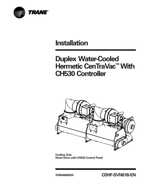
<strong>Installation</strong><br />
<strong>Duplex</strong> <strong>Water</strong>-<strong>Cooled</strong><br />
Hermetic CenTraVac With<br />
CH530 Controller<br />
Cooling Only<br />
Direct Drive with CH530 Control Panel<br />
X39640669020<br />
<strong>CDHF</strong>-<strong>SVN<strong>01</strong>B</strong>-<strong>EN</strong>
Warnings and<br />
Cautions<br />
Warnings and Cautions<br />
Notice that warnings and cautions<br />
appear at appropriate intervals<br />
throughout this manual. Warnings<br />
are provided to alert installing<br />
contractors to potential hazards that<br />
could result in personal injury or<br />
death, while cautions are designed<br />
to alert personnel to conditions that<br />
could result in equipment damage.<br />
Your personal safety and the proper<br />
operation of this machine depend<br />
upon the strict observance of these<br />
precautions.<br />
NOTICE:<br />
Warnings and Cautions appear at appropriate sections throughout this manual.<br />
Read these carefully.<br />
����� WARNING – Indicates a potentially hazardous situation which, if not avoided, could result in<br />
death or serious injury.<br />
����� CAUTION – Indicates a potentially hazardous situation which, if not avoided, may result in<br />
minor or moderate injury. It may also be used to alert against unsafe practices.<br />
CAUTION – Indicates a situation that may result in equipment or property-damage-only accidents.<br />
© 20<strong>05</strong> American Standard Inc. All rights reserved. <strong>CDHF</strong>-<strong>SVN<strong>01</strong>B</strong>-<strong>EN</strong>
<strong>CDHF</strong>-<strong>SVN<strong>01</strong>B</strong>-<strong>EN</strong><br />
Contents<br />
Warnings and Cautions<br />
General Information<br />
<strong>Water</strong> Piping<br />
Vent Line Piping<br />
Insulation<br />
Electrical Information<br />
<strong>Trane</strong> Supplied Starter<br />
Customer Supplied Starter<br />
Line Power Supply<br />
PFCC<br />
PFCC and Unit Mounted Starters<br />
Remote Starter<br />
Starter to UCP Control Wiring<br />
Control Circuit Wiring<br />
System Control Wiring<br />
Wiring Diagrams<br />
3<br />
2<br />
4<br />
25<br />
35<br />
41<br />
43<br />
44<br />
45<br />
47<br />
48<br />
50<br />
51<br />
53<br />
54<br />
56<br />
59
4<br />
General Information<br />
About this Manual<br />
Original date of manual:<br />
This manual contains information<br />
regarding installation of Models<br />
<strong>CDHF</strong> 60 Hz and CDHG 50 Hz chillers<br />
equipped with Tracer CH530<br />
controller. Reference is made to the<br />
<strong>CDHF</strong>. All installation procedures<br />
described for the <strong>CDHF</strong> apply also to<br />
the CDHG. By carefully reviewing the<br />
information in this manual and<br />
following the instructions given<br />
along with the submittal package<br />
provided for the unit will assure that<br />
the chiller is installed correctly.<br />
Product Description Block<br />
<strong>Trane</strong> 60 Hz. Model <strong>CDHF</strong> hermetic<br />
CenTraVac units are defined by the<br />
product definition and selection<br />
system (PDS). Each unit is defined by<br />
the product description block which<br />
appears on the unit nameplate. An<br />
explanation of the PDS product code<br />
is provided in the unit operation and<br />
maintenance literature.<br />
<strong>CDHF</strong>-<strong>SVN<strong>01</strong>B</strong>-<strong>EN</strong>
<strong>CDHF</strong>-<strong>SVN<strong>01</strong>B</strong>-<strong>EN</strong><br />
General Information<br />
Commonly Used Acronyms<br />
ASME = American Society of<br />
Mechanical Engineers<br />
ASHRAE = American Society of<br />
Heating, Refrigerant and Air<br />
Conditioning Engineers<br />
BAS = Building Automation System<br />
LBU = La Crosse Business Unit<br />
CABS = Auxiliary Condenser Tube-<br />
Bundle Size<br />
CDBS = Condenser Bundle Size<br />
CDSZ = Condenser Shell Size<br />
CWR = Chilled <strong>Water</strong> Reset<br />
DTFL = Delta-T at Full Load (i.e., the<br />
difference between entering and<br />
leaving chilled water temperatures at<br />
design load)<br />
EVBS = Evaporator Bundle Size<br />
EVSZ = Evaporator Shell Size<br />
GPM = Gallons-per-Minute<br />
HVAC = Heating, Ventilating, and Air<br />
Conditioning<br />
IE = Internally Enhanced Tubes<br />
IPC = Interprocessor Communication<br />
PFCC = Power Factor Correction<br />
Capacitor<br />
PSID = Pounds-per-Square-Inch<br />
(differential pressure)<br />
PSIG = Pounds-per-Square-Inch<br />
(gauge pressure)<br />
UCP = Chiller Control Panel<br />
CH530 = Tracer CH530 Chiller<br />
Controller<br />
Warnings and Cautions<br />
Notice that WARNINGS and<br />
CAUTIONS appear at appropriate<br />
intervals throughout this manual.<br />
WARNINGS are provided to alert<br />
installing contractors to potential<br />
hazards that could result in personal<br />
injury or death, while CAUTIONS are<br />
designed to alert personnel to<br />
conditions that could result in<br />
equipment damage.<br />
Your personal safety and the proper<br />
installation of this machine depend<br />
upon the strict observance of these<br />
precautions.<br />
Unit Nameplate<br />
The <strong>CDHF</strong> unit nameplate is located<br />
on the left side of the left hand unit<br />
control panel (UCP). A typical unit<br />
nameplate is illustrated in Figure 1.<br />
The following information is<br />
provided on the <strong>CDHF</strong> unit<br />
nameplate.<br />
- Unit model and size descriptor<br />
- Unit serial number<br />
- Unit electrical requirements<br />
- Correct operating charge and type<br />
of refrigerant.<br />
- Unit test pressures and maximum<br />
operating pressures<br />
- Unit <strong>Installation</strong> and Operation and<br />
Maintenance manuals<br />
- Product description block (identifies<br />
all unit components and unit<br />
“design sequence” used to order<br />
literature and make other inquiries<br />
about the unit).<br />
Metric Conversion<br />
The following conversions apply for<br />
tables and charts in this manual,<br />
In. x 2.54 = cm<br />
Ft. x 30.48 = cm.<br />
Lb. x .453 = kg.<br />
5
6<br />
General Information<br />
Figure 1 – Information from a Typical <strong>CDHF</strong> Unit Nameplate<br />
MODEL: <strong>CDHF</strong>2000 DATE OF MFG (DD/MM/YY): @TODAY<strong>05</strong><br />
MODEL NO:<br />
<strong>CDHF</strong>2000KR0TA2802745B0A106B0A1CFFRR10W4C0<strong>01</strong>03300<strong>01</strong>S<br />
SERIAL NO: S.O. NO: SAMPLE<br />
RATED VOLTAGE: 4160 VOLTS 60 HZ 3 PH<br />
VOLTAGE UTILIZATION RANGE: 3744-4576 VAC<br />
LH CIRCUIT RH CIRCUIT<br />
MINIMUM CIRCUIT AMPACITY: 96 AMPS 103 AMPS<br />
MAXIMUM OVERCURR<strong>EN</strong>T<br />
PROTECTIVE DEVICE: 150 AMPS 175 AMPS<br />
COMPRESSOR MOTOR MAX<br />
VOLTS-AC HZ PH RLA KW LRAY<br />
LH CIRCUIT 4160 60 3 75 480 400<br />
RH CIRCUIT 4160 60 3 82 523 473<br />
VOLT HZ PH<br />
OIL TANK HEATER (LH&RH): 115 60 1 750 WATTS<br />
CONTROL CIRCUIT (LH&RH): 115 60 1 4000 VA MAX<br />
CARBON TANK HEATER (LH&RH):115 60 1 1.7 RLA<br />
PUMPOUT COMPRESSOR(LH&RH): 115 60/50 1 1.55 RLA<br />
PURGE COMP MTR(LH&RH): 115/110 60/50 1 8RLA 34.6LRA<br />
WH<strong>EN</strong> MOTOR CONTROLLER PROVIDED BY OTHERS<br />
TRANE <strong>EN</strong>GINEERING SPEC. S6516-<strong>05</strong>13 APPLIES<br />
REFRIGERANT SYSTEM LH RH<br />
FIELD CHARGED WITH: 1850 1850 LBS. OF R-123<br />
ACTUALLY CHARGED WITH: LBS. OF R-123<br />
MAXIMUM WORKING PRESSURE: 15 15 PSIG HIGH SIDE<br />
MAXIMUM WORKING PRESSURE: 15 15 PSIG LOW SIDE<br />
FACTORY TEST PRESSURE:<br />
HIGH SIDE 45 PSIG LOW SIDE 45 PSIG<br />
FIELD LEAK TEST PRESSURE 8 PSIG MAX.<br />
TESTED AT PSIG<br />
MANUFACTURED UNDER ONE OR MORE OF THE FOLLOWING<br />
U.S. PAT<strong>EN</strong>TS: 4232533 4686834 4689967 4715190<br />
4751653 4800732 5031410 5<strong>05</strong>6032 5<strong>05</strong>8031 5355691<br />
5434738 5537830 5553997 5563489 5600960 5675978<br />
5836382 5848538 6065297 6098422 625<strong>01</strong><strong>01</strong><br />
SERVICE LITERATURE<br />
INSTALLATION MANUAL: <strong>CDHF</strong>-SVN<strong>01</strong>A-<strong>EN</strong><br />
OPERATION/MAINT<strong>EN</strong>ANCE MANUAL: <strong>CDHF</strong>-SVU<strong>01</strong>A-<strong>EN</strong><br />
PRODUCT DESCRIPTION:<br />
TVSQ 1 PTON 1975 VTR1 165 VTR2 165<br />
CTM1 75 CTM2 100 MAC1 6 MAC2 6<br />
MODL <strong>CDHF</strong> DSEQ R0 NTON 2000 VOLT 4160<br />
HRTZ 60 CPM1 512 CPD1 280 CPM2 588<br />
CPD2 274 EVSZ 210D EVBS 1850 EVTM TECU<br />
EVTH 35 EFLD WATE EVWT MAR EVWP 1<br />
EVWC STD EVPR 150 EVCO VICT EVWA RRLR<br />
CDSZ 210D CDBS 1900 CDTM TECU CDTH 35<br />
CFLD WATE CDWT MAR CDWP 1 CDWC STD<br />
CDPR 150 CDCO VICT CDWA LFRF ORC1 1265<br />
ORC2 1265 AGLT UL TEST CWSP TTOL SPCL<br />
WCNM BNMP CNIF CH53 OPST YES WPSR WFC<br />
TRMM TRM4 EPRO YES CDRP YES SPKG DOM<br />
ASCL OUTS APTY STD SRT1 CXL SRT2 CXL<br />
SOPT 3RTD G<strong>EN</strong>R NO<br />
<strong>CDHF</strong>-<strong>SVN<strong>01</strong>B</strong>-<strong>EN</strong>
Responsibilities of Installing<br />
Contractors<br />
For your convenience, a summary of<br />
the contractor responsibilities<br />
typically associated with the chiller<br />
installation process is provided<br />
below. Table 1 further categorizes<br />
these responsibilities by<br />
differentiating between <strong>Trane</strong>supplied<br />
and field-supplied and field<br />
installed components.<br />
Refer to the <strong>Installation</strong> section of<br />
this manual for more detailed<br />
instructions.<br />
Locate and maintain the loose<br />
parts, i.e. isolators, bulb wells,<br />
temperature sensors, flow sensors<br />
or other factory-ordered field<br />
installed options, for installation as<br />
required. Loose parts are located in<br />
the starter panel on units with<br />
factory-installed unit-mounted<br />
starters or in the motor terminal<br />
box for units with remote-mounted<br />
starters.<br />
Install unit on a foundation with flat<br />
support surfaces level within 1/16”,<br />
and of sufficient strength to<br />
support concentrated loading.<br />
Place manufacturer-supplied<br />
isolation pad assemblies under<br />
unit. (Use spring isolators for upper<br />
floor installations).<br />
Install unit per applicable <strong>Trane</strong><br />
installation manual.<br />
Complete all water piping and<br />
electrical connections.<br />
<strong>CDHF</strong>-<strong>SVN<strong>01</strong>B</strong>-<strong>EN</strong><br />
General Information<br />
Note: Field-piping must be arranged<br />
and supported to avoid stress on the<br />
equipment. It is strongly<br />
recommended that the piping<br />
contractor refrain from piping closer<br />
than 3’-0” minimum to the<br />
equipment. This will allow for proper<br />
fit-up upon arrival of the unit at the<br />
jobsite. Any adjustment that is<br />
necessary can be made to the piping<br />
at that time.<br />
Where specified, supply and install<br />
valves in water piping upstream<br />
and downstream of evaporator and<br />
condenser water boxes to isolate<br />
shells for maintenance, and to<br />
balance/trim system.<br />
Supply and install flow switches (or<br />
equivalent devices) in both chilled<br />
water and condenser water piping.<br />
Interlock each switch with proper<br />
pump starter to ensure unit can<br />
only operate when water flow is<br />
established.<br />
Supply and install taps for<br />
thermometers and pressure<br />
gauges in water piping adjacent to<br />
inlet and outlet connections of both<br />
evaporator and condenser.<br />
Supply and install drain valves on<br />
each water box.<br />
Supply and install vent cocks on<br />
each water box.<br />
Where specified, supply and install<br />
strainers ahead of all pumps and<br />
automatic modulating valves.<br />
Supply and install pressure relief<br />
piping from pressure-relief rupture<br />
disc to atmosphere.<br />
If necessary, supply sufficient<br />
Refrigerant-HCFC-22 (maximum of<br />
1 lb. per machine) and dry nitrogen<br />
(8 psig per machine) for pressure<br />
testing under manufacturer’s<br />
supervision.<br />
Start unit under supervision of a<br />
qualified service technician.<br />
Where specified, supply and<br />
insulate evaporator and any other<br />
portions of machine as required to<br />
prevent sweating under normal<br />
operating conditions.<br />
Unit-Mounted Starters Only,<br />
remove top of starter panel and cut<br />
access area for line-side wiring;<br />
front left quadrant of top provides<br />
recommended access to starter<br />
lugs.<br />
Supply and install wire terminal<br />
lugs to starter.<br />
Unit-Mounted Starters Only,<br />
Supply and install field wiring to<br />
line-side lugs of starter.<br />
Supply and install a Refrigerant<br />
Monitor per ASHRAE 15<br />
specifications. Reference the<br />
compliance to ASHRAE Standard<br />
15 as shown on the “Model<br />
CenTraVac Checksheet and<br />
Request for Serviceman”.<br />
To obtain a copy of “Model<br />
CenTraVac Checksheet and Request<br />
for Serviceman” (Form 1-27.08-6)<br />
order from your local <strong>Trane</strong> office.<br />
7
8<br />
General Information<br />
Table 1 – <strong>Installation</strong> Requirements<br />
Type of <strong>Trane</strong>-Supplied <strong>Trane</strong>-Supplied Field-Supplied<br />
Requirement <strong>Trane</strong>-Installed Field-Installed Field-Installed<br />
Rigging A. Safety chains<br />
B. Clevis connectors<br />
C. Lifting beam<br />
Isolation A. Isolation pads or A. Isolation pads or spring isolators<br />
spring isolators<br />
Electrical A. Circuit breakers or A. Jumper bars A. Circuit breakers or fusible<br />
fusible disconnects B. Temperature sensor disconnects (optional)<br />
(optional) (optional outdoor air) B. Remote-mounted starter<br />
B. Unit-mounted C. Flow switches (may C. PFCCs (Remote-mounted<br />
starter (optional) be field supplied) starter option only)<br />
C. PFCCs (optional) D. Terminal lugs<br />
E. Ground connection(s)<br />
F. Jumper bars<br />
G. BAS wiring (optional)<br />
H. IPC wiring (remotemounted<br />
starters only<br />
I. Control voltage wiring<br />
(remote-mounted starters only)<br />
J. Oil pump interlock wiring<br />
(remote-mounted<br />
starters only)<br />
K. High condenser pressure<br />
interlock wiring<br />
(remote-mounted starters only).<br />
L. Chilled water pump contactor<br />
and wiring<br />
M.Condenser water pump<br />
contactor and wiring<br />
N. Option relays and wiring<br />
(See Table 14 & 16)<br />
<strong>Water</strong> Piping A. Flow switches (May A. Thermometers<br />
be field supplied) B. <strong>Water</strong> flow pressure gauges<br />
C. Isolation and balancing valves<br />
water piping<br />
D. Vents and drain valves<br />
(1 each per class)<br />
E. Pressure-relief valves<br />
(for water boxes as required)<br />
Rupture Disc A. Rupture disc assy A. Vent line and flexible connector<br />
Insulation A. Insulation (Optional) A. Insulation<br />
<strong>CDHF</strong>-<strong>SVN<strong>01</strong>B</strong>-<strong>EN</strong>
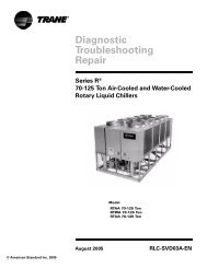
Unit Shipment<br />
Each chiller ships from the factory as<br />
a hermetically assembled package; it<br />
is factory piped, wired and tested. All<br />
openings are covered or plugged to<br />
prevent contamination during<br />
shipment and handling.<br />
See Figure 2 for an illustration of a<br />
typical unit and its components. As<br />
soon as the unit arrives at the job<br />
site, inspect it thoroughly for<br />
damage and material shortages. In<br />
addition:<br />
1. Verify the chiller’s hermetic<br />
integrity by checking the<br />
evaporator pressure for an<br />
indication of holding charge<br />
pressure.<br />
Note: Since there are two refrigerant<br />
circuits both must be checked.<br />
<strong>CDHF</strong>-<strong>SVN<strong>01</strong>B</strong>-<strong>EN</strong><br />
General Information<br />
To prevent damaging moisture from<br />
entering the unit and causing<br />
corrosion, each chiller is pressurized<br />
with dry nitrogen before shipment.<br />
Note: The holding charge should<br />
register approximately 5 psig (at sea<br />
level) on the gauge. If the charge has<br />
escaped, contact your local <strong>Trane</strong><br />
sales office for instructions.<br />
2. Check the oil sump sight glasses<br />
to verify that the sump was<br />
factory-charged with 9 gallons of<br />
oil. If no oil level is visible, contact<br />
your local <strong>Trane</strong> sales office.<br />
3. Compare the unit nameplate data<br />
(including electrical characteristics)<br />
with the corresponding ordering<br />
and shipping information to verify<br />
that the correct unit was shipped<br />
to the job site.<br />
If a thorough inspection of the<br />
chiller reveals damage or material<br />
shortages, be sure to file these<br />
claims with the carrier<br />
immediately. Specify the extent<br />
and type of damage found, and<br />
notify the appropriate <strong>Trane</strong> sales<br />
representative. Do not install a<br />
damaged unit without the sales<br />
representative’s approval!<br />
Storage<br />
If the chiller will be stored at the job<br />
site for an extended period of time<br />
before it is installed, exercise these<br />
precautionary measures to protect<br />
the unit from damage:<br />
1. Do not remove the protective<br />
coverings factory-installed on the<br />
control panel and compressor<br />
inlet vane actuator for shipment.<br />
2. Store the chiller in a dry vibration<br />
free and secure area. If factory<br />
insulated, protect chiller from<br />
prolonged exposure to sunlight.<br />
CAUTION<br />
Insulation Damage!<br />
To prevent damage to the factoryinstalled<br />
insulation, do not allow<br />
excessive exposure to sunlight.<br />
3. Periodically check the condenser<br />
and evaporator pressure to verify<br />
that the 5 psig dry nitrogen at 72°F<br />
ambient holding charge is still in<br />
the chiller. If this charge escapes,<br />
contact a qualified service<br />
organization and the <strong>Trane</strong> sales<br />
engineer that handled the order.<br />
Note: The storage range for the<br />
microcomputer-based devices in the<br />
unit control panel is -40°F to 158°F<br />
(-40°C to 70°C).<br />
9
Figure 2 – Typical <strong>CDHF</strong> Chiller<br />
10<br />
General Information<br />
<strong>CDHF</strong>-<strong>SVN<strong>01</strong>B</strong>-<strong>EN</strong>
<strong>CDHF</strong>-<strong>SVN<strong>01</strong>B</strong>-<strong>EN</strong><br />
General Information<br />
Recommended Unit<br />
Clearances<br />
Adequate clearance around and<br />
above the chiller is required to allow<br />
sufficient access for service and<br />
maintenance operations.<br />
Figure 3 illustrates the<br />
recommended clearances for units<br />
with and without options. Figure 4<br />
shows tube bundle locations. Notice<br />
that, in each instance, the minimum<br />
vertical clearance above the chiller is<br />
3-feet.<br />
In addition, be sure to provide at<br />
least 3-feet of working space in front<br />
of the unit control panel to satisfy the<br />
National Electrical Code, and/or local<br />
codes.<br />
Important! Do not install piping or<br />
conduit above the compressor<br />
motor assembly or behind the<br />
suction elbow!<br />
Note: Specific unit clearance<br />
requirements are also indicated in<br />
the submittal package provided for<br />
your unit.<br />
Operating Environment<br />
Besides assuring that the site<br />
selected for chiller installation<br />
provides the necessary clearances,<br />
consider the equipment’s operating<br />
environment.<br />
To assure that electrical components<br />
operate properly, do not locate the<br />
chiller in an area exposed to dust,<br />
dirt, corrosive fumes, or excessive<br />
heat and humidity. Note that the<br />
maximum ambient temperature for<br />
chiller operation is 95 to 100°F (35° -<br />
38° C).<br />
CAUTION<br />
Equipment Failure!<br />
<strong>CDHF</strong> operation at ambient<br />
temperatures exceeding 100°F<br />
(38°C) can fatigue the unit’s rupture<br />
disc, causing it to break at a reduced<br />
refrigerant pressure (i.e.,
Figure 3 – Clearance Requirements for Standard <strong>CDHF</strong><br />
12<br />
General Information<br />
Notes:<br />
1. Per NEC Article 110 - Unit mounted starters from 0-600V require 42" clearance; 6<strong>01</strong>-2500V require 48" clearance;<br />
25<strong>01</strong>-9000V require 60" clearance.<br />
2. Clearance 1 can be at either end of machine and is required for tube pull clearance<br />
Clearance 2 is always at the opposite end of machine from Clearance1 and is required for service clearance<br />
3. Clearance requirement for evaporator tube removal does not include water box. Add water box dimension to this<br />
figure.<br />
UCP Clearance Requirements for Standard <strong>CDHF</strong><br />
CL1 CL2<br />
Shell Width Entire Width Height Length Entire Length Clearance 1 Clearance 2<br />
210 D 130.875 184.875 132.750 258.000 606.000 264.000 84.000<br />
250 D 142.625 196.625 136.875 258.000 606.000 264.000 84.000<br />
250 M 142.625 196.625 141.375 312.000 714.000 318.000 84.000<br />
250 X 142.625 196.625 141.375 360.000 810.000 366.000 84.000<br />
<strong>CDHF</strong>-<strong>SVN<strong>01</strong>B</strong>-<strong>EN</strong>
Figure 4 – Tube Bundle Locations for Model <strong>CDHF</strong> Units<br />
<strong>CDHF</strong>-<strong>SVN<strong>01</strong>B</strong>-<strong>EN</strong><br />
General Information<br />
Cooling Only and Free Cooling Units<br />
EVSZ CDSZ A B C D E F G H<br />
210 D 210 D 4’-5-7/16" 5"-3/8" 7’-9/16" 1’-4-1/4" 5’-0-1/8" 3’-5-1/4" 2’-5" 3’-10-3/16"<br />
250 D 250 D 5’-0-3/4" 5"-1/4 6"-1/2 1’-7-1/4" 5’-8-3/4" 3’-10-5/8" 2’-4-1/8" 3’-11-5/8"<br />
250 M 250 M 5’-0-3/4" 5"-1/4 6"-1/2 1’-7-1/4" 5’-8-3/4" 3’-10-5/8" 2’-4-1/8" 3’-11-5/8"<br />
250 X 250 X 5’-0-3/4" 5"-1/4 6"-1/2 1’-7-1/4" 5’-8-3/4" 3’-10-5/8" 2’-4-1/8" 3’-11-5/8"<br />
13
14<br />
General Information<br />
Table 2 – Typical Shipping and Operating Weights<br />
Operating Weight Shipping Weight<br />
TYPE NTON CPKW EVSZ CDSZ (lbs) (kg) (lbs) (kg)<br />
<strong>CDHF</strong> 1500-2000 957 210D 210D 8<strong>01</strong>71 36366 68629 31130<br />
<strong>CDHF</strong> 2100-2500 1228 250D 250D 93186 42269 79213 35931<br />
CDHG 1250-1750 716 210D 210D 82349 37354 70807 32118<br />
CDHG 2150 892 210D 210D 89680 197710 78288 172595<br />
CDHG 2150 892 250D 250D 96964 43983 82991 37645<br />
<strong>CDHF</strong> 3000 1340 250M 250M 106659 48381 89425 4<strong>05</strong>63<br />
<strong>CDHF</strong><br />
Notes:<br />
3500 1340 250X 250X 114445 51912 95077 43127<br />
Weights shown above are accurate within +/- 3% and are based on the following<br />
Operating weights include refrigerant, oil charge and water<br />
Shells are with largest bundles and TECU .028 wall tubes<br />
Compressor weight with medium voltage motor and above CPKW<br />
Starter weights not included<br />
<strong>Water</strong>boxes are 1 pass, 150 psig Non-Marine<br />
For other configurations refer to submittal package<br />
<strong>CDHF</strong>-<strong>SVN<strong>01</strong>B</strong>-<strong>EN</strong>
Note: Immediately report any unit<br />
damage incurred during handling or<br />
installation at the job site to the<br />
<strong>Trane</strong> sales office.<br />
Rigging<br />
Lifting is the recommended method<br />
for moving chillers. Suggested lifting<br />
arrangements for standard units are<br />
illustrated in Figure 5.<br />
Note that each of the cables used to<br />
lift the unit must be capable of<br />
supporting the entire weight of the<br />
chiller. (See Table 2 for unit shipping<br />
and operating weights.) Notice that<br />
the lifting beam used to lift the unit<br />
must be at least 23 feet long.<br />
See Figure 5 and Table 2 for<br />
guidance in selecting cable or sling<br />
lengths.<br />
� WARNING<br />
Test Lift!<br />
Verify chiller remains horizontal.<br />
To avoid serious injury and possible<br />
equipment damage, lift the chiller<br />
horizontally; use the lifting<br />
arrangement and rigging shown in<br />
Figure 5. Failure to lift unit as<br />
recommended could result in death<br />
or serious injury or lead to<br />
equipment damage.<br />
<strong>CDHF</strong>-<strong>SVN<strong>01</strong>B</strong>-<strong>EN</strong><br />
General Information<br />
To lift the chiller properly, insert<br />
clevis connections at the points<br />
indicated in Figure 5; a 2-1/2”<br />
diameter lifting hole is provided at<br />
each of these points. Next, attach the<br />
lifting cables or slings.<br />
Once the lifting cables are in place,<br />
attach a safety cable or sling<br />
between the first-stage casting of the<br />
compressor and the lifting beam. To<br />
do this, remove a retaining bolt from<br />
the compressor first-stage casting<br />
and replace it with an eyebolt, or<br />
swivel clevis.<br />
Note: There should not be tension<br />
on this safety cable; it is used only to<br />
prevent the unit from rolling during<br />
the lift.<br />
When the lift is completed, detach<br />
the clevis connections and safety<br />
chain, then remove the eyebolt that<br />
was used to secure the safety chain<br />
to the compressor, and reinstall the<br />
retaining bolt in its place. If the chiller<br />
cannot be moved using the<br />
conventional rigging method just<br />
described, consider these points.<br />
1. If job site conditions require<br />
rigging of the chiller at an angle<br />
greater than 45° from horizontal<br />
(end-to-end), dowel-pin the compressor<br />
and remove it from the<br />
unit. Be sure to contact a qualified<br />
service organization for specific<br />
rigging instructions.<br />
CAUTION<br />
Oil Loss!<br />
To prevent oil migration out of the<br />
oil tank during lifting procedures,<br />
remove the oil from the oil tank if<br />
the unit will be lifted at any angle<br />
greater than 15° from horizontal<br />
end-to-end. If oil is allowed to run<br />
out of the oil tank into other areas of<br />
the chiller, it will be extremely<br />
difficult to return the oil to the oil<br />
tank even during operation.<br />
2. When lifting the chiller is either<br />
impractical or undesirable, attach<br />
cables or chains to the jacking<br />
slots shown in Figure 5; then push<br />
or pull the unit across a smooth<br />
surface. Should the chiller be on a<br />
shipping skid, it is not necessary to<br />
remove the shipping skid from the<br />
chiller before moving it into place.<br />
CAUTION<br />
Equipment Damage!<br />
To prevent possible equipment<br />
damage, do not use a fork lift to<br />
move the chiller!<br />
CAUTION<br />
Compressor Alignment!<br />
Lifting the compressor/motor<br />
assembly from the shells without<br />
factory-installed doweling in the<br />
compressor casting flanges may<br />
result in misalignment of the<br />
compressor castings.<br />
3. Position isolator pads (or spring<br />
isolators) beneath the chiller feet;<br />
see “Unit Isolation” section for<br />
instructions.<br />
4. Once the isolators are in place,<br />
lower the chiller; again, work from<br />
end to end in small increments to<br />
maintain stability.<br />
15
Figure 5 – Recommended Lifting Arrangements for <strong>CDHF</strong><br />
16<br />
B<br />
A<br />
Jacking Points<br />
C<br />
Safety Chain<br />
General Information<br />
H<br />
TYPE NTON EVSZ CDSZ X Y H<br />
<strong>CDHF</strong> 1500-2000 210D 210D 143 in. 23 ft 24.75 in<br />
<strong>CDHF</strong> 2100-2500 250D 250D 143 in. 23 ft 24.75 in<br />
CDHG 1250-1750 210D 210D 143 in. 23 ft 24.75 in<br />
CDHG 2150 210D 210D 143 in. 23 ft 24.75 in<br />
CDHG 2150 250D 250D 143 in. 23 ft 24.75 in<br />
<strong>CDHF</strong> 3000 250M 250M 172 in. 27.5 ft 24.75 in<br />
<strong>CDHF</strong><br />
Notes:<br />
3500 250X 250X 199 in. 31.5 ft 24.75 in<br />
1. Lifting chains (or cables) are not the same length between point A and B, or between points A and C. Adjust as<br />
necessary for an even lift.<br />
2. Lifting holes provided on chillers to attach chains are 2 1/2 inch in diameter.<br />
3. Attach safety chain (or cable) as shown, and without tension. The safety chain is not used for lifting, but is there to<br />
prevent the unit from rolling.<br />
4. Do not fork-lift the unit.<br />
X<br />
Y<br />
Safety<br />
Chain<br />
LIFTING BEAM<br />
<strong>CDHF</strong>-<strong>SVN<strong>01</strong>B</strong>-<strong>EN</strong>
Unit Isolation<br />
To minimize sound and vibration<br />
transmission through the building<br />
structure - and to assure proper<br />
weight distribution over the<br />
mounting surface, always install<br />
isolation pads or spring isolators<br />
under the chiller feet.<br />
Note: Isolation pads (Figure 6) are<br />
provided with each chiller unless<br />
spring isolators are specified on the<br />
sales order.<br />
Note: The center support is<br />
approximately 1/2" shorter (higher)<br />
than the end supports. After unit<br />
leveling, shim the center isolator<br />
pads. If spring isolators are used,<br />
shim the isolators for the center<br />
support. See Figure 7.<br />
Specific isolator loading data is<br />
provided in the unit submittal<br />
package. If necessary, contact your<br />
local <strong>Trane</strong> sales office for further<br />
information.<br />
Important! When determining<br />
placement of isolation pads or spring<br />
isolators, remember that the control<br />
panel side of the unit is always<br />
designated as the unit front.<br />
<strong>CDHF</strong>-<strong>SVN<strong>01</strong>B</strong>-<strong>EN</strong><br />
5/16-3/8"<br />
[8-10 mm]<br />
General Information<br />
Isolation Pads<br />
When the unit is ready for final<br />
placement, position isolation pads<br />
under the chiller feet as shown in<br />
Figure 7.<br />
Remember that the chiller must be<br />
level within 1/16” over its length and<br />
width after it is lowered onto the<br />
isolation pads. In addition, all piping<br />
connected to the chiller must be<br />
properly isolated and supported so<br />
that it does not place any stress on<br />
the unit.<br />
Spring Isolators<br />
Spring isolators should be<br />
considered whenever chiller<br />
installation is planned for an upper<br />
story location. Base isolator selection<br />
and placement on the information<br />
presented in Figures 8-10a. (Notice<br />
that 3 types of spring isolators - each<br />
with its own maximum loading<br />
characteristics are used with <strong>CDHF</strong><br />
chillers).<br />
Spring isolators typically ship<br />
assembled and ready for installation.<br />
To install and adjust the isolators<br />
properly, follow the instructions<br />
given.<br />
Figure 6 – Isolation Pad<br />
Note: Do not adjust the isolators<br />
until the chiller is piped and charged<br />
with refrigerant and water.<br />
1. Position the spring isolators under<br />
the chiller as shown in Figures 8<br />
and 9. Make sure that each isolator<br />
is centered in relation to the tube<br />
sheet.<br />
Note: Spring isolators shipped with<br />
the chiller are not identical! Be sure<br />
to compare the data provided in the<br />
unit submittal package and Figures 8<br />
through 10a to determine proper<br />
isolator placement.<br />
2. Set the isolators on the sub-base;<br />
shim as necessary to provide a<br />
flat, level surface at the same<br />
elevation for the end supports,<br />
and approximately 1/2" higher for<br />
the center support. Be sure to<br />
support the full underside of the<br />
isolator base plate; do not straddle<br />
gaps or small shims.<br />
18"<br />
[457 mm]<br />
6"<br />
[152.4 mm]<br />
17
Figure 7 – Isolation Pad Placement - <strong>CDHF</strong>, CDHG<br />
18<br />
General Information<br />
Important:<br />
Center support is 1/2" (13mm) shorter than end supports. Requires 1/2" steel shim under pad for Center<br />
Support at installation after leveling.<br />
Isolation Pad Loading (lb)<br />
TYPE NTON CPKW EVSZ CDSZ Left Pad Center Pad Right Pad<br />
<strong>CDHF</strong> 1500-2000 957 210D 210D 25150 26718 28304<br />
<strong>CDHF</strong> 2100-2500 1228 250D 250D 29292 31<strong>05</strong>6 32838<br />
CDHG 1250-1750 716 210D 210D 25997 27446 28907<br />
CDHG 2150 892 210D 210D 26507 29850 33322<br />
CDHG 2150 892 250D 250D 20680 32316 33967<br />
<strong>CDHF</strong> 3000 1340 250M 250M 33527 35546 37586<br />
<strong>CDHF</strong> 3500 1340 250X 250X 35975 38140 40330<br />
Isolation Pad Loading (kg)<br />
TYPE NTON CPKW EVSZ CDSZ Left Pad Center Pad Right Pad<br />
<strong>CDHF</strong> 1500-2000 957 210D 210D 11408 12119 12839<br />
<strong>CDHF</strong> 2100-2500 1228 250D 250D 13287 14087 14895<br />
CDHG 1250-1750 716 210D 210D 11792 12449 13112<br />
CDHG 2150 892 210D 210D 58438 65808 73462<br />
CDHG 2150 892 250D 250D 13916 14659 15407<br />
<strong>CDHF</strong> 3000 1340 250M 250M 15208 16123 17049<br />
<strong>CDHF</strong> 3500 1340 250X 250X 16318 17300 18294<br />
Notes:<br />
Isolator pad loading is based on the following<br />
Operating weights include refrigerant, oil charge and water<br />
Shells are with largest bundles and TECU .028 wall tubes<br />
Compressor weight with medium voltage motor and above CPKW<br />
Starter weights not included<br />
<strong>Water</strong>boxes are 1 pass, 150 psig Non-Marine<br />
For other configurations refer to submittal package<br />
<strong>CDHF</strong>-<strong>SVN<strong>01</strong>B</strong>-<strong>EN</strong>
Figure 8 – Spring Isolator Placement - <strong>CDHF</strong>, CDHG<br />
<strong>CDHF</strong>-<strong>SVN<strong>01</strong>B</strong>-<strong>EN</strong><br />
General Information<br />
Estimated Spring Isolator Loading (lb)<br />
TYPE NTON CPKW EVSZ CDSZ LF MF RF LR MR RR<br />
<strong>CDHF</strong> 1500-2000 957 210D 210D 14120 14948 15785 11029 11770 12519<br />
<strong>CDHF</strong> 2100-2500 1228 250D 250D 13861 14721 15591 15431 16334 17247<br />
CDHG 1250-1750 716 210D 210D 14432 15193 15960 11564 12253 12947<br />
CDHG 2150 892 210D 210D 15623 17428 19299 10884 12422 14023<br />
CDHG 2150 892 250D 250D 14413 15209 16<strong>01</strong>2 16267 17108 17955<br />
<strong>CDHF</strong> 3000 1340 250M 250M 15865 16850 17845 17663 18696 19741<br />
<strong>CDHF</strong> 3500 1340 250X 250X 17023 18080 19148 18952 20060 21182<br />
Estimated Spring Isolator Loading (kg)<br />
TYPE NTON CPKW EVSZ CDSZ LF MF RF LR MR RR<br />
<strong>CDHF</strong> 1500-2000 957 210D 210D 64<strong>05</strong> 6780 7160 5003 5339 5679<br />
<strong>CDHF</strong> 2100-2500 1228 250D 250D 6287 6678 7072 7000 7409 7823<br />
CDHG 1250-1750 716 210D 210D 6546 6892 7239 5246 5558 5873<br />
CDHG 2150 892 210D 210D 34443 38422 42547 23995 27386 30915<br />
CDHG 2150 892 250D 250D 6538 6899 7263 7379 7760 8145<br />
<strong>CDHF</strong> 3000 1340 250M 250M 7196 7643 8095 8<strong>01</strong>2 8480 8954<br />
<strong>CDHF</strong> 3500 1340 250X 250X 7722 82<strong>01</strong> 8686 8597 9099 9608<br />
Notes:<br />
Vibration isolator loading is based on the following<br />
Operating weights include refrigerant, oil charge and water<br />
Shells are with largest bundles and TECU .028 wall tubes<br />
Compressor weight with medium voltage motor and above CPKW<br />
Starter weights not included<br />
<strong>Water</strong>boxes are 1 pass, 150 psig Non-Marine<br />
For other configurations refer to submittal package<br />
19
Figure 9 – Chiller Foot/Isolator Orientation<br />
20<br />
Center tube sheet<br />
support leg<br />
General Information<br />
Side View of Unit End View of Unit<br />
Center of<br />
Isolator Spring<br />
Note: The spring isolator must be centered in relation<br />
to the tube sheet. Do not align the isolator with the<br />
flat part of the chiller foot, because the tube sheet is<br />
often off-center.<br />
3. If required, bolt the isolators to the<br />
floor through the slots provided,<br />
or cement the pads.<br />
Note: Fastening the isolators to the<br />
floor is not necessary unless<br />
specified.<br />
4. If the chiller must be fastened to<br />
the isolators, insert capscrews<br />
through the chiller base and into<br />
the holes tapped in the upper<br />
housing of each isolator. However,<br />
do not allow the screws to<br />
protrude below the underside of<br />
the isolator upper housing. An<br />
alternative method of fastening<br />
the chiller to the isolators is to<br />
cement the neoprene pads.<br />
Outside edge of<br />
tube sheet<br />
5. Set the chiller on the isolators;<br />
refer to “Rigging” for lifting<br />
instructions.<br />
The weight of the chiller will force<br />
the upper housing of each isolator<br />
down, perhaps causing it to rest<br />
on the isolator’s lower housing.<br />
(Figure 10, 10a illustrates spring<br />
isolator construction.)<br />
6. Check the clearance (labeled X in<br />
Figure 10, 10a ) on each isolator. If<br />
this dimension is less than 1/4” on<br />
any isolator, use a wrench to turn<br />
the adjusting bolt one complete<br />
revolution upward.<br />
Note: When the load is applied to<br />
the isolators (Step 5), the top plate<br />
of each isolator moves down to<br />
compress the springs until either:<br />
a. The springs support the load; or<br />
b. The top plate rests on the<br />
bottom housing of the isolator.<br />
1. If the springs are supporting<br />
the load, screwing down on<br />
the adjusting bolt (Step 7) will<br />
immediately begin to raise<br />
the chiller.<br />
End of tube<br />
sheet<br />
Note: Place isolator near outside<br />
edge of tube sheet as shown.<br />
7. Turn the adjusting bolt on each of<br />
the remaining isolators to obtain<br />
the required minimum clearance<br />
at X (Figure 10, 10a ) of 1/4”.<br />
8. Once the minimum required<br />
clearance is obtained on each of<br />
the isolators, level the chiller by<br />
turning the adjusting bolt on each<br />
of the isolators on the low side of<br />
the unit. Be sure to work from one<br />
isolator to the next. Remember<br />
that the chiller must be level to<br />
within 1/16”: over its length and<br />
width, and that clearance X of<br />
each isolator must be at least 1/4<br />
inch.<br />
<strong>CDHF</strong>-<strong>SVN<strong>01</strong>B</strong>-<strong>EN</strong>
Figure 10 – Typical Spring Isolator Types and Construction<br />
Type CT-4 Spring Isolators<br />
5/8" [16 mm]<br />
9-1/4"<br />
[235 mm]<br />
C-C<br />
foundation<br />
bolts<br />
6-1/2" [165 mm]<br />
Free Height<br />
Type CT-7 Spring Isolators<br />
8-3/4" [222<br />
mm] C-C<br />
foundation<br />
bolts<br />
6-5/8" [168<br />
mm] Free<br />
Height<br />
5/8"<br />
[16 mm]<br />
<strong>CDHF</strong>-<strong>SVN<strong>01</strong>B</strong>-<strong>EN</strong><br />
5/8"<br />
[16 mm]<br />
7-1/2" [191 mm]<br />
10-1/4"<br />
[260 mm]<br />
Adjusting Bolt<br />
7-1/4"<br />
[184 mm]<br />
9-3/4"<br />
[248 mm]<br />
General Information<br />
Adjust the isolator so<br />
that the upper<br />
housing clears the<br />
lower housing by at<br />
least 1/4” [6 mm]<br />
Acoustical nonskid<br />
neoprene pad (top<br />
and bottom)<br />
Adjust the isolator so that<br />
the upper housing clears the<br />
lower housing by at least<br />
1/4” [6 mm]<br />
Adjusting Bolt<br />
Acoustical nonskid<br />
neoprene pad (top<br />
and bottom)<br />
Isolator Maximum Spring<br />
Type Load Deflection Color<br />
and Size (lbs.) (Inches) Coding<br />
CT-4-25 1,800 1.22 Red<br />
CT-4-26 2,400 1.17 Purple<br />
CT-4-27 3,000 1.06 Orange<br />
CT-4-28 3,600 1.02 Green<br />
CT-4-31 4,400 0.83 Gray<br />
CT-4-32 5,200 0.74 White<br />
Isolator Maximum Spring<br />
Type Load Deflection Color<br />
and Size (Kg) (mm) Coding<br />
CT-4-25 816 31 Red<br />
CT-4-26 1,089 30 Purple<br />
CT-4-27 1,361 27 Orange<br />
CT-4-28 1,633 26 Green<br />
CT-4-31 1,996 21 Gray<br />
CT-4-32 2,359 19 White<br />
Isolator Maximum Spring<br />
Type Load Deflection Color<br />
and Size (lbs.) (Inches) Coding<br />
CT-7-25 3,150 1.22 Red<br />
CT-7-26 4,200 1.17 Purple<br />
CT-7-27 5,250 1.06 Orange<br />
CT-7-28 6,300 1.02 Green<br />
CT-7-31 7,700 0.83 Gray<br />
CT-7-32 9,100 0.74 White<br />
Isolator Maximum Spring<br />
Type Load Deflection Color<br />
and Size (Kg) (mm) Coding<br />
CT-7-25 1,429 31 Red<br />
CT-7-26 1,9<strong>05</strong> 30 Purple<br />
CT7-27 2,381 27 Orange<br />
CT-7-28 2,858 26 Green<br />
CT-7-31 3,493 21 Gray<br />
CT-7-32 4,128 19 White<br />
21
Figure 10A – Typical Spring Isolator Types and Construction<br />
CT-12 Spring Isolators<br />
3-1/2"<br />
[89 mm]<br />
7"<br />
[178<br />
mm]<br />
8-1/8" [206<br />
mm] Free<br />
Height<br />
22<br />
5/8"<br />
[16 mm]<br />
5/8"<br />
[16 mm]<br />
12-1/2"<br />
[318 mm]<br />
(2) Adjusting Bolts<br />
General Information<br />
14-3/4" [375 mm]<br />
7-3/8" [187 mm]<br />
6-1/2"<br />
[165 mm]<br />
6-5/8"<br />
[168 mm]<br />
13-1/4" [337 mm]<br />
Adjust the isolator so that<br />
the upper housing clears the<br />
lower housing by at least<br />
1/4” [6.4 mm]<br />
Acoustical nonskid<br />
neoprene pad (top<br />
and bottom)<br />
Isolator Max Deflection Spring<br />
Type/Size Load lb (kg) inches (mm) Color Code<br />
CT-12-25 5,400 1.22 Red<br />
CT-12-26 7,200 1.17 Purple<br />
CT-12-27 9,000 1.06 Orange<br />
CT-12-28 10,800 1.02 Green<br />
CT-12-31 13,200 0.83 Gray<br />
CT-12-32 15,600 0.74 White<br />
<strong>CDHF</strong>-<strong>SVN<strong>01</strong>B</strong>-<strong>EN</strong>
CT-16 and CT20<br />
Spring Isolators<br />
<strong>CDHF</strong>-<strong>SVN<strong>01</strong>B</strong>-<strong>EN</strong><br />
General Information<br />
Isolator Max Deflection Spring<br />
Type/Size Load lb (kg) inches (mm) Color Code<br />
CT 16-26 9600 (4355) 1.17 (29.7) Purple<br />
CT 16-27 12000 (5443) 1.06 (26.9) Orange<br />
CT 16-28 14400 (6532) 1.02 (25.9) Green<br />
CT 16-31 17600 (7983) 0.83 (21.1) Gray<br />
CT 16-32 20800 (9435) 0.74 (18.8) White<br />
Isolator Max Deflection Spring<br />
Type/Size Load lb (kg) inches (mm) Color Code<br />
CT 20-26 12000 (5443) 1.17 (29.7) Purple<br />
CT 20-27 15000 (6804) 1.06 (26.9) Orange<br />
CT 20-28 18000 (8165) 1.02 (25.9) Green<br />
CT 20-31 22000 (9979) 0.83 (21.1) Gray<br />
CT 20-32 26000 (11794) 0.74 (18.8) White<br />
23
24<br />
General Information<br />
Unit Leveling<br />
Follow the instructions outlined<br />
below and illustrated in Figure 11 to<br />
determined whether or not the<br />
chiller is set level.<br />
1. Measure an equal distance up<br />
from each foot of the chiller<br />
(identified as X in Figure 11) and<br />
make a punch mark at each<br />
measured distance.<br />
2. Suspend a clear plastic tube along<br />
the length of the chiller as shown<br />
in Figure 11.<br />
Figure 11 – Checking Unit Levelness<br />
Raise chiller at one<br />
end to align match<br />
marks with water<br />
level.<br />
Clear Plastic Tube<br />
(Fill tube with water to punch mark.)<br />
3. Fill the tube with water until the<br />
level aligns with the punch mark at<br />
one end of the chiller; then check<br />
the water level at the opposite<br />
mark.<br />
If the water level does not align<br />
with the punch mark, use fulllength<br />
shims to raise one end of<br />
the chiller until the water level at<br />
each end of the tube aligns with<br />
the punch marks at both ends of<br />
the chiller<br />
4. Once the unit is level across its<br />
length, repeat Steps 1 through 3 to<br />
see if unit is level across the width.<br />
5. If isolation pads have been used,<br />
shim the center support.<br />
Measure and mark<br />
an equal distance<br />
up from each<br />
chiller foot.<br />
<strong>CDHF</strong>-<strong>SVN<strong>01</strong>B</strong>-<strong>EN</strong>
Overview<br />
Several water piping circuits must be<br />
installed and connected to the chiller.<br />
Note: Field piping must be arranged<br />
and supported to avoid stress on the<br />
equipment. It is strongly<br />
recommended that the piping<br />
contractor refrain from piping closer<br />
than 3’-0” minimum to the<br />
equipment. This will allow for proper<br />
fit-up upon arrival of the unit at the<br />
job-site. Any adjustment that is<br />
necessary can be made to the piping<br />
at that time.<br />
1. Pipe the evaporator into the chilled<br />
water circuit.<br />
2. Pipe the condenser into the<br />
cooling tower water circuit. Piping<br />
suggestions for each of the water<br />
circuits listed above are outlined<br />
later in this section. General<br />
recommendations for the<br />
installation of field-supplied piping<br />
components (e.g., valves, flow<br />
switches, etc.) common to most<br />
chiller water circuits are listed<br />
below.<br />
<strong>Water</strong> Treatment<br />
Since the use of untreated or<br />
improperly treated water in a<br />
CenTraVac may result in inefficient<br />
operation and possible tube<br />
damage, be sure to engage the<br />
services of a qualified water<br />
treatment specialist if needed. A<br />
label with the following disclamatory<br />
note is affixed to each <strong>CDHF</strong> unit:<br />
Customer Note: “The use of<br />
improperly treated or untreated<br />
water in this equipment may result<br />
in scaling, erosion, corrosion, algae<br />
or slime. The services of a qualified<br />
water treatment specialists should<br />
be engaged to determine what<br />
treatment, if any, is advisable. The<br />
<strong>CDHF</strong>-<strong>SVN<strong>01</strong>B</strong>-<strong>EN</strong><br />
<strong>Water</strong> Piping<br />
<strong>Trane</strong> warranty specifically excludes<br />
liability for corrosion, erosion, or<br />
deterioration of <strong>Trane</strong> equipment,<br />
<strong>Trane</strong> assumes no responsibilities<br />
for the results of the use of untreated<br />
or improperly treated water, or saline<br />
or brackish water.”<br />
CAUTION<br />
<strong>Water</strong> Treatment!<br />
Do not use untreated or improperly<br />
treated water, or equipment<br />
damage may occur.<br />
Pressure Gauges<br />
Locate pressure gauge taps in a<br />
straight run of pipe. Place tap a<br />
minimum of one pipe diameter<br />
downstream of any elbow, orifice<br />
etc. Example, for a 6” pipe, the tap<br />
would be at least 6” from any elbow,<br />
orifice, etc.<br />
Valves<br />
1. Install field-supplied air vents and<br />
drain valves on the water boxes.<br />
Each water box is provided with a<br />
3/4” NPTF vent and drain<br />
connection.<br />
Plastic plugs are factory-installed in<br />
both openings for shipment;<br />
remove and discard these plugs as<br />
you install the water box vents<br />
and drain valves.<br />
2. If necessary for the application,<br />
install pressure-relief valves at the<br />
drain connections on the<br />
evaporator and condenser water<br />
boxes. To do so, add a tee with the<br />
relief valve attached to the drain<br />
valve. To determine whether or<br />
not pressure-relief valves are<br />
needed for a specific application,<br />
keep in mind that:<br />
a) Vessels with close-coupled<br />
shutoff valves may cause high,<br />
potentially damaging hydrostatic<br />
pressures as fluid<br />
temperature rises; and,<br />
b) Relief valves are required by<br />
ASME codes when the shell<br />
waterside is ASME. Consult<br />
guidelines or other applicable<br />
codes to assure proper relief<br />
valve installation.<br />
CAUTION<br />
Overpressurization!<br />
Failure to install pressure-relief<br />
valves in the condenser and<br />
evaporator water circuits may result<br />
in shell damage due to hydrostatic<br />
expansion.<br />
Strainers<br />
Install a strainer in the entering side<br />
of each piping circuit to avoid<br />
possible tube plugging in the chiller<br />
with debris.<br />
CAUTION<br />
Tube Damage!<br />
Failure to install strainers in all water<br />
piping entering the chiller can result<br />
in tube plugging conditions that<br />
damage unit components.<br />
Flow-Sensing Devices<br />
Use either flow switches or<br />
differential pressure switches in<br />
conjunction with the pump interlocks<br />
to verify evaporator and condenser<br />
water flows.<br />
To assure adequate chiller<br />
protection, wire the chilled-water<br />
and condenser-water flow switches<br />
in series with the appropriate water<br />
pump interlock. Refer to the wiring<br />
diagrams that shipped with the unit<br />
for specific electrical connections.<br />
25
Unless stated otherwise, all flowsensing<br />
devices must be<br />
field-supplied. Be sure to follow the<br />
manufacturer’s recommendations<br />
for device selection and installation.<br />
Also, review the general flow switch<br />
installation guidelines listed below.<br />
1. Mount the flow switch upright in a<br />
horizontal section of pipe. Allow at<br />
least 5 pipe diameters of straight,<br />
horizontal run on each side of the<br />
switch.<br />
Avoid locations adjacent to<br />
elbows, orifices and valves<br />
whenever possible.<br />
2. To assure that the flow switch<br />
operates as designed, adjust the<br />
length of the flow switch paddle to<br />
compensate for the pipe diameter<br />
and the height of the coupling tee<br />
used to install the switch.<br />
3. Install the flow switch using a<br />
coupling that is large enough to<br />
allow the insertion of a bushing<br />
one pipe diameter larger than the<br />
flow switch base (Figure 12). This<br />
will prevent interference with the<br />
flow switch paddle.<br />
Figure 12 – Flow Switch <strong>Installation</strong><br />
Pipe half coupling<br />
26<br />
Example Flow Switch<br />
<strong>Water</strong> Piping<br />
4. Verify that the direction-of-flow<br />
arrow on the switch points in the<br />
same direction as actual water<br />
flow through the piping circuit.<br />
5. Remove all air from the piping<br />
circuit to prevent possible flow<br />
switch “fluttering”.<br />
6. Adjust the flow switch to open<br />
when water flow is less than<br />
normal.<br />
Evaporator and Condenser<br />
<strong>Water</strong> Piping<br />
Figures 13 and 14 illustrate the<br />
typical water piping arrangements<br />
recommended for the evaporator<br />
and condenser.<br />
Note: It is strongly recommended<br />
that the piping contractor refrain<br />
from piping closer than 3’-0”<br />
minimum to the equipment. This will<br />
allow for proper fit-up upon arrival of<br />
the unit at the job-site. Any<br />
adjustment that is necessary can be<br />
made to the piping at that time.<br />
1 Pipe size larger<br />
bushing to avoid<br />
paddle interference<br />
5 pipe diameters 5 pipe diameters<br />
<strong>Water</strong> piping connection sizes are<br />
identified in Tables 3 and 4.<br />
Remember that entering and leaving<br />
evaporator and condenser water<br />
must be piped in accordance with<br />
the nameplate entering and leaving<br />
orientation.<br />
IMPORTANT<br />
<strong>Water</strong> flows must be piped in<br />
accordance with nameplate<br />
designation.<br />
Note: To assure that the evaporator<br />
water piping is clear, check it after<br />
the chilled water pump is operated<br />
but before initial chiller start-up. If<br />
any partial blockages exist, they can<br />
be detected and removed to prevent<br />
possible tube damage resulting from<br />
evaporator freeze-up or erosion.<br />
For applications that include an<br />
“infinite source” or “multiple-use”<br />
cooling condenser water supply,<br />
install a valve bypass “leg”<br />
(optional) between the supply and<br />
return pipes; see Figure 14. This<br />
valve bypass allows the operator to<br />
short-circuit water flow through the<br />
cooling condenser when the supply<br />
water temperature is too low.<br />
Note: To prevent operating<br />
problems, pressure differential<br />
between condenser and evaporator<br />
should not fall below 3 psid.<br />
To accommodate lifting apparatus,<br />
lifting holes are provided in the<br />
stiffening ribs of each evaporator<br />
water box to enable attachment of a<br />
swivel clevis (field-supplied).<br />
Condenser water boxes are provided<br />
with welded nuts that allow<br />
installation of the eyebolt included in<br />
the unit’s loose parts-box.<br />
<strong>CDHF</strong>-<strong>SVN<strong>01</strong>B</strong>-<strong>EN</strong>
Figure 13 – Typical Evaporator <strong>Water</strong> Piping Circuit<br />
<strong>CDHF</strong>-<strong>SVN<strong>01</strong>B</strong>-<strong>EN</strong><br />
<strong>Water</strong> Piping<br />
5S1<br />
Notes:<br />
1. Flow switch 5S1 (Item 7 in Legend of Components) should be installed in<br />
the leaving leg of the chilled water circuit.<br />
2. It is recommended to pipe 1 gauge between entering and leaving pipes. A<br />
shutoff valve on each side of the gauge allows the operator to read either<br />
entering or leaving water pressure.<br />
Legend of Field-Supplied/Installed Components<br />
1. Pressure Gauge<br />
2. Thermometer(s) (If field supplied)<br />
3. Union(s) or Flanged Connection(s)<br />
4. 1/2" NPT Coupling(s)<br />
5. Balancing Valve<br />
6. Gate (Isolation) Valve(s) or Ball Valve(s)<br />
7. Chiller <strong>Water</strong> Flow Switch (5S1)<br />
8. Strainer<br />
9. Evaporator <strong>Water</strong> Pump<br />
27
Figure 14 – Typical Condenser <strong>Water</strong> Piping Circuit<br />
28<br />
<strong>Water</strong> Piping<br />
Notes:<br />
1. Flow switch 5S2 (Item 7 in Legend of Components) should be installed in<br />
the leaving leg of the chilled water circuit.<br />
2. It is recommended to pipe 1 gauge between entering and leaving pipes.<br />
3. Some type of field-supplied temperature control device may be required to<br />
regulate the temperature of the heat-recovery condenser water circuit. For<br />
application recommendations, see <strong>Trane</strong> Applied Manual, AM-FND-8, titled<br />
“Heat-Recovery Engineering Seminar.”<br />
4. Intalla bypass valve system to avoid circulating water through the auxiliary<br />
shell when the unit is shut down.<br />
Legend of Field-Supplied/Installed Components<br />
1. Pressure Gauge<br />
2. Thermometer(s) (If field supplied)<br />
3. Union(s) or Flanged Connection(s)<br />
4. 1/2" NPT Coupling(s)<br />
5. Balancing Valve<br />
6. Gate (Isolation) Valve(s) or Ball Valve(s)<br />
7. Condenser <strong>Water</strong> Flow Switch<br />
8. 3-Way Valve (Optional)<br />
9. Condenser <strong>Water</strong> Pump<br />
10. Strainer<br />
<strong>CDHF</strong>-<strong>SVN<strong>01</strong>B</strong>-<strong>EN</strong>
<strong>Water</strong> Piping Connections<br />
All <strong>CDHF</strong> units, “A” and later design<br />
sequences, use grooved-pipe<br />
connections. (See Table 5). These are<br />
cut-groove end NSP (Victaulic-style) pipe connection .<br />
Flanged connections for 300 PSI<br />
waterboxes use welded flanges.<br />
Piping joined using grooved type<br />
couplings, like all types of piping<br />
systems, requires proper support to<br />
carry the weight of pipes and<br />
equipment.<br />
The support methods used must<br />
eliminate undue stresses on joints,<br />
piping and other components; allow<br />
movement where required, and<br />
provide for any other special<br />
requirements (i.e., drainage, etc.).<br />
<strong>CDHF</strong>-<strong>SVN<strong>01</strong>B</strong>-<strong>EN</strong><br />
<strong>Water</strong> Piping<br />
Table 3 – Evaporator <strong>Water</strong> Piping<br />
Connection Sizes –<br />
<strong>CDHF</strong> and CDHG<br />
Evaporator<br />
Units Shell Connection<br />
Size Size Size<br />
Range EVSZ 1 Pass<br />
1250-2000 210D 16"<br />
1250-2150 210D 16"<br />
2100-2500 250D 16"<br />
3000 250M 18"<br />
3500<br />
Note:<br />
250X 18"<br />
EVSZ = Evaporator Shell Size;<br />
D = <strong>Duplex</strong><br />
Table 4 – Condenser<strong>Water</strong> Piping<br />
Connection Sizes –<br />
<strong>CDHF</strong> and CDHG<br />
Condenser<br />
Units Shell Connection<br />
Size Size Size<br />
Range CDSZ 1 Pass<br />
1250-2000 210D 16"<br />
1250-2150 210D 16"<br />
2100-2500 250D 16"<br />
3000 250M 20"<br />
3500<br />
Note:<br />
250X 20"<br />
CDSZ = Condenser Shell Size;<br />
D = <strong>Duplex</strong><br />
Table 5 – <strong>Water</strong> Piping Connection Components<br />
<strong>Water</strong> Box<br />
Connection <strong>Water</strong> Box Design Pressure<br />
Unit Model Type 150 psig 300 psig<br />
<strong>CDHF</strong> or CDHG Victaulic Customer provided Customer provided<br />
Victaulic Coupling Victaulic Coupling<br />
<strong>CDHF</strong> or CDHG Flanged <strong>Trane</strong> provided <strong>Trane</strong> Provided<br />
Victaulic-to-Flange Welded on<br />
Adapter Flange<br />
Figure 15 – Typical Grooved Pipe Connection<br />
29
30<br />
<strong>Water</strong> Piping<br />
Grooved Pipe Coupling<br />
A customer-supplied, standard<br />
flexible grooved pipe coupling<br />
(Victaulic Style 77 or equivalent)<br />
should be used to complete the<br />
Victaulic connection for both 150 and<br />
300 psig water boxes. See Figures 15<br />
and 16 . When a flexible coupling<br />
such as this is installed at the water<br />
box connections (Figure 16 ), other<br />
flexible piping connectors (i.e.,<br />
braided-steel, elastomeric arch, etc.)<br />
are usually not required to attenuate<br />
vibration and/or prevent stress on<br />
the connections.<br />
Figure 16 – Customer Piping Alternatives for <strong>CDHF</strong> <strong>Water</strong> Box Connections<br />
Refer to the coupling manufacturer’s<br />
guidelines for specific information<br />
concerning proper piping system<br />
design and construction methods for<br />
grooved water piping systems.<br />
Note: Flexible coupling gaskets<br />
require proper lubrication before<br />
installation to provide a good seal.<br />
Refer to the coupling manufacturer’s<br />
guidelines for proper lubricant type<br />
and application.<br />
<strong>CDHF</strong>-<strong>SVN<strong>01</strong>B</strong>-<strong>EN</strong>
Flange-Connection Adapters<br />
When flat-face flange connections<br />
are specified, flange-to-groove<br />
adapters are provided (Victaulic Style<br />
741 for 150 psig systems), Figure 17.<br />
The adapters are shipped bolted to<br />
one of the chiller end-supports<br />
(Figure 18). Adapter weights are<br />
given in Table 6. The flange adapters<br />
provide a direct, rigid connection of<br />
flanged components to the groovedpipe<br />
chiller water box connections.<br />
In this case, the use of flexible type<br />
connectors (i.e., braided steel,<br />
elastomeric arch, etc.) is<br />
recommended to attenuate vibration<br />
and/or prevent stress at the water<br />
box connections.<br />
Flange adapters are not provided for<br />
units with 300 psig water boxes.<br />
(These require welded flanges).<br />
<strong>CDHF</strong>-<strong>SVN<strong>01</strong>B</strong>-<strong>EN</strong><br />
<strong>Water</strong> Piping<br />
All flange-to-flange assembly bolts<br />
must be provided by the installer.<br />
Bolt sizes and number required are<br />
given in Table 6. The four draw-bolts<br />
needed for the 16-inch Style 741 (150<br />
psig) adapters are provided. The<br />
Style 741, 150 psig flange adapter<br />
requires a smooth, hard surface for a<br />
good seal.<br />
Connection to other type flange<br />
faces (i.e., raised serrated, rubber,<br />
etc.) will require the use of a flange<br />
washer between the faces. Refer to<br />
the flange adapter manufacturer’s<br />
guidelines for specific information.<br />
Note: The flange-adapter gasket<br />
must be placed with the color coded<br />
lip on the pipe and the other lip<br />
facing the mating flange.<br />
CAUTION<br />
Piping Connection Leaks!<br />
To provide effective seal, gasketcontact<br />
surfaces of adapter must be<br />
free of gouges, undulations or<br />
deformities.<br />
Victaulic Gasket <strong>Installation</strong><br />
1. Check gasket and lubricate: Check<br />
gasket supplied to be certain it is<br />
suited for intended service. Code<br />
identifies gasket grade. Apply a<br />
thin coat of silicone lubricant to<br />
gasket lips and outside of gasket.<br />
2. Install Gasket: Place gasket over<br />
pipe end, being sure gasket lip<br />
does not overhang pipe end. See<br />
Figure 17 for gasket configuration.<br />
3. Join pipe ends: Align and bring<br />
two pipe ends together and slide<br />
gasket into position centered<br />
between the grooves on each<br />
pipe. No portion of the gasket<br />
should extend into the groove on<br />
either pipe.<br />
4. Apply Vic-Flange. Open Vic-Flange<br />
fully and place hinged flange<br />
around the grooved pipe end with<br />
the circular key section locating<br />
into the groove.<br />
5. Insert Bolt: Insert a standard bolt<br />
through the mating holes of the<br />
Vic-Flange to secure the flange<br />
firmly in the groove.<br />
6. Tighten Nuts: Tighten nuts<br />
alternately and equally until<br />
housing bolt pads are firmly<br />
together -metal-to-metal.<br />
Excessive nut tightening is not<br />
necessary.<br />
Note: Uneven tightening may cause<br />
gasket to pinch.<br />
Table 6 – <strong>Installation</strong> Data for <strong>CDHF</strong> 150 PSIG Flange Adapters<br />
Nom. Size Assy Bolt Size No. Assy Bolt Pattern Weights<br />
(In/mm) (In)* Bolts Req. Dia. (In/mm) (lbs/kg)<br />
16/400 1 x 4-1/2 16 21.25/540 90.0/40.8<br />
18/457 1.13 x 4.75 16 22.75/578 100/45.4<br />
20/508 1.13 x 5.25 20 25.00/635 120/54.4<br />
*Bolt size for conventional flange-to-flange connection. Longer bolts are required when flange washer must be used.<br />
31
32<br />
<strong>Water</strong> Piping<br />
Figure 17 – Typical Victaulic Flange Gasket Configuration<br />
Figure 18 – Typical Shipping Location on Unit for Shipping Flange<br />
SCREW<br />
ADAPTER<br />
LEG SUPPORT<br />
<strong>CDHF</strong>-<strong>SVN<strong>01</strong>B</strong>-<strong>EN</strong>
<strong>CDHF</strong>-<strong>SVN<strong>01</strong>B</strong>-<strong>EN</strong><br />
<strong>Water</strong> Piping<br />
Bolt-Tightening Sequence for<br />
<strong>Water</strong> Piping Connections<br />
A bolt-tightening sequence for<br />
flanges with flat gaskets or O-rings is<br />
described below and shown in<br />
Figure 19. Remember that<br />
improperly tightening flanges may<br />
cause a leak!<br />
Note: Before tightening any of the<br />
bolts, align the flanges. Flange bolt<br />
torque requirements are given in<br />
Table 7.<br />
Flanges with 4, 8 or 12 Bolts.<br />
Tighten all bolts to a snug tightness,<br />
following the appropriate numerical<br />
sequence for the flange. Repeat this<br />
sequence to apply the final torque to<br />
each bolt.<br />
Flanges with 16, 20 or 24 Bolts.<br />
Following the appropriate numerical<br />
sequence, tighten only the first half<br />
of the total number of bolts to a snug<br />
tightness. Next, sequentially tighten<br />
the remaining half of the bolts in the<br />
proper order.<br />
Flanges with More than 24 Bolts.<br />
Refer to Figure 19 and sequentially<br />
tighten the first 12 bolts to a snug<br />
tightness. Tighten the next 12<br />
consecutively numbered bolts in<br />
sequence, to the final torque.<br />
Then, apply final torque to the first<br />
12 bolts and the bolts not yet<br />
tightened (i.e., unnumbered bolts in<br />
Figure 19). Be sure to start with bolt<br />
“1” and move progressively around<br />
the flange in a clockwise direction.<br />
Evaporator <strong>Water</strong> Box Covers.<br />
See Figure 19. Ensure that the water<br />
box head rests tightly against the<br />
gasket or tube sheet; then snugly<br />
tighten the bolts in sequential order.<br />
If excessive tube sheet crown<br />
prevents the head from contacting<br />
the tube sheet, tighten the bolts<br />
located where the greatest gaps<br />
occur. Be sure to use an equal<br />
number of bolt turns from side to<br />
side.<br />
Then, apply final torque to each bolt<br />
in sequential order. (Each bolt is<br />
identified by number in Figure 19.)<br />
Table 7 – Flange Bolt Torque Recommendations for O-Ring and Flat-Gasket<br />
Piping Connections (See Note).<br />
Bolt Size Gasket Type<br />
(In) O-Ring Flat<br />
3/8 25 (34) 12-18 (16-24)<br />
1/2 70 (95) 33-50 (45-68)<br />
5/8 150 (203) 70-90 (95-122)<br />
3/4 250 (339) 1<strong>05</strong>-155 (142-210)<br />
Note: Torques provided in Ft./Lbs. (Newton/metres)<br />
33
34<br />
<strong>Water</strong> Piping<br />
Figure 19 – Bolt Tightening Sequences for <strong>Water</strong> Piping Flanges and<br />
<strong>Water</strong> Boxes<br />
Flanges with more than 24 bolts<br />
Evaporator <strong>Water</strong> Box Covers<br />
<strong>CDHF</strong>-<strong>SVN<strong>01</strong>B</strong>-<strong>EN</strong>
Refrigerant Vent-Line Piping<br />
General Recommendations<br />
Both the purge and rupture disc vent<br />
lines must be routed to outside<br />
atmosphere. Use only material<br />
compatible with the refrigerant in<br />
use. The use of PVC (not CPVC)<br />
piping is acceptable if the pipe joint<br />
is properly primed and if the<br />
adhesive used has been tested for<br />
refrigerant compatibility. Testing<br />
conducted in <strong>Trane</strong> laboratories has<br />
approved the use of the following<br />
materials for PVC pipe construction.<br />
Primer - Hercules, Primer for PVC<br />
#60-456;<br />
Adhesive - Hercules, Clear PVC,<br />
Medium Body, Medium Set, #60-020.<br />
Consult with the manufacturers of<br />
any field-provided components or<br />
materials added to the refrigerantside<br />
of the machine for acceptable<br />
material compatibility.<br />
During vent line construction,<br />
provide a drip leg on the line that is<br />
of sufficient length to accommodate<br />
a minimum of one gallon of liquid.<br />
Provide a standard 1/4” FL x 1/4”<br />
NPT, capped refrigerant service valve<br />
to facilitate liquid removal.<br />
Accumulated liquid must be drained<br />
from the drip leg into an evacuated<br />
waste container once every six<br />
months, at a minimum; and more<br />
often if the purge operates<br />
excessively.<br />
<strong>CDHF</strong>-<strong>SVN<strong>01</strong>B</strong>-<strong>EN</strong><br />
Vent Line Piping<br />
Purge Discharge Vent Line<br />
On <strong>CDHF</strong> units, the purge discharge<br />
lines are factory-piped downstream<br />
of the rupture discs on the unit.<br />
Since there are two separate<br />
refrigerant circuits, there will be two<br />
purges installed on each machine.<br />
Each purge has its own discharge<br />
line.<br />
Rupture Disc Vent <strong>Installation</strong><br />
All CenTraVac chillers are equipped<br />
with carbon rupture discs. A crosssection<br />
of the rupture disc assembly<br />
appears in Figure 20A along with an<br />
illustration indicating the location of<br />
the rupture disc on the suction<br />
elbow. There are two rupture discs<br />
on <strong>CDHF</strong> chillers, one per refrigerant<br />
circuit. See Figure 20 for locations.<br />
If refrigerant pressure within the<br />
evaporator exceeds 15 psig, the<br />
rupture disc breaks, shell pressure is<br />
relieved as refrigerant escapes from<br />
the chiller.<br />
When constructing the rupture disc<br />
vent line, be sure to consult local<br />
codes for applicable guidelines and<br />
constraints.<br />
Several general recommendations<br />
for rupture disc vent line installation<br />
are outlined below.<br />
1. Verify that the vacuum support<br />
side of the rupture disc is<br />
positioned as shown in the cross<br />
section view that appears in Figure<br />
20.<br />
Note: If the rupture disc was<br />
removed for any reason, it must<br />
be reinstalled as shown.<br />
2. Do not apply threading torque to<br />
the outside pipe assembly when<br />
installing the connection pipe.<br />
3. Rupture Disc <strong>Installation</strong><br />
Instructions. To prevent damage to<br />
the rupture disc, use the following<br />
installation procedure:<br />
3.1 Install the bottom 2 bolts.<br />
3.2 Install the rupture disc with<br />
correct orientation (Ref. arrow<br />
or vacuum support bar facing<br />
inside) and a gasket on each<br />
side. See Figure 20.<br />
3.3 Install the top 2 bolts.<br />
3.4 Center the disc and gaskets to<br />
flange bore.<br />
3.5 Hand tighten all bolts assuring<br />
equal pressure<br />
3.6 Use a “Torque Wrench” set to<br />
240 In-Lb with a 9/16" socket.<br />
3.7 Tighten bolts in a star pattern 1/<br />
2 turn each.<br />
3.8 Torque bolts in a star pattern to<br />
240 In-Lbs. each.<br />
35
4. Support the vent piping, use a<br />
flexible connection to avoid<br />
placing stress on the rupture disc.<br />
(Stress can alter rupture pressure<br />
and cause the disc to break<br />
prematurely.)<br />
The flexible connector used to<br />
isolate the rupture disc from<br />
excessive vent line vibration must be<br />
compatible with the refrigerant in<br />
use. Use a flexible, steel connector<br />
such as the stainless-steel type MFP,<br />
style HNE, flexible pump connector<br />
(from Vibration Mounting and<br />
Control, Inc.) or equivalent.<br />
36<br />
Vent Line Piping<br />
See Figure 20C for a recommended<br />
relief piping arrangement.<br />
Important! Vent pipe size must<br />
conform to ANSI/ASHRAE Standard<br />
15, which discusses vent pipe sizing.<br />
Use Table 8 and then Figure 21 to<br />
determine proper vent pipe size.<br />
Note: To determine the total “C”<br />
value for a specific unit, add the<br />
appropriate “C” values for the<br />
evaporator, condenser and<br />
economizer. With this sum, refer to<br />
Figure 21 to determine the vent line<br />
pipe diameter needed to handle<br />
flow.<br />
5. If the two vent lines are piped<br />
together, size the common line<br />
appropriately to handle the total<br />
flow. (See Note 2, Table 8).<br />
6. Normally, where multiple chillers<br />
are used, install a separate rupture<br />
disc vent line for each unit.<br />
7. Consult local regulations for any<br />
special relief line requirements<br />
and refer to CFC-GUIDE-2<br />
published by The <strong>Trane</strong> Company.<br />
8. The discharge of the vent line<br />
outside should not be in the<br />
general vicinity of any fresh air<br />
intakes to the building. Any gas<br />
venting from the vent line should<br />
not be allowed to re-enter the<br />
building.<br />
Table 8 - “C” Value Used to Determine Rupture Disc Vent Line Size <strong>CDHF</strong> & CDHG<br />
Evaporator Condenser Total<br />
NTON Shell Shell Rupture “C” Value for Each Component for “C” Value for<br />
Compressor Size Size Disc Each <strong>Duplex</strong> Side Each <strong>Duplex</strong><br />
Size EVSZ CDSZ Diameter Evaporator Condenser Economizer Side<br />
1250-2000 210D 210D 3" 53.6 40.4 17.4 111.4<br />
1250-2150 210D 210D 3" 53.6 40.4 17.4 111.4<br />
2100-2500 250D 250D 3" 59.1 43.9 17.4 120.4<br />
3000 250M 250M 3" 72.2 53.8 19.5 145.5<br />
3500 250X 250X 3" 83.3 62.0 19.5 164.8<br />
Notes:<br />
1. Use the Total “C” Value for Each Circuit to determine the vent line diameter needed to handle the flow, refer to<br />
Figure 21.<br />
2. If piping multiple rupture discs to a common vent line, first determine the total “C” value for each rupture disc, then<br />
add all “C” values together and apply the result to the “Vent Pipe Sizing Chart” Figure 21.<br />
3. EVSZ = Evaporator Shell Size<br />
D = <strong>Duplex</strong><br />
4. CDSZ = Condenser Shell Size<br />
D = <strong>Duplex</strong><br />
<strong>CDHF</strong>-<strong>SVN<strong>01</strong>B</strong>-<strong>EN</strong>
Figure 20A - (Continued)<br />
<strong>CDHF</strong>-<strong>SVN<strong>01</strong>B</strong>-<strong>EN</strong><br />
Vent Line Piping<br />
Figure 20 - Illustrated Rupture Disc Location, Cross Section of Rupture Disc and Recommended Rupture Disc Relief<br />
Piping<br />
Rupture Disc<br />
circled with<br />
dashed lines<br />
37
Figure 20B - (Continued)<br />
38<br />
Vent Line Piping<br />
<strong>CDHF</strong>-<strong>SVN<strong>01</strong>B</strong>-<strong>EN</strong>
Figure 20C - (Continued)<br />
<strong>CDHF</strong>-<strong>SVN<strong>01</strong>B</strong>-<strong>EN</strong><br />
Vent Line Piping<br />
39
Figure 21 - Rupture Disc Vent Pipe Sizing<br />
40<br />
Vent Line Piping<br />
<strong>CDHF</strong>-<strong>SVN<strong>01</strong>B</strong>-<strong>EN</strong>
Unit Insulation Requirements<br />
Factory-installed insulation is<br />
available as an option for all units.<br />
Below is Table 9 showing unit<br />
insulation requirements for <strong>CDHF</strong><br />
units.<br />
In those instances where the chiller<br />
is not factory-insulated, install<br />
insulation over the areas shaded in<br />
Figure 22. It may also be necessary<br />
to insulate the compressor suction<br />
cover if the unit is installed in an area<br />
subject to high humidities. The<br />
quantities of insulation required<br />
based on unit size and insulation<br />
<strong>CDHF</strong>-<strong>SVN<strong>01</strong>B</strong>-<strong>EN</strong><br />
Insulation<br />
thickness listed is determined at<br />
normal design conditions which are:<br />
- 85°F Dry Bulb Ambient<br />
Temperature<br />
- 75% Relative Humidity<br />
Note: If the unit is not factoryinsulated:<br />
Install insulation around<br />
the evaporator bulbwells; and,<br />
ensure that the bulbwells and<br />
connections for the water box drains<br />
and vents are still accessible after<br />
insulation is applied.<br />
Important:<br />
Units with a refrigerant pump do<br />
not need insulation on the motor.<br />
Do not insulate over unit wiring.<br />
Raise the wiring harness and<br />
insulate underneath. Do not insulate<br />
over sensor modules.<br />
Table 9 - <strong>CDHF</strong> Unit Insulation Requirements<br />
EVSZ 3/4" Insulation 3/8" Insulation<br />
(Note: 1) (Note: 2) (Note: 3)<br />
210D 1270 Sq. Ft. 193 Sq. Ft.<br />
250D 1308 Sq. Ft. 258 Sq. Ft.<br />
250M 1410 Sq. Ft. 280 Sq. Ft.<br />
250X 1500 Sq. Ft. 280 Sq. Ft.<br />
Notes:<br />
1. EVSZ = Evaporator Shell Size,<br />
L = Long Shell, S = Short Shell,<br />
D = <strong>Duplex</strong><br />
2. 3/4" sheet insulation is installed on the evaporator, evaporator waterboxes,<br />
suction elbow and suction cover as indicated in Figure 22.<br />
3. 3/8" sheet insulation is installed on all economizers. All liquid lines and<br />
other pipes require the use of 1/2"-wall pipe insulation, or 3/8" sheet<br />
insulation.<br />
CAUTION<br />
Insulation Damage!<br />
If the factory-installed insulation will<br />
be painted in the field, use only<br />
water-based latex paints! Thinners<br />
and solvents used in other types of<br />
paints may cause seams in the<br />
insulation to open as a result of<br />
shrinkage. To prevent damage to the<br />
factory-installed insulation, do not<br />
allow excessive exposure to<br />
sunlight.<br />
41
42<br />
Figure 22 - Recommended Areas for Unit Insulation<br />
<strong>CDHF</strong>-<strong>SVN<strong>01</strong>B</strong>-<strong>EN</strong>
About Wiring Drawings<br />
The typical <strong>Duplex</strong> customer<br />
connection diagrams shown at the<br />
end of this manual are<br />
representative of standard <strong>CDHF</strong><br />
units, and are provided only for<br />
general reference. Because these<br />
illustrations may not reflect the<br />
actual wiring of your unit always<br />
refer to the wiring diagrams that<br />
shipped with the chiller for specific<br />
electrical schematic and connection<br />
information.<br />
Note: Unit-mounted starters are<br />
available as an option on <strong>CDHF</strong><br />
units.<br />
While this option eliminates most<br />
field-installed wiring requirements,<br />
the electrical contractor must still<br />
complete the electrical connection<br />
for: (1) power supply wiring to the<br />
starter, (2) other unit control options<br />
present, and (3) any field-supplied<br />
control devices.<br />
<strong>CDHF</strong>-<strong>SVN<strong>01</strong>B</strong>-<strong>EN</strong><br />
Electrical<br />
Information<br />
General Requirements<br />
����� WARNING!<br />
Hazardous Voltage w/<br />
Capacitors!<br />
Disconnect all electric power,<br />
including remote disconnects before<br />
servicing. Follow proper lockout/<br />
tagout procedures to ensure the<br />
power cannot be inadvertently<br />
energized. For variable frequency<br />
drives or other energy storing<br />
components provided by <strong>Trane</strong> or<br />
others, refer to the appropriate<br />
manufacturer’s literature for<br />
allowable waiting periods for<br />
discharge of capacitors. Verify with<br />
an appropriate voltmeter that all<br />
capacitors have discharged. Failure<br />
to disconnect power and discharge<br />
capacitors before servicing could<br />
result in death or serious injury.<br />
Note: For additional information<br />
regarding the safe discharge of<br />
capacitors, see PROD-SVB06A-<strong>EN</strong> or<br />
PROD-SVB06A-FR.<br />
General<br />
As you review this manual, along<br />
with the wiring instructions<br />
presented in this section, keep in<br />
mind that:<br />
1. Typical field connection<br />
requirements for remote-mounted<br />
starters are shown in drawings at<br />
end of the manual and<br />
summarized in Table below.<br />
2. All field-installed wiring must<br />
conform to NEC guidelines, as<br />
well as to any applicable state and<br />
local codes. Be sure to satisfy<br />
proper equipment grounding<br />
requirements per NEC.<br />
3. Compressor motor electrical data<br />
including motor kw, voltage<br />
utilization range, rated load amps<br />
and locked rotor amps is listed on<br />
the chiller nameplate.<br />
4. All field-installed wiring should be<br />
checked for proper terminations,<br />
and for possible shorts or<br />
grounds.<br />
Typical <strong>Duplex</strong> Wiring<br />
2309-4922C Schematic Legend<br />
2309-4902C Unit Mounted Wye Delta Starter (Applicable to Circuit 1 & 2)<br />
2309-4917B Purge (Applicable to Circuit 1 & 2)<br />
2309-4924A Unit Controls Schematic (Page 1 & 2)<br />
2309-4955A System Controls Schematic (Page 1 & 2)<br />
2309-4956A Options Schematic (Page 1 & 2)<br />
2309-4961A Connection Diagram LH Panel<br />
2309-4941A Connection Diagram RH Panel<br />
2309-4957A Connection Diagram - <strong>Trane</strong> Starter - Circuit 1<br />
Page 1 of 2<br />
2309-4957A Connection Diagram - <strong>Trane</strong> Starter - Circuit 1<br />
Page 1 of 2<br />
2309-4958A Connection Diagram - Customer Starter - Circuit 1<br />
2309-4958A Connection Diagram - Customer Starter - Circuit 2<br />
43
44<br />
Electrical<br />
Information<br />
<strong>Trane</strong> Supplied<br />
Remote Starter<br />
<strong>Trane</strong> Supplied Starters Wiring<br />
Standard Field Power wiring: Reference Field connection diagram 2309-4957<br />
Note: All wiring to be in accordance with National Electrical Code and any local codes.<br />
This information is applicable to the starter 1 for Compressor 1 as well as starter 2 for compressor 2. (For wire<br />
estimation purposes please double the below list as there are two starters to be wired)<br />
Table 10<br />
Line Power wiring To Starter Panel<br />
(to Starter Panel) Terminals<br />
3-Phase Line Voltage: Terminal Block 2X3-L1, L2, L3, All wiring to be in<br />
and GROUND accordance with<br />
National Electrical<br />
Code and any<br />
local codes.<br />
3-Phase Line Voltage: Circuit Breaker 2Q1-L1,L2,L3,<br />
and GROUND<br />
Starter to Motor Power Wiring Starters Motor<br />
Remote Starter to T1 through T6 terminals T1 through T6 terminals<br />
Chiller Motor Junction Box<br />
Starter to UCP To Starter From Unit Control<br />
control wiring (120Vac) Panel Terminals Panel Terminations<br />
120VAC Power Supply from starter to UCP 2X1-1-1, 1X1-1, #8 gauge<br />
2X1-2 1X1-12 minimum<br />
2X1-20(Ground) 1X1-18 (Ground) 40 amps circuit<br />
High Pressure Cutout interlock 2X1-4, 1X1-4, 14 ga.<br />
2X1-6 1X1-3<br />
Oil Pump Interlock 2X1-7, 1A7-J2-4, 14 ga.<br />
2X1-8 1A7-J2-2<br />
Low Voltage Circuits To Starter From Unit Control<br />
(less than 30VAC) Panel Terminals Panel Terminations<br />
Standard Circuits<br />
Inter Processor Communications (IPC) 2A1- J3-3 to 4, 1A1 –J5 1-2<br />
Remote Mounted or 2X1-12 to 2 wire w/ ground<br />
13 if present Shield ground at Comm link.<br />
(do not ground 1X1- 22(GND) only.<br />
shield at starter )<br />
<strong>CDHF</strong>-<strong>SVN<strong>01</strong>B</strong>-<strong>EN</strong>
<strong>CDHF</strong>-<strong>SVN<strong>01</strong>B</strong>-<strong>EN</strong><br />
Electrical<br />
Information<br />
Customer Supplied<br />
Remote Starter<br />
Customer Supplied Starter<br />
Standard Field Power wiring: Please refer to <strong>Trane</strong> Specification S6516-<strong>05</strong>13.<br />
Note: All wiring to be in accordance with National Electrical Code and any local codes.<br />
This information is applicable to the Starter 1 for Compressor 1 as well as Starter 2 for Compressor 2. (For wire<br />
estimation purposes please double the below list as there are two starters to be wired)<br />
Reference Field Connection Customer Supplied Starter diagram 2309-4958<br />
Table 11<br />
Line Power wiring Starter Panel<br />
(to Starter Panel) Terminals<br />
Starter by others See “Starter by All wiring to be in<br />
Power wiring: others” schematic accordance with<br />
National Electrical<br />
Code and any<br />
3-Phase Power Supply to Starter local codes.<br />
Starter to Motor Power Wiring Starters Motor<br />
Remote Starter to T1 through T6 T1 through T6<br />
Chiller Motor Junction Box terminals terminals<br />
Starter to UCP control wiring To Starter From Unit Control<br />
(120VAC) Panel Terminals Panel Terminations<br />
120VAC Power Supply from See “Starter by<br />
starter to UCP others” schematic #8 gauge minimum<br />
5X1-1, 1X1-1, 40 amps circuit<br />
5X1-2 1X1-12<br />
5X1-20 (ground) 1X1-18 (ground)<br />
Power from UCP 1Q1 5X1-3 1X1-3, 1A23-J6-3 14 ga.<br />
Interlock Relay signal 5X1-4 1A23-J10-1 14 ga.<br />
Start contactor signal 5X1-5 1A23-J8-1 14 ga.<br />
Oil Pump Interlock 5X1-7, 1A7-J2-4, 14 ga.<br />
5X1-8 1A7-J2-2<br />
Run Contactor signal 5X1-10 1A23-J6-12 14 ga.<br />
Transition Complete 5X1-14 1A23-J12-2 14 ga.<br />
Low Voltage Circuits To Starter From Unit Control<br />
(less than 30VAC) Panel Terminals Panel Terminations<br />
Standard Circuits<br />
Current Transformers* (Required) 5CT4- wht, blk 1A23-J7-1,2<br />
5CT5- wht, blk 1A23-J7-3,4, Note: Phasing must<br />
5CT6- wht, blk 1A23-J7-5,6, be maintained<br />
Potential Transformers* (Required) 5T17-236,237 1A23 –J5-1,2,<br />
5T18-238,239 1A23 –J5-3,4, Note: Phasing must<br />
5T19-240,241 1A23 –J5-5,6 be maintained<br />
*see Table 12 (CT* wire sizes)<br />
45
46<br />
Electrical<br />
Information<br />
Customer Supplied<br />
Remote Starter<br />
Table 12 - Current Transformer and Potential Transformer Wire sizing tables for Customer Supplied starter to Chiller<br />
Unit Control Panel Starter module 1A23.<br />
The maximum recommended wire length for secondary CT leads in a dual CT system are:<br />
Wire Maximum Wire Length Secondary CT Leads<br />
AWG(mm 2 ) Feet Meters<br />
8(10) 1362.8 415.5<br />
10(6) 856.9 261.2<br />
12(4) 538.9 164.3<br />
14(2.5) 338.9 103.3<br />
16(1.5) 213.1 65.0<br />
17(1) 169.1 51.5<br />
18(0.75) 134.1 40.9<br />
20(0.5) 84.3 25.7<br />
Note: 1. Wire lengths are for copper conductors only.<br />
2. Wire lengths are total “one way” distance that the CT can be from the Starter module.<br />
The maximum recommended total wire length for PT’s in a single PT system:<br />
Wire Gauge Max lead length(ft) Max lead length (m)<br />
8 5339 1627<br />
10 3357 1023<br />
12 2112 643<br />
14 1328 404<br />
16 835 254<br />
17 662 2<strong>01</strong><br />
18 525 160<br />
20 330 100<br />
21 262 79<br />
22 207 63<br />
The maximum recommended total wire length (to and from) for PT leads in a dual PT system are:<br />
Max Wire Max Wire Max Wire Max Wire<br />
Wire Length Length Length Length<br />
Gauge Primary (ft) Primary (m) Secondary (ft) Secondary (m)<br />
8 3061 933 711 217<br />
10 1924 586 447 136<br />
12 1211 369 281 85<br />
14 761 232 177 53<br />
16 478 145 111 33<br />
17 379 115 88 26<br />
18 3<strong>01</strong> 91 70 21<br />
20 189 57 44 13<br />
21 150 45 34 10<br />
22 119 36 27 8<br />
Note: These wire lengths are for copper conductors only<br />
Note: The above lengths are maximum round trip wire lengths. The maximum distance the PT can be located from<br />
the Starter module is 1/2 of the listed value.<br />
<strong>CDHF</strong>-<strong>SVN<strong>01</strong>B</strong>-<strong>EN</strong>
Line Power Supply Wiring<br />
To assure that power supply wiring<br />
to the starter panels are properly<br />
installed and connected, review and<br />
follow the guidelines outlined below.<br />
Typical equipment room layouts are<br />
shown in Figures 25 and 26.<br />
3-Phase Power Source<br />
1. Verify that the starter nameplate<br />
ratings are compatible with the<br />
power supply characteristics - and<br />
with the electrical data on the <strong>CDHF</strong><br />
nameplate.<br />
2. If the starter enclosure must be cut<br />
to provide electrical access, exercise<br />
care to prevent debris from falling<br />
inside the enclosure.<br />
CAUTION<br />
Starter Damage!<br />
Debris inside the starter panel may<br />
cause an electrical short that<br />
seriously damages the starter<br />
components.<br />
<strong>CDHF</strong>-<strong>SVN<strong>01</strong>B</strong>-<strong>EN</strong><br />
Electrical<br />
Information<br />
3. Use copper wire to connect the 3phase<br />
power supply to the<br />
remote-or-unit-mounted starter<br />
panel.<br />
CAUTION<br />
Use Copper Conductors<br />
Only!<br />
Unit terminals are not designed to<br />
accept other types of conductors.<br />
Failure to use copper conductors<br />
may result in equipment damage.<br />
4. Size the power supply wiring in<br />
accordance with NEC, using the RLA<br />
value stamped on the chiller<br />
nameplate and transformer load on<br />
L1-and L2.<br />
Note: All <strong>CDHF</strong> units are designed to<br />
comply with NEC guidelines.<br />
5. Make sure that the incoming<br />
power wiring is properly phased;<br />
each power supply conduit run to<br />
the starter must carry the correct<br />
leads to ensure equal phase<br />
representation. See Figure 23.<br />
Figure 23 - Proper Phasing for Starter Power Supply Wiring<br />
Line Power<br />
Wiring<br />
6. As you install the power supply<br />
conduit, make sure that its position<br />
does not interfere with the<br />
serviceability of any of the<br />
components, nor with structural<br />
members and equipment. Also,<br />
assure that the conduit is long<br />
enough to simplify any servicing that<br />
may be necessary in the future (e.g.,<br />
starter removal).<br />
Note: Use flexible conduit to<br />
enhance serviceability and minimize<br />
vibration transmission.<br />
Circuit Breakers and Fusible<br />
Disconnects<br />
In compliance with NEC guidelines,<br />
size the circuit breaker or fused<br />
disconnect, the chiller nameplate<br />
max. fuse size or max. circuit breaker<br />
size marking.<br />
Note: Right hand and left hand<br />
circuits may have different RLAs.<br />
See unit nameplate.<br />
7. Tightening torque. Follow starter<br />
manufacturers torque specifications<br />
and annual inspection methods.<br />
Note: Connect L1, L2, L3 per starter<br />
diagram.<br />
47
Optional PFCCs<br />
Power factor correction capacitors<br />
(PFCCs) are designed to provide<br />
power factor correction for the<br />
compressor motor. Available as an<br />
option for unit-mounted starters, and<br />
remote-mounted starter.<br />
48<br />
Electrical<br />
Information PFCC<br />
Note: Remember that the PFCC<br />
nameplate voltage rating must be<br />
greater than or equal to the<br />
compressor voltage rating stamped<br />
on the unit nameplate. See Table 13<br />
to determine what is appropriate for<br />
each compressor voltage<br />
application.<br />
Table 13 - PFCC Design Voltage per Compressor Voltage Application<br />
PFCC Compressor Motor Voltage<br />
Design Voltage (See <strong>CDHF</strong> Nameplate)<br />
240V/60 Hz 200V/60 Hz<br />
208V/60 Hz<br />
480V/60 Hz 380V/60 Hz<br />
440V/60 Hz<br />
460V/60 Hz<br />
480V/60 Hz<br />
600V/60 Hz 575V/60 Hz<br />
600V/60 Hz<br />
2400V/60 Hz 2300V/60 Hz<br />
2400V/60 Hz<br />
4160V/60 Hz 3300V/60 Hz<br />
4000V/60 Hz<br />
4160V/60 Hz<br />
PFCC Compressor Motor Voltage<br />
Design Voltage (See <strong>CDHF</strong> Nameplate)<br />
480V/50 Hz 380V/50 Hz<br />
440V/50 Hz<br />
460V/50 Hz<br />
480V/50 Hz<br />
4160V/50 Hz 3300V/50 Hz<br />
CAUTION<br />
Equipment Damage!<br />
PFCCs must be wired into the<br />
starter correctly! Misapplication of<br />
these capacitors could result in a<br />
loss of motor overload protection<br />
and subsequent motor damage.<br />
PFCCs are wired as shown in Figure<br />
24 where the capacitor leads are run<br />
through the overload transformer.<br />
<strong>CDHF</strong>-<strong>SVN<strong>01</strong>B</strong>-<strong>EN</strong>
Recommended Procedures for<br />
Discharging Capacitors<br />
Prior to performing any service on<br />
energized equipment, the proper<br />
Lockout-Tagout procedures must<br />
always be followed. Regardless of<br />
the equipment being serviced, the<br />
following steps must be taken:<br />
Lockout-Tagout Steps<br />
1. Prepare the equipment for<br />
shutdown.<br />
2. Shut down the equipment.<br />
3. Disconnect any energy isolating<br />
devices.<br />
4. Apply the necessary lockout or<br />
tagout devices.<br />
5. Render safe all stored or residual<br />
energy.<br />
6. Verify the isolation and deenergization<br />
of the equipment.<br />
Personal Protective Equipment<br />
Always wear appropriate personal<br />
protective equipment in accordance<br />
with applicable regulations and/or<br />
standards to guard against potential<br />
electrical shock and flash hazards.<br />
����� WARNING<br />
Hazardous Voltage w/<br />
Capacitors!<br />
Disconnect all electric power,<br />
including remote disconnects before<br />
servicing. Follow proper lockout/<br />
tagout procedures to ensure the<br />
power cannot be inadvertently<br />
energized. For variable frequency<br />
drives or other energy storing<br />
components provided by <strong>Trane</strong> or<br />
others, refer to the appropriate<br />
manufacturer’s literature for<br />
allowable waiting periods for<br />
discharge of capacitors. Verify with<br />
an appropriate voltmeter that all<br />
capacitors have discharged. Failure<br />
to disconnect power and discharge<br />
capacitors before servicing could<br />
result in death or serious injury.<br />
<strong>CDHF</strong>-<strong>SVN<strong>01</strong>B</strong>-<strong>EN</strong><br />
Electric<br />
Information<br />
Note: For additional information<br />
regarding the safe discharge of<br />
capacitors, see PROD-SVB06A-<strong>EN</strong> or<br />
PROD-SVB06A-FR<br />
Verifying Discharge of Capacitors<br />
After following the proper lockouttagout<br />
procedure it is important to<br />
verify that all applicable capacitors<br />
are discharged and rendered safe.<br />
Many capacitors in HVAC equipment<br />
include internal bleeder circuits that<br />
will automatically discharge the<br />
capacitor. These circuits must be<br />
allowed sufficient time to discharge<br />
the capacitor prior to performing<br />
service.<br />
While most capacitors contained in<br />
<strong>Trane</strong> equipment include internal<br />
bleeder circuits, this is not always the<br />
case and these circuits can<br />
sometimes fail. In addition, some<br />
bleeder circuits can take up to 30<br />
minutes to fully discharge. It is<br />
important to verify that the<br />
capacitor has been fully discharged<br />
by using a voltmeter that is rated for<br />
the voltage of the capacitor being<br />
tested.<br />
� � � � � WARNING<br />
Live Electrical<br />
Components!<br />
During installation, testing, servicing<br />
and troubleshooting of this product,<br />
it may be necessary to work with<br />
live electrical components. Have a<br />
qualified licensed electrician or other<br />
individual who has been properly<br />
trained in handling live electrical<br />
components perform these tasks.<br />
Failure to follow all electrical safety<br />
precautions when exposed to live<br />
electrical components could result in<br />
death or serious injury.<br />
Discharging Capacitors<br />
In the event that a capacitor does not<br />
have an internal bleeder circuit, the<br />
bleeder circuit has failed, or the<br />
discharge process is not complete,<br />
the capacitor must be discharged<br />
properly prior to performing service.<br />
In order to safely discharge a<br />
capacitor, a proper capacitor<br />
discharge tool must be used.<br />
Screwdrivers and other hand tools<br />
are not designed to safely discharge<br />
capacitors. Use of these tools may<br />
result in death or serious injury and/<br />
or equipment damage.<br />
49
50<br />
Electric<br />
Information<br />
Figure 24 - PFCC Leads Routed thru Overload Current Transformer<br />
Figure 25 - Typical Equipment Room Layout for <strong>CDHF</strong> with Unit-Mounted Starter<br />
Notes:<br />
1. Refer to the unit field connection diagram for approximate UCP knockout<br />
locations.<br />
Important: To prevent damage to the UCP’s components, do NOT route<br />
control circuit conduit into the top of the UCP enclosure.<br />
2. IPC circuit conduit must enter the left back portion of the UCP.<br />
3. See Starter Submittal drawing for location of incoming wiring to the starter.<br />
PFCC and Unit<br />
Mounted Starter<br />
<strong>CDHF</strong>-<strong>SVN<strong>01</strong>B</strong>-<strong>EN</strong>
Figure 26 - Typical Equipment Room Layout for <strong>CDHF</strong> with Remote-Mounted Starter<br />
Notes:<br />
1. Refer to the unit field connection for approximate UCP knockout locations.<br />
Important: To prevent damage to the UCP’s components, do NOT route<br />
control circuit conduit into the top of the UCP enclosure.<br />
2. IPC circuit conduit must enter the left back portio nof the UCP.<br />
<strong>CDHF</strong>-<strong>SVN<strong>01</strong>B</strong>-<strong>EN</strong><br />
Electrical<br />
Information Remote Starter<br />
51
Starter to Motor (Remote-<br />
Mounted Starters)<br />
Reference Table 17-43 and 44.<br />
Ground Wire Terminal Lugs.<br />
Ground wire lugs are provided in the<br />
motor terminal box, and in the<br />
starter panel.<br />
Terminal Clamps. Terminal clamps<br />
are supplied with the motor<br />
terminals to accommodate either<br />
bus bars or standard motor terminal<br />
wire lugs. Terminal clamps provide<br />
additional surface area to minimize<br />
the possibility of improper electrical<br />
connections.<br />
Figure 27 - Terminal Stud, Clamp and Lug Assembly<br />
52<br />
Electrical<br />
Information<br />
Wire Terminal Lugs. Wire terminal<br />
lugs must be field-supplied.<br />
1. Use field-provided crimp-type wire<br />
terminal lugs properly sized for the<br />
application.<br />
Note: Wire size ranges for the<br />
starter-line and load-side wire lugs<br />
are listed on the starter submittal<br />
drawings supplied by the starter<br />
manufacturer. Carefully review the<br />
submitted wire lug sizes for<br />
compatibility by the electrical<br />
engineer or contractor.<br />
Remote Starter<br />
2. A terminal clamp with a 3/8” bolt<br />
is provided on each motor<br />
terminal stud; use the factorysupplied<br />
Belleville washers on the<br />
wire lug connections.<br />
Figure 27 illustrates the juncture<br />
between a motor connection pad<br />
and the wire terminal lug.<br />
3. Tighten each bolt to 24 footpounds.<br />
4. Install but do not connect the<br />
power lead between the starter<br />
and compressor motor.) These<br />
connections will be completed<br />
under supervision of a qualified<br />
<strong>Trane</strong> service engineer after the<br />
prestart inspection).<br />
Bus Bars. Install bus bars between<br />
the motor terminals when a lowvoltage<br />
“across-the-line”, “primary<br />
reactor/resistor” or “auto<br />
transformer” starter is used.<br />
Be sure to jumper motor Terminal T1<br />
to T6, T2 to T4, and T3 to T5.<br />
Bus bars and extra nuts are available<br />
as a <strong>Trane</strong> option.<br />
Note: Bus bars are not needed in<br />
medium or high-voltage applications<br />
since only 3 terminals are used in the<br />
motor and starter.<br />
<strong>CDHF</strong>-<strong>SVN<strong>01</strong>B</strong>-<strong>EN</strong>
Starter to UCP (Remote-<br />
Mounted Starters Only)<br />
Electrical connections required<br />
between the remote-mounted starter<br />
and the chiller control panel (UCP)<br />
are outlined in Table 10 or 11, as<br />
applicable.<br />
Note: Install separate conduit<br />
between the volt circuits; and the<br />
UCP to the starter for the IPC circuit.<br />
When sizing and installing the<br />
electrical conductors for these<br />
circuits, follow these guidelines.<br />
CAUTION<br />
Starter Damage!<br />
Debris inside the starter panel may<br />
cause an electrical short that<br />
seriously damages the starter<br />
components.<br />
1. If the starter enclosure must be cut<br />
to provide electrical access,<br />
exercise care to prevent debris<br />
from falling inside the enclosure.<br />
2. Use only shielded twisted pair for<br />
the IPC circuit between the starter<br />
and the UCP on remote mounted<br />
starters. Recommended wire is<br />
Beldon Type 8760, 18 AWG for<br />
runs up to 1000 feet.<br />
<strong>CDHF</strong>-<strong>SVN<strong>01</strong>B</strong>-<strong>EN</strong><br />
Electrical<br />
Information<br />
Note: The polarity of the IPC wire<br />
pair is critical for proper operation.<br />
3. Separate low-voltage (less than<br />
30V) wiring from the 115V wiring<br />
by running each in its own<br />
conduit.<br />
4. As you route the IPC circuit out of<br />
the starter enclosure, make sure<br />
that it is at least 6” from all wires<br />
carrying a higher voltage.<br />
5. The IPC Shielded Twisted Pair<br />
wiring should be grounded on one<br />
end only at UCP end.<br />
The other end should be unterminated<br />
and taped back on the<br />
cable sheath to prevent any contact<br />
between shield and ground.<br />
6. Oil Pump Interlock - Both starters<br />
must provide an interlock [N.O.]<br />
contact with the chiller oil pump<br />
connected to the UCP at Terminals<br />
1A7-J2-4 and 1A7-J2-2 [14 ga] in<br />
each control panel. The purpose of<br />
this interlock is to power the oil<br />
pump on the chiller in the event<br />
that a starter failure, such as<br />
welded contacts, keeps the chiller<br />
motor running after the controller<br />
interrupts the run signal.<br />
Starter to UCP<br />
Control Wiring<br />
CAUTION<br />
Electrical Noise!<br />
To ensure that electrical noise does<br />
not distort the signals carried by the<br />
low-voltage wiring, including the<br />
IPC, maintain at least 6” between<br />
low-voltage (
Left Hand Control Panel<br />
54<br />
Electrical<br />
Information<br />
Control Circuit<br />
Wiring<br />
Table 14 - UCP Control Wiring 120Vac<br />
Standard Unit Control Input or All wiring to be<br />
120 Vac Control Circuits: Panel Terminations Output Type in accordance with<br />
National Electrical<br />
Code and any<br />
local codes.<br />
Contacts<br />
Chilled <strong>Water</strong> Flow Proving Input 1X1-5 to 1A6-J3-2 Binary Input Normally Open,<br />
closure with flow<br />
Condenser <strong>Water</strong> Flow Proving Input 1X1-6 to 1A6-J2-2 Binary Input Normally Open,<br />
closure with flow<br />
Chilled <strong>Water</strong> Pump Relay Output 1A5-J2- 4 to 6 Binary Output Normally Open<br />
Condenser <strong>Water</strong> Pump Relay Output 1A5-J2-1 to 3 Binary Output Normally Open<br />
Optional<br />
Control Circuits status outputs<br />
Ice Making Relay Output 1A5-J2-10 to 12 Binary Output Normally Open<br />
* PROGRAMABLE OUTPUTS<br />
defaults:<br />
Chiller Non-Latching Alarm Relay Output 1A8-J2-1 to 3 Binary Output Normally Open<br />
Chiller Limit Mode Relay Output 1A8-J2-4 to 6 Binary Output Normally Open<br />
Chiller Latching Alarm Relay Output 1A8-J2-7 to 9 Binary Output Normally Open<br />
Chiller Running Relay Output 1A8-J2-10 to 12 Binary Output Normally Open<br />
Maximum Capacity Relay Output 1A9-J2-1 to 3 Binary Output Normally Open<br />
Chiller Head Relief Request Relay Output 1A9-J2-4 to 6 Binary Output Normally Open<br />
Circuit 2 Purge Alarm Relay Output 1A9-J2-7 to 9 Binary Output Normally Open<br />
Circuit 1 Purge Alarm Relay Output 1A9-J2-10 to 12 Binary Output Normally Open<br />
Alternates;<br />
Circuit 1 Running<br />
Circuit 2 Running<br />
Chiller Alarm<br />
Circuit 1 Alarm<br />
Circuit 2 Alarm<br />
Purge Alarm<br />
* Defaults as Factory programed; Alternates can be selected at startup using service tool.<br />
<strong>CDHF</strong>-<strong>SVN<strong>01</strong>B</strong>-<strong>EN</strong>
Left Hand Control Panel<br />
<strong>CDHF</strong>-<strong>SVN<strong>01</strong>B</strong>-<strong>EN</strong><br />
Electrical<br />
Information<br />
Control Circuit<br />
Wiring<br />
Table 15 - UCP Control Wiring less than 30 Vac<br />
Standard<br />
Low Voltage Circuits Unit Control Input or<br />
(less than 30VAC) Panel Terminations Output Type<br />
External Auto Stop Input 1A13-J2-1 to 2 Binary Input Closure required for<br />
normal operation<br />
Emergency Stop Input 1A13-J2-3 to 4 Binary Input Closure required for<br />
normal operation<br />
Circuit 1 External Lockout 1A25-J2-1 to 2 Binary Input Closure required for<br />
circuit lockout.<br />
Circuit 2 External Lockout 1A25-J2-3 to 4 Binary Input Closure required for<br />
circuit lockout.<br />
Optional<br />
Low Voltage Circuits<br />
External Base Loading Enable Input 1A18-J2-1 to 2 Binary Input Normally Open<br />
External Hot <strong>Water</strong> Control Enable Input 1A18-J2-3 to 4 Binary Input Normally Open<br />
External Ice Machine Control Enable Input 1A19-J2-1 to 2 Binary Input Normally Open<br />
% RLA Compressor 1 Output<br />
(Circuit 1 Left Panel 1A15 ) 1A15-J2-1 to 3 Left Panel Analog Output 2-10 vdc<br />
External Condenser Pressure Output<br />
(Circuit 1 Left Panel 1A15 ) 1A15-J2-4 to 6 Left Panel Analog Output 2-10 vdc<br />
External Current Limit Setpoint Input 1A16-J2-2 to 3 Analog Input 2-10 vdc, or 4-20 mA<br />
External Chilled <strong>Water</strong> Setpoint 1A16-J2-5 to 6 Analog Input 2-10 vdc, or 4-20 mA<br />
External Base Load Setpoint Signal 1A17-J2-2 to 3 Analog Input 2-10 vdc, or 4-20 mA<br />
Generic Refrigerant Monitor input 1A17-J2-5 to 6 Analog Input 2-10 vdc, or 4-20 mA<br />
Outdoor Air Temperature sensor IPC bus Connection Communication<br />
and sensor and sensor.<br />
Tracer Comm 4 Interface 1A14 1A14-J2-1(+) to 2(-) Communication<br />
[note Comm 4 requires two modules; 1A14-J2-3(+) to 4(-) to Tracer<br />
one is mounted in each panel] Left Panel<br />
Tracer Comm 5 Interface 1A14-J2-1(+) to 2(-) Communication<br />
[future, one Comm 5 module; 1A14-J2-3(+) to 4(-) to Tracer<br />
left panel only] Left Panel only<br />
Right Hand Control Panel<br />
Optional<br />
Low Voltage Circuits [right panel]<br />
% RLA Compressor 2 Output 1A15-J2-1 to 3<br />
(Circuit 2 Right Panel 1A15 ) Right Panel Analog Output 2-10 vdc<br />
External Condenser Pressure Output<br />
(Circuit 2 Right Panel 1A15 ) 1A15-J2-4 to 6 Right Panel Analog Output 2-10 vdc<br />
Tracer Comm 4 Interface 1A14 1A14-J2-1(+) to 2(-) Communication<br />
[note Comm 4 requires two modules; 1A14-J2-3(+) to 4(-) to Tracer<br />
one is mounted in each panel] Right Panel<br />
55
System Control Circuit Wiring<br />
<strong>Water</strong> Pump Interlock Circuits<br />
and Flow Switch Input<br />
Chilled <strong>Water</strong> Pump. Wire the<br />
evaporator water pump contactor<br />
(5K1) to a separate 120 volt single<br />
phase power supply with 14 AWG,<br />
600 volt copper wire, then connect<br />
this circuit to 1A5-J2-6. Then use<br />
1A5-J2-4 120 VAC output to allow the<br />
UCP to control the evaporator water<br />
pump, or wire the 5K1 contactor to<br />
operate remotely and independently<br />
of the UCP. (Left panel only.)<br />
Chilled <strong>Water</strong> Proof of Flow<br />
Wire the auxiliary contacts of the<br />
evaporator water pump contactor<br />
(5K1) in series with the flow switch<br />
(5S1) installed in the evaporator<br />
supply pipe. Use 14 AWG, 600-volt<br />
copper wire.<br />
Connect this circuit to UCP terminals<br />
lX1-5 to 1A6-J3-2. (Left panel only.)<br />
When installed properly, the chilled<br />
water interlock circuit will only allow<br />
compressor operation if the<br />
evaporator pump is running and<br />
providing at least the minimum<br />
water flow required.<br />
56<br />
Electrical<br />
Information<br />
Condenser <strong>Water</strong> Pump. Wire the<br />
condenser water pump contactor<br />
(5K2) to a separate 120-volt, singlephase<br />
power supply with 14 AWG,<br />
600-volt copper wire; then connect<br />
this circuit to UCP terminals 1A5-J2-<br />
3. Then use 1A5-J2-1 120 VAC output<br />
to allow UCP to control the<br />
condenser pump. (Left panel only.)<br />
Condenser <strong>Water</strong> Proof of Flow<br />
Next, use 14 AWG, 600-volt copper<br />
wire to connect the auxiliary contacts<br />
of the condenser water pump<br />
contactor (5K2) in series with the<br />
flow switch (5S2) installed in the<br />
condenser supply pipe.<br />
Connect this circuit to UCP terminals<br />
1X1-6 to 1A6-J2-2. (Left panel only.)<br />
When installed properly, the<br />
condenser water lock circuit will only<br />
allow the compressor to operate if<br />
the condenser pump is running and<br />
providing at least the minimum<br />
water flow required.<br />
System Control<br />
Wiring<br />
Temperature Sensor Circuits<br />
All temperature sensors are factoryinstalled<br />
except the optional outdoor<br />
air temperature sensor. This sensor<br />
is required for the outdoor air<br />
temperature type of chilled water<br />
reset. Follow the guidelines below to<br />
locate and mount the outdoor air<br />
temperature sensor. Mount the<br />
sensor probe where needed,<br />
however, mount the sensor module<br />
in the UCP.<br />
The outdoor temperature sensor<br />
similar to the unit mounted<br />
temperature sensors in that it<br />
consists of the sensor probe and the<br />
module. A four-wire IPC bus is<br />
connected to the module for 24 vdc<br />
power and the communications link.<br />
We recommend mounting the<br />
sensor module within the UCP and<br />
the sensor two wire leads be<br />
extended and routed to the outdoor<br />
temperature sensor probe sensing<br />
location. This assures the four wire<br />
IPC bus protection and provides<br />
access to the module for<br />
configuration at start-up.<br />
<strong>CDHF</strong>-<strong>SVN<strong>01</strong>B</strong>-<strong>EN</strong>
<strong>CDHF</strong>-<strong>SVN<strong>01</strong>B</strong>-<strong>EN</strong><br />
Electrical<br />
Information<br />
The sensor probe lead wire between<br />
the sensor probe and the module<br />
can be separated by cutting the two<br />
wire probe lead leaving equal<br />
lengths of wire on each device; the<br />
sensor probe and the sensor<br />
module. Note this sensor and<br />
module are matched and must<br />
remain together or inaccuracy may<br />
occur. These wires can then be<br />
spliced to with two 14-18 AWG 600V<br />
wires of sufficient length to reach the<br />
desired outdoor location, maximum<br />
length 1000 feet (3<strong>05</strong> meters). The<br />
module four-wire bus must be<br />
connected to the UCP four-wire bus<br />
using the <strong>Trane</strong> approved<br />
connectors provided.<br />
The sensor will be configured (given<br />
its identity and become functional) at<br />
start-up when the serviceman<br />
performs the start-up configuration.<br />
It will not be operational until that<br />
time.<br />
System Control<br />
Wiring<br />
Note: If shielded cable is used to<br />
extend the sensor leads, be sure to<br />
tape off the shield wire at the<br />
junction box and ground it at the<br />
UCP. If the added length is run in<br />
conduit, do not run them in the same<br />
conduit with other circuits carrying<br />
30 or more volts.<br />
CAUTION<br />
Electrical Noise!<br />
MAINTAIN AT LEAST 6 INCHES<br />
BETWE<strong>EN</strong> LOW-VOLTAGE (
Optional Relay Circuits<br />
Optional Control and Output Circuits<br />
Install various optional wiring as<br />
required by the owner’s<br />
specifications.<br />
Optional Tracer<br />
Communication Interface<br />
This control options allows the UCP<br />
to exchange information such as<br />
chiller status and operating set<br />
points with a Tracer system.<br />
Note: The circuit must be run in<br />
separate conduit to prevent electrical<br />
noise interference.<br />
Additional information about the<br />
Tracer Comm option is published in<br />
the installation manual and<br />
operator’s guide that ships with the<br />
Tracer.<br />
See Table 15 for Tracer Connections.<br />
Note: Comm 4 will require Tracer to<br />
be connected to each panel for<br />
individual circuit information.<br />
(Comm 5 will require connections to<br />
the left panel only when available.<br />
58<br />
Electrical<br />
Information<br />
Unit Start-Up<br />
All phases of initial unit start-up must<br />
be conducted under the supervision<br />
of a qualified <strong>Trane</strong> local service<br />
engineer. This includes pressure<br />
testing, evacuation, electrical checks,<br />
refrigerant charging, actual start-up<br />
and operator instruction.<br />
Advance notification is required to<br />
assure that initial start-up is<br />
scheduled as close to the requested<br />
date as possible.<br />
Starter Module Configuration<br />
The starter module configuration<br />
settings will be checked (and<br />
configured for Remote Starters)<br />
during start-up commissioning. To<br />
configurate starter modules, and<br />
perform other starter checks, it is<br />
recommended that the line voltage<br />
three phase power be turned off and<br />
secured (locked out), and then a<br />
separate source control power (115<br />
vac) be utilized to power up the<br />
control circuits. To do this, remove<br />
control coil circuit fuse, typically 2F4,<br />
and then connect separate source<br />
power cord to starter terminal block<br />
1X1-5 (L1), 1X1-17 (L2), and Ground.<br />
This needs to be done in each panel.<br />
Use the “as-built starter schematic”<br />
to assure correct fuse and terminals.<br />
Verify correct fuse is removed,<br />
control circuit connections are<br />
correct, then apply the 115 vac<br />
separate source power to service the<br />
controls.<br />
System Control<br />
Wiring<br />
Forms Information<br />
Samples of start-up and operating<br />
forms along with other helpful forms<br />
are found in the Operation<br />
Maintenance manual which can be<br />
obtained from the nearest <strong>Trane</strong><br />
office.<br />
It is recommended that the<br />
serviceman contact the local <strong>Trane</strong><br />
office to obtain the most recent<br />
printing date of the form. The forms<br />
in the operation and maintenance<br />
manual are only current at the time<br />
of printing of the manual.<br />
After obtaining the most recent form,<br />
complete all the information and<br />
forward it to your local <strong>Trane</strong> office.<br />
<strong>CDHF</strong>-<strong>SVN<strong>01</strong>B</strong>-<strong>EN</strong>
<strong>CDHF</strong>-<strong>SVN<strong>01</strong>B</strong>-<strong>EN</strong><br />
59
60<br />
<strong>CDHF</strong>-<strong>SVN<strong>01</strong>B</strong>-<strong>EN</strong>
<strong>CDHF</strong>-<strong>SVN<strong>01</strong>B</strong>-<strong>EN</strong><br />
61
62<br />
<strong>CDHF</strong>-<strong>SVN<strong>01</strong>B</strong>-<strong>EN</strong>
<strong>CDHF</strong>-<strong>SVN<strong>01</strong>B</strong>-<strong>EN</strong><br />
63
64<br />
<strong>CDHF</strong>-<strong>SVN<strong>01</strong>B</strong>-<strong>EN</strong>
<strong>CDHF</strong>-<strong>SVN<strong>01</strong>B</strong>-<strong>EN</strong><br />
65
66<br />
<strong>CDHF</strong>-<strong>SVN<strong>01</strong>B</strong>-<strong>EN</strong>
<strong>CDHF</strong>-<strong>SVN<strong>01</strong>B</strong>-<strong>EN</strong><br />
67
68<br />
<strong>CDHF</strong>-<strong>SVN<strong>01</strong>B</strong>-<strong>EN</strong>
<strong>CDHF</strong>-<strong>SVN<strong>01</strong>B</strong>-<strong>EN</strong><br />
69
70<br />
<strong>CDHF</strong>-<strong>SVN<strong>01</strong>B</strong>-<strong>EN</strong>
<strong>CDHF</strong>-<strong>SVN<strong>01</strong>B</strong>-<strong>EN</strong><br />
71
72<br />
<strong>CDHF</strong>-<strong>SVN<strong>01</strong>B</strong>-<strong>EN</strong>
<strong>CDHF</strong>-<strong>SVN<strong>01</strong>B</strong>-<strong>EN</strong><br />
73
74<br />
<strong>CDHF</strong>-<strong>SVN<strong>01</strong>B</strong>-<strong>EN</strong>
<strong>CDHF</strong>-<strong>SVN<strong>01</strong>B</strong>-<strong>EN</strong><br />
75
76<br />
<strong>CDHF</strong>-<strong>SVN<strong>01</strong>B</strong>-<strong>EN</strong>
<strong>CDHF</strong>-<strong>SVN<strong>01</strong>B</strong>-<strong>EN</strong><br />
77
78<br />
<strong>CDHF</strong>-<strong>SVN<strong>01</strong>B</strong>-<strong>EN</strong>
<strong>CDHF</strong>-<strong>SVN<strong>01</strong>B</strong>-<strong>EN</strong><br />
79
<strong>Trane</strong><br />
A business of American Standard Companies<br />
www.trane.com<br />
For more information contact your local district<br />
office or e-mail us at comfort@trane.com<br />
Literature Order Number<br />
File Number<br />
Supersedes<br />
Stocking Location<br />
<strong>CDHF</strong>-<strong>SVN<strong>01</strong>B</strong>-<strong>EN</strong><br />
SV-RF-CTV-<strong>CDHF</strong>-<strong>SVN<strong>01</strong>B</strong>-<strong>EN</strong>-1<strong>05</strong><br />
<strong>CDHF</strong>-SVN<strong>01</strong>A-<strong>EN</strong><br />
La Crosse<br />
<strong>Trane</strong> has a policy of continuous product and product data improvement and reserves the right to change<br />
design and specifications without notice.<br />
Only qualified technicians should perform the installation and servicing of equipment referred to in this<br />
publication.