CDQ Engineering Bulletin (CLCH-PRB020-EN).fm - Trane
CDQ Engineering Bulletin (CLCH-PRB020-EN).fm - Trane
CDQ Engineering Bulletin (CLCH-PRB020-EN).fm - Trane
You also want an ePaper? Increase the reach of your titles
YUMPU automatically turns print PDFs into web optimized ePapers that Google loves.
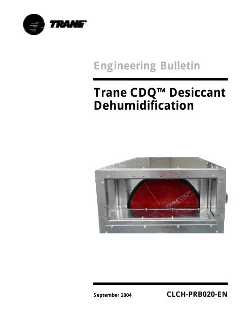
<strong>Engineering</strong> <strong>Bulletin</strong><br />
<strong>Trane</strong> <strong>CDQ</strong>Desiccant<br />
Dehumidification<br />
September 2004 <strong>CLCH</strong>-<strong>PRB020</strong>-<strong>EN</strong>
Preface<br />
This engineering bulletin presents the <strong>Trane</strong> <strong>CDQ</strong> desiccant<br />
dehumidification system. It explains the features and benefits provided by<br />
the <strong>Trane</strong> <strong>CDQ</strong> desiccant wheel, provides a detailed selection procedure,<br />
and reviews specific guidelines to assure an effective cooling and<br />
dehumidifying system design. This material should be reviewed carefully<br />
before beginning the design process.<br />
Please contact your local <strong>Trane</strong> sales engineer for additional information<br />
beyond the scope of this engineering bulletin.<br />
© 2004 American Standard Inc. All rights reserved <strong>CLCH</strong>-<strong>PRB020</strong>-<strong>EN</strong>
Contents<br />
Features and Benefits .........................................................4<br />
Moisture Management in Buildings ................................................................. 4<br />
The <strong>CDQ</strong> System Concept ..................................................5<br />
Overview of Desiccants .....................................................6<br />
Energy Wheels................................................................................................. 6<br />
Active Desiccant Wheels ................................................................................. 6<br />
<strong>Trane</strong> <strong>CDQ</strong> Desiccant Wheel .......................................................................... 8<br />
<strong>CDQ</strong> System Performance ..................................................9<br />
A Basic <strong>CDQ</strong> Air Handler Example .................................................................. 9<br />
<strong>CDQ</strong> System –The Benefits .......................................................................... 10<br />
<strong>CDQ</strong> Performance Data ................................................................................. 11<br />
Typical Achievable Dew Points ................................................................ 11<br />
Latent Capacity ........................................................................................ 13<br />
Pressure Loss .......................................................................................... 14<br />
<strong>CDQ</strong> Air Handler Configurations ...................................... 15<br />
Preheat ........................................................................................................... 15<br />
Location of Outside Air Inlet .......................................................................... 16<br />
Location of Supply Fan................................................................................... 17<br />
Filtration Requirements.................................................................................. 18<br />
Location of Heating Coils ............................................................................... 18<br />
Combining Exhaust-Air Energy Recovery with a <strong>CDQ</strong>Wheel........................ 18<br />
Dedicated Outdoor-Air Systems and a <strong>CDQ</strong> Wheel....................................... 18<br />
A <strong>CDQ</strong> System vs. Active DesiccantSystems ................ 19<br />
<strong>CDQ</strong> Applications .............................................................. 21<br />
35 to45Percent Relative Humidity Spaces................................................... 21<br />
Dry Storage/Archives .............................................................................. 21<br />
Hospital Operating Rooms ....................................................................... 21<br />
Laboratories ............................................................................................. 21<br />
50 to65Percent Relative Humidity Spaces................................................... 21<br />
Schools and Colleges............................................................................... 21<br />
Retail Stores and Restaurants.................................................................. 21<br />
Office Buildings........................................................................................ 21<br />
Equipment Selection .........................................................................................22<br />
Outside Air Conditions ................................................................................... 22<br />
Sizing Cooling Equipment .............................................................................. 22<br />
Sizing Preheat ................................................................................................ 22<br />
Sample Selections.......................................................................................... 22<br />
Example: 55%RH Limit Application, School Classroom w/Constant<br />
Volume AHU ............................................................................................ 22<br />
Example: 35%RH Limit Application, Dry Storage ................................... 25<br />
Wheel Construction .......................................................... 27<br />
Drive System ................................................................................................. 27<br />
Wheel Media .................................................................................................. 27<br />
Wheel Life...................................................................................................... 27<br />
<strong>CLCH</strong>-<strong>PRB020</strong>-<strong>EN</strong> 3
<strong>Trane</strong> <strong>CDQ</strong> wheels can greatly improve the<br />
dehumidification capabilities of an airconditioning<br />
system.<br />
<strong>CDQ</strong> system features and benefits include:<br />
• Increased cooling coil latent<br />
(dehumidification) capacity.<br />
• Lower achievable supply-air dew points.<br />
• Decreased need for reheat.<br />
• Lower unit cooling sensible heat ratios.<br />
• Warmer required chilled water<br />
temperatures.<br />
• Improved energy efficiency for<br />
dehumidification.<br />
• Decreased required cooling capacity<br />
when dehumidifying.<br />
• Eliminates exhaust air as a requirement.<br />
Features<br />
and Benefits<br />
Moisture<br />
Management in<br />
Buildings<br />
Preventing moisture-related<br />
problems in buildings and in HVAC<br />
systems is a shared responsibility<br />
among all parties involved in<br />
building design, specification,<br />
construction, commissioning,<br />
maintenance, and use.<br />
Managing building moisture<br />
involves many components and it is<br />
important to realize that the HVAC<br />
system alone cannot prevent all<br />
moisture-related problems.<br />
A few examples are listed below:<br />
• Building envelope design and<br />
construction (including the<br />
location of vapor barriers)<br />
• Flashing installation<br />
• Roof maintenance<br />
• Quickly repairing leaks<br />
• Proper cleaning techniques<br />
For more information, refer to the<br />
<strong>Trane</strong> “Managing Building<br />
Moisture” application engineering<br />
manual (literature order number<br />
SYS-AM-15).<br />
One component of moisture control<br />
is to limit indoor humidity. When<br />
properly designed and controlled, an<br />
HVAC system can provide effective<br />
dehumidification over a wide range<br />
of conditions. The <strong>Trane</strong><br />
“Dehumidification in HVAC<br />
Systems” application engineering<br />
manual (literature order number<br />
SYS-APM004-<strong>EN</strong>) discusses the<br />
challenges of dehumidifying,<br />
especially at part-load conditions,<br />
and presents several ways to<br />
improve the dehumidification<br />
performance of commonly-used<br />
HVAC systems.<br />
This engineering bulletin introduces<br />
the <strong>Trane</strong> <strong>CDQ</strong> desiccant<br />
dehumidification system and how it<br />
can be used to greatly improve the<br />
dehumidification performance of an<br />
HVAC system.<br />
Note:Please be advised that final<br />
design and application decisions are<br />
your responsibility. <strong>Trane</strong> disclaims<br />
any responsibility for such<br />
decisions.<br />
4 <strong>CLCH</strong>-<strong>PRB020</strong>-<strong>EN</strong>
<strong>CDQ</strong><br />
System Concept<br />
The <strong>Trane</strong> <strong>CDQ</strong> desiccant wheel is<br />
used to enhance the<br />
dehumidification performance of a<br />
traditional cooling coil. The wheel is<br />
configured in series with the coil<br />
(see Figure1) such that the<br />
“regeneration” side of the wheel is<br />
located upstream of the coil and the<br />
“process” side of the wheel is<br />
located downstream of the coil. The<br />
<strong>CDQ</strong> desiccant wheel adsorbs water<br />
vapor from the air downstream of<br />
the cooling coil and then adds it<br />
back into the air upstream of the coil<br />
where the coil removes it through<br />
condensation. This process is<br />
accomplished without the need for a<br />
second regeneration air stream.<br />
Figure 1.<strong>CDQ</strong> dehumidification processes<br />
The addition of the <strong>CDQ</strong> desiccant<br />
wheel to the system enhances the<br />
dehumidification performance of the<br />
traditional cooling coil. The <strong>CDQ</strong><br />
wheel transfers water vapor, and the<br />
cooling coil does all the<br />
dehumidification work in the<br />
system. The latent<br />
(dehumidification) capacity of the<br />
cooling coil increases without<br />
increasing its total cooling capacity.<br />
The system can achieve a lower<br />
supply-air dew point without<br />
lowering the coil temperature.<br />
Unlike a system with a cooling coil<br />
alone, the dew point of the air<br />
leaving the system can be lower<br />
than the coil surface temperature.<br />
<strong>CLCH</strong>-<strong>PRB020</strong>-<strong>EN</strong> 5
Desiccants are substances specially<br />
designed to attract water vapor from<br />
the air. The water vapor is<br />
transferred from the air to the<br />
desiccant through the process of<br />
adsorption. Adsorption occurs at the<br />
molecular level; water vapor<br />
molecules are adsorbed into the<br />
desiccant. Adsorbents are microporous<br />
materials that do not change<br />
phase when they exchange water<br />
vapor. Examples of adsorbents are<br />
activated aluminas, silica gels, and<br />
molecular sieves (zeolites). This is<br />
different than absorbents, which<br />
change phase during this exchange<br />
of water vapor. Examples of<br />
absorbents are hygroscopic salts,<br />
such as lithium chloride. Absorbents<br />
are more subject to chemical change<br />
and are often in liquid form.<br />
Figure 2.Example of desiccant isotherms<br />
Overview<br />
of Desiccants<br />
Adsorbents can vary greatly. Most<br />
people are unaware that there are<br />
hundreds of variations of silica gels,<br />
molecular sieves, and activated<br />
aluminas; each is designed and<br />
manufactured for a specific task.<br />
These different desiccants can be<br />
further categorized based on their<br />
ability to hold water vapor at a<br />
specific temperature and relative<br />
humidity. This characteristic curve is<br />
called the desiccant isotherm. The<br />
typical isotherms of the three basic<br />
categories of desiccants (Types I, II,<br />
and III) are shown in Figure2.<br />
Energy Wheels<br />
Total-energy wheels (also called<br />
enthalpy wheels) are used to<br />
transfer both sensible heat and<br />
moisture (latent heat) between the<br />
outdoor air stream and the exhaust<br />
air stream (see Figure 3). Most totalenergy<br />
wheels use a Type I or Type II<br />
desiccant. The desiccant wheel<br />
rotates quickly—between 20 and 60<br />
rotations per minute—through the<br />
outdoor and exhaust air streams.<br />
When it is hot and humid outdoors,<br />
sensible heat and moisture are<br />
transferred from the outdoor air to<br />
the exhaust air stream, cooling and<br />
dehumidifying the entering outdoor<br />
air. When it is cold and dry outdoors,<br />
sensible heat and moisture are<br />
transferred from the exhaust air to<br />
the outdoor air stream, heating and<br />
humidifying the entering air.<br />
Figure 3. Total energy recovery wheels<br />
Total-energy wheels can<br />
significantly reduce the ventilation<br />
cooling and heating loads, especially<br />
at peak conditions, but they do not<br />
dehumidify the space. Theoretically,<br />
an energy wheel can only be<br />
100 percent effective. The outdoor<br />
air leaving the wheel can only get as<br />
dry as the exhaust air entering side.<br />
The exhaust air comes from the<br />
space. Thus, at best, the outdoor air<br />
leaving the wheel can only get as<br />
dry as the space, but no drier. If<br />
supply air is no drier than the space,<br />
it cannot dehumidify the space. The<br />
system still requires a cooling coil to<br />
dehumidify the space.<br />
6 <strong>CLCH</strong>-<strong>PRB020</strong>-<strong>EN</strong>
Overview of Desiccants<br />
Active Desiccant<br />
Wheels<br />
Active (heat-regenerated) desiccant<br />
wheels use a Type II desiccant. As<br />
the sample isotherm in Figure2<br />
shows, these desiccants can hold a<br />
significant amount of moisture even<br />
when the air stream is very dry. This<br />
is useful when you are trying to<br />
make dry air even drier. TypeII<br />
desiccants are typically used in<br />
industrial and pharmaceutical<br />
applications where dew points of 0°F<br />
or lower may be required.<br />
Like total-energy wheels, active<br />
desiccant wheels use two separate<br />
air streams (see Figure4). The<br />
second “regeneration” air stream<br />
may be the exhaust air stream or a<br />
second outside air stream. A heat<br />
source is used to warm up the air<br />
entering the regeneration side of the<br />
wheel. Adding heat to the<br />
regeneration air allows the wheel to<br />
remove more water vapor from the<br />
air passing through the “process”<br />
side of the wheel. The source of heat<br />
is usually a direct-fired gas burner<br />
because the regeneration air must<br />
be very hot in order to dry out the<br />
process air. Depending on the<br />
Figure 4.Active desiccant wheel<br />
required dew point of the process<br />
air, regeneration air temperatures<br />
typically range from 150°F to 300°F.<br />
The warmer the regeneration air<br />
(OA'') is, the drier the resulting<br />
process air (OA') will be.<br />
Unlike total-energy wheels,<br />
however, active desiccant wheels<br />
rotate very slowly—between 10 and<br />
30 rotations per hour. An active<br />
desiccant wheel is very effective at<br />
removing moisture from the supply<br />
(process) air stream, but for every<br />
ton of latent heat (moisture)<br />
removed, it adds more than one ton<br />
of sensible heat back into the supply<br />
air. The air leaving the supply side of<br />
the wheel is very dry (low dew<br />
point), but its dry-bulb temperature<br />
is usually above 100°F, and it often<br />
must be cooled back down before it<br />
can be used in most applications.<br />
Because of this, active desiccant<br />
wheels are typically only used when<br />
the required supply-air dew point<br />
cannot be achieved with standard<br />
mechanical (cold cooling coil)<br />
equipment.<br />
<strong>CLCH</strong>-<strong>PRB020</strong>-<strong>EN</strong> 7
<strong>CDQ</strong> Desiccant<br />
Wheel<br />
The <strong>Trane</strong> <strong>CDQ</strong> desiccant wheel is<br />
not an enthalpy wheel, nor is it the<br />
same as an active desiccant wheel. It<br />
is configured in series with a cooling<br />
coil, and requires only one air<br />
stream; no exhaust air or second<br />
regeneration air stream is required<br />
(see Figure5).<br />
The <strong>Trane</strong> <strong>CDQ</strong> wheel uses a Type III<br />
desiccant (activated alumina)<br />
chosen specifically for this<br />
application. The ability of the<br />
desiccant to adsorb water vapor is<br />
very high when the relative humidity<br />
of the air is high (see Figure6). Its<br />
ability to hold water vapor greatly<br />
decreases as the relative humidity of<br />
the air drops below 80percent. Air<br />
leaving a cooling coil is generally at<br />
a very high relative humidity (often<br />
greater than 90percent). At this<br />
condition, the <strong>CDQ</strong> desiccant wheel<br />
will have a high affinity for water<br />
vapor and adsorb it from the air that<br />
leaves the cooling coil. When the<br />
wheel rotates into the mixed (or<br />
return) air stream, it will be exposed<br />
to air that is at a much lower relative<br />
humidity (typically 40 to60percent).<br />
At this lower relative humidity, the<br />
desiccant will have a much lower<br />
affinity for water vapor, and it will<br />
release water vapor into the air<br />
stream. The regeneration air stream<br />
does not need to be hot in order to<br />
drive the process. It is driven by the<br />
characteristic of the desiccant<br />
specifically chosen for this<br />
application, which allows the wheel<br />
to be regenerated at low<br />
temperatures.<br />
The <strong>CDQ</strong> desiccant wheel rotates<br />
very slowly—less than one rotation<br />
per minute. Because of this, very<br />
little sensible heat is exchanged. The<br />
increase in the supply-air dry-bulb<br />
temperature is associated with the<br />
amount of heat generated as the<br />
desiccant adsorbs the water vapor.<br />
Overview of Desiccants<br />
Figure 5.Basic <strong>CDQ</strong> air handler<br />
Figure 6.Type III isotherm and <strong>CDQ</strong> application<br />
8 <strong>CLCH</strong>-<strong>PRB020</strong>-<strong>EN</strong>
A Basic <strong>CDQ</strong> Air<br />
Handler Example<br />
The most basic <strong>CDQ</strong> configuration<br />
has return air and outside air mixing<br />
(MA) before it passes through the<br />
regeneration side of the <strong>CDQ</strong><br />
desiccant wheel. Next is the supply<br />
fan blowing into a cooling coil,<br />
followed by the process side of the<br />
wheel and an optional reheat coil.<br />
Below (Figure7) is just one possible<br />
way to obtain this configuration with<br />
a <strong>Trane</strong> M-Series air handler.<br />
Figure 8 shows the system<br />
performance for this unit.<br />
Figure 7.Example of <strong>CDQ</strong> air handler<br />
<strong>CDQ</strong><br />
System Performance<br />
The air leaves the cooling coil (CA)<br />
at a very high relative humidity,<br />
typically about 97 percentRH. The<br />
<strong>CDQ</strong> desiccant wheel adsorbs water<br />
vapor from this air stream, removing<br />
10 grains of water per pound mass<br />
of air in this example. This<br />
adsorption process results in the<br />
addition of some sensible heat,<br />
raising the dry-bulb temperature of<br />
the supply air (SA) by 4°F in this<br />
example. The mixed air entering the<br />
regeneration side of the wheel is at a<br />
lower relative humidity (50 percent).<br />
At this condition, the <strong>CDQ</strong> desiccant<br />
wheel will no longer be able to hold<br />
the water vapor it adsorbed from the<br />
air leaving the cooling coil. The<br />
water vapor is released (desorbed)<br />
off the wheel and into the mixed air<br />
(MA'), upstream of the cooling coil.<br />
This transferred water vapor is then<br />
condensed out of the air stream by<br />
the cooling coil. The resulting supply<br />
air (SA) is 54°F dry bulb with a 44°F<br />
dew point. This low dew point is<br />
achieved with only 50°F air leaving<br />
the cooling coil.<br />
<strong>CLCH</strong>-<strong>PRB020</strong>-<strong>EN</strong> 9
Figure 8.Sample performance and psychrometric plot<br />
<strong>CDQ</strong> System - The<br />
Benefits<br />
The benefits of dehumidifying with a<br />
<strong>CDQ</strong> system compared to cooling<br />
and reheat are evident by examining<br />
the psychrometric plot of both<br />
systems.<br />
Using the <strong>CDQ</strong> wheel enhances the<br />
dehumidification capabilities of a<br />
cooling coil. To remove the same<br />
amount of moisture, a cool-reheat<br />
system would require more cooling<br />
capacity and need to reheat (see<br />
Figure 9). A <strong>CDQ</strong> system would save<br />
cooling and reheat energy and,<br />
depending on the application, may<br />
even allow for downsizing of the<br />
cooling equipment.<br />
The cooling coil SHR, sensible heat<br />
ratio (the ratio of sensible cooling to<br />
total cooling), is also lowered with a<br />
<strong>CDQ</strong> System Performance<br />
<strong>CDQ</strong> system without using reheat.<br />
This helps the unit better match<br />
building loads, especially during<br />
part load conditions and reduces the<br />
need of reheat. The temperature<br />
gain from the wheel is minimal,<br />
typically 3°F to 9°F, thus the system<br />
can cool and dehumidify.<br />
A unique benefit of the <strong>CDQ</strong> system<br />
is that it can deliver a lower supplyair<br />
dew point than the cooling coil<br />
temperature. A cooling coil can<br />
typically dehumidify air to a dew<br />
point that is 5°F to 10°F above the<br />
temperature of the fluid or<br />
refrigerant that flows through its<br />
tubes. For example, 45°F chilled<br />
water (depending on the flow rate<br />
and coil characteristics, of course)<br />
can dehumidify air to a dew point of<br />
50°F to 55°F. By adding a <strong>CDQ</strong><br />
desiccant wheel to the process, the<br />
supply-air dew point can be 0°F to<br />
10°F below the chilled-water<br />
temperature. This can extend the<br />
achievable dew points of traditional<br />
DX or chilled-water systems.<br />
It can also improve the energy<br />
efficiency of chilled-water systems.<br />
Because the chillers can produce<br />
warmer water temperatures to<br />
achieve lower supply-air dew points,<br />
the chiller can be more efficient. A<br />
<strong>CDQ</strong> system may also reduce the<br />
pumping power by allowing reduced<br />
chilled-water flow rates and may<br />
eliminate or reduce the need for<br />
glycol in the system.<br />
Finally, in low dew point<br />
applications, a <strong>CDQ</strong> system may<br />
reduce overall energy use by<br />
eliminating the need for a coil<br />
defrost system or an active (heat<br />
regenerated) desiccant system.<br />
10 <strong>CLCH</strong>-<strong>PRB020</strong>-<strong>EN</strong>
<strong>CDQ</strong> System Performance<br />
Figure 9.Psychrometric plot: A <strong>CDQ</strong> system vs. a cool-reheat system<br />
<strong>CDQ</strong> Performance<br />
Data<br />
The <strong>Trane</strong> <strong>CDQ</strong> selection software<br />
can be used to obtain performance<br />
data on the <strong>CDQ</strong> desiccant wheel.<br />
The sample data in Figure 10 can be<br />
used as a guide to see if a <strong>CDQ</strong><br />
system would be a good fit for your<br />
application.<br />
Typical Achievable<br />
Dew Points<br />
Figure 10 represents the typical<br />
supply-air dew points of a <strong>CDQ</strong> air<br />
handler at nominal airflow rates, as<br />
a function of the cooling coil leaving<br />
air temperature and the entering<br />
mixed-air relative humidity. This<br />
data assumes that the entering<br />
mixed air dew point is higher than<br />
the coil leaving air temperature. If<br />
the entering air dew point is lower<br />
than the coil leaving air temperature,<br />
in many cases, the system will still<br />
remove moisture from the air.<br />
However, one should use the <strong>CDQ</strong><br />
selection software to determine the<br />
expected supply-air dew point.<br />
The lower the relative humidity of<br />
the air entering the regeneration<br />
side of the <strong>CDQ</strong> wheel, the drier the<br />
air will be as it leaves the process<br />
side of the wheel. This is different<br />
than a conventional air-conditioning<br />
system where the achievable dew<br />
point is based on how cold the air is<br />
leaving the cooling coil. For<br />
example, if the mixed air enters the<br />
regeneration side of the <strong>CDQ</strong> wheel<br />
at 80°F dry bulb/60 percent RH, and<br />
the dry-bulb temperature of the air<br />
leaving the cooling coil is 50°F, the<br />
dew point of the air leaving the <strong>CDQ</strong><br />
wheel will be approximately 45°F.<br />
With the same 50°F leaving-coil<br />
temperature, but 80°F dry bulb/40<br />
percentRH mixed air, the supply-air<br />
dew point will be approximately<br />
42°F.<br />
By contrast, in a system with a<br />
cooling coil only (no <strong>CDQ</strong> wheel), if<br />
the dry-bulb temperature of the air<br />
leaving the cooling coil is 50°F, the<br />
supply-air dew point will be slightly<br />
below 50°F and will vary only a little<br />
with this change in mixed-air<br />
relative humidity. To reach the same<br />
dew point as the <strong>CDQ</strong> system, the<br />
cooling coil will not only require<br />
more capacity, but it will likely need<br />
to operate at less efficient<br />
conditions—colder water<br />
temperatures or lower suction<br />
temperatures.<br />
<strong>CLCH</strong>-<strong>PRB020</strong>-<strong>EN</strong> 11
Figure 10.Typical achievable dewpoints<br />
Figure 11.Improvement in cooling coil efficiency<br />
<strong>CDQ</strong> System Performance<br />
12 <strong>CLCH</strong>-<strong>PRB020</strong>-<strong>EN</strong>
The example in Figure11 shows<br />
5,000c<strong>fm</strong> of mixed air at 80°F dry<br />
bulb/40 percentRH, with a target<br />
supply-air dew point of 42°F and an<br />
outdoor dry-bulb temperature of<br />
90°F. Using a cooling coil alone<br />
(without a <strong>CDQ</strong> wheel) requires<br />
30 percent more cooling capacity by<br />
the coil (24tons compared to<br />
18.3tons with a <strong>CDQ</strong> wheel). But<br />
because this example also requires a<br />
colder water temperature (38°F), the<br />
system without a <strong>CDQ</strong> wheel will<br />
require a chiller that has a 50percent<br />
larger nominal capacity (30-ton<br />
chiller compared to a 20-ton chiller<br />
with a <strong>CDQ</strong> wheel). At these<br />
conditions, the system without a<br />
<strong>CDQ</strong> wheel will use 50percent more<br />
power. The <strong>CDQ</strong> benefit not only<br />
occurs at design but also results in<br />
annual energy savings. Most of this<br />
cooling energy is realized because<br />
even though the <strong>CDQ</strong> wheel will add<br />
fan energy, it will save on pump<br />
energy. The Type C1 <strong>CDQ</strong> wheel will<br />
add an additional 1.0bhp in fan<br />
power for this example. However,<br />
the system without a <strong>CDQ</strong> wheel<br />
requires a higher flow rate, as well<br />
as a glycol mixture (because the<br />
chiller has to produce water at such<br />
a low temperature), so it will require<br />
an additional 1.3bhp in pumping<br />
power.<br />
Figure 12.SHR improvement<br />
<strong>CDQ</strong> System Performance<br />
Latent Capacity<br />
Figure 12 shows the sensible heat<br />
ratio (SHR, sensible capacity divided<br />
by the total capacity) of a system<br />
with a cooling coil and a <strong>CDQ</strong> wheel<br />
versus a system with just a cooling<br />
coil. A range of typical mixed-air<br />
conditions is shown along with the<br />
corresponding unit SHR at various<br />
cooling capacities. This figure shows<br />
Figure 13.Latent capacity improvement<br />
that, in most cases, adding the <strong>CDQ</strong><br />
wheel lowers the “unit SHR” by 0.10<br />
to 0.14.<br />
This reduction in unit SHR is not<br />
accomplished by adding heat. It is a<br />
result of increasing the latent<br />
capacity of the coil with the <strong>CDQ</strong><br />
wheel. This increase in latent<br />
capacity is achieved without<br />
increasing the total capacity.<br />
Figure 13 is the same data<br />
<strong>CLCH</strong>-<strong>PRB020</strong>-<strong>EN</strong> 13
epresented in terms of latent<br />
capacity improvement. The latent<br />
capacity improvement at the<br />
examples conditions range from<br />
15 to550percent.<br />
The improvement in latent capacity<br />
makes a <strong>CDQ</strong> system beneficial not<br />
only in low dew point applications<br />
but also in comfort cooling<br />
applications, especially at part load<br />
conditions. For example, at 400c<strong>fm</strong>/<br />
ton, the <strong>CDQ</strong> system will remove<br />
70 percent more water vapor from<br />
80°F/67°F air than a cooling coil<br />
would remove by itself.<br />
Figure 14 shows a comparison of<br />
using a <strong>CDQ</strong> wheel on an example<br />
DX system sized at 400c<strong>fm</strong>/ton. At<br />
this example part-load condition, to<br />
get more dehumidification, the<br />
compressor would run 50percent<br />
longer and the extra sensible<br />
cooling that results from this<br />
extended runtime would need to be<br />
offset by reheat. The <strong>CDQ</strong> unit can<br />
increase the amount of moisture<br />
removed without the need for<br />
reheat. The example in Figure14<br />
shows how adding a <strong>CDQ</strong> wheel is<br />
more efficient than cool-reheat. It<br />
saves compressor energy by<br />
shortening runtime, and it<br />
eliminates the need for reheat.<br />
Pressure Loss<br />
The pressure drop across the <strong>CDQ</strong><br />
wheel is similar to, or less than, a<br />
total-energy (enthalpy) wheel.<br />
Figure 15 is the pressure drop per<br />
pass for the Type C1 <strong>CDQ</strong> wheel.<br />
<strong>CDQ</strong> System Performance<br />
Figure 14.Example: Part load, 400 c<strong>fm</strong>/ton 80 F/67 F EA<br />
Figure 15.Type C1 wheel pressure drop<br />
14 <strong>CLCH</strong>-<strong>PRB020</strong>-<strong>EN</strong>
Figure 16.Sample air handler<br />
configuration<br />
Most applications of the <strong>CDQ</strong> air<br />
handler will have components<br />
configured as described in the<br />
previous examples: outside air and<br />
return air inlets, filter, wheel pass<br />
one, supply fan, cooling coil, wheel<br />
pass two, then optional reheat coil.<br />
<strong>CDQ</strong> Air Handler<br />
Configurations<br />
Preheat<br />
Preheat may be used to obtain lower<br />
supply-air dew points in applications<br />
in which there may be an ample<br />
supply of chilled water available, but<br />
it is not at a cold enough<br />
temperature for the system to<br />
achieve the required dew point.<br />
Figure 8 on page 10 shows that for<br />
entering mixed-air conditions of<br />
80°F dry bulb/55 percentRH, a 40°F<br />
leaving dew point can be achieved if<br />
the air leaves the cooling coil at<br />
47°F. But what if the temperature of<br />
the available chilled water is only<br />
45°F, and with this water<br />
temperature the coil can only<br />
achieve a leaving-air temperature of<br />
50°F? Looking back at Figure 8, if the<br />
relative humidity of the entering<br />
mixed-air could be lowered to 30<br />
percentRH, then the 40°F supply-air<br />
Figure 17.Example: Use of preheat, 5,000 c<strong>fm</strong>, 80°F, 55% mixed air, 40°F dew point<br />
dew point could be achieved with<br />
50°F air leaving the coil. Using a<br />
preheat coil to raise the dry-bulb<br />
temperature of this entering mixed<br />
air by 19°F results in a reduction in<br />
the relative humidity of that air to 30<br />
percentRH (see Figure 17). While<br />
preheating the mixed air does add to<br />
the cooling load, it allows the<br />
system to achieve a lower supply-air<br />
dew point with only 45°F water.<br />
Table1 shows an example of the<br />
condition in Figure17 and how it can<br />
be achieved in three different ways.<br />
In this example, a <strong>CDQ</strong> system with<br />
preheat requires the most cooling<br />
capacity, but the temperature<br />
leaving the cooling coil is the<br />
warmest. Preheat can be modeled<br />
and predicted with <strong>Trane</strong> <strong>CDQ</strong><br />
Performance Software.<br />
<strong>CLCH</strong>-<strong>PRB020</strong>-<strong>EN</strong> 15
Table 1.Comparison of dehumidification methods<br />
Unlike the heat that is required to<br />
regenerate active desiccant systems,<br />
the preheat coil used in a <strong>CDQ</strong><br />
system only raises the temperature<br />
of the air entering the regeneration<br />
side of the wheel by 5°Fto20°F.<br />
Because this temperature is fairly<br />
low (between 80°F and 100°F, for<br />
example), the heat required for<br />
preheat can often be recovered from<br />
the condensing process of the<br />
refrigeration equipment.<br />
Preheat results in a warmer supplyair<br />
dry-bulb temperature, but it also<br />
adds to the cooling coil loads. For<br />
this reason, preheat should be used<br />
only to extend the achievable dew<br />
point of the system, not for<br />
tempering the supply air. If the<br />
supply-air dry-bulb temperature<br />
needs to be higher to prevent overcooling<br />
the space, reheat should be<br />
used instead. The heat required for<br />
reheat, as with preheat, can often be<br />
recovered from the condensing<br />
process of the refrigeration<br />
equipment.<br />
<strong>CDQ</strong> Air Handler Configurations<br />
Cooling Capacity Leaving Coil Dry Bulb Leaving Coil Dew Point Leaving System Dry<br />
Unit Type<br />
Required (Tons)<br />
(°F)<br />
(°F)<br />
Bulb (°F)<br />
Coil Only 27 40 40 40<br />
<strong>CDQ</strong> system 22 47 40 51<br />
<strong>CDQ</strong> system w/ preheat 27 50 40 57<br />
Figure 18.Acceptable outside air inlet locations<br />
Location of Outside<br />
Air Inlet<br />
For mixed-air systems, the outside<br />
air can be introduced either<br />
upstream or downstream of the<br />
regeneration side of the <strong>CDQ</strong> wheel<br />
(see Figure18). Mixing in the<br />
outside air downstream of the<br />
regeneration side of the wheel may<br />
add to the unit foot print and require<br />
the addition of a second filter, but<br />
there are benefits to this<br />
configuration. If precise control of<br />
humidity is desired (rather than<br />
keeping humidity below an upper<br />
limit) this may be the preferred<br />
configuration. If the space is being<br />
maintained at a constant<br />
temperature and a constant relative<br />
humidity, the condition of the air<br />
entering the regeneration side of the<br />
<strong>CDQ</strong> wheel is going to be constant<br />
throughout the year. Therefore, the<br />
wheel will perform the same year<br />
round as long as the temperature of<br />
the air leaving the cooling coil is<br />
constant. A change in the outside air<br />
conditions will change the load on<br />
the cooling coil, but it will not affect<br />
wheel performance.<br />
Mixing in the outside air upstream<br />
or downstream of the regeneration<br />
side of the wheel will slightly change<br />
the required cooling capacity, and<br />
this effect can be modeled using<br />
<strong>Trane</strong> <strong>CDQ</strong> Performance Software. If<br />
the unit is used in a variable air<br />
volume (VAV) system, or if the<br />
percentage of outside air is greater<br />
than 40percent, the outside air<br />
should be mixed in upstream of the<br />
regeneration side of the wheel. This<br />
helps prevent the relative humidity<br />
of the air entering the regeneration<br />
side of the wheel from increasing<br />
too much.<br />
16 <strong>CLCH</strong>-<strong>PRB020</strong>-<strong>EN</strong>
Location of<br />
Supply Fan<br />
The location of the supply fan will<br />
affect system performance.<br />
Figure 19 represents possible<br />
configurations. The order of<br />
components is an important factor.<br />
The higher the relative humidity<br />
entering the process (adsorption)<br />
side of the wheel, the better it will<br />
perform. Therefore, whenever<br />
possible, the supply fan should be<br />
located upstream of the cooling coil,<br />
because the addition of fan heat<br />
downstream of the cooling coil will<br />
lower the relative humidity and will<br />
reduce the amount of water vapor<br />
the <strong>CDQ</strong> wheel adsorbs.<br />
The static pressure to which the<br />
wheel is exposed can have a more<br />
significant effect. The regeneration<br />
side of the wheel should be under<br />
negative pressure, and the process<br />
(adsorption) side should be under<br />
positive pressure, so any air that<br />
leaks through the wheel (cross<br />
leakage) travels from the process<br />
side to the regeneration side. Even<br />
though cross leakage has a<br />
negligible effect on the performance<br />
of the fan or coil, it has a more<br />
significant effect on wheel<br />
performance. Therefore, the supply<br />
fan should be located downstream<br />
of the regeneration side of the<br />
wheel, but upstream of the process<br />
side.<br />
<strong>CDQ</strong> Air Handler Configurations<br />
Figure 19.Supply fan locations<br />
Draw-Thru/Blow-Thru<br />
Wheel, Blow-Thru Coil<br />
Recommended<br />
configuration for optimum<br />
performance<br />
Draw-Thru/Blow-Thru<br />
Wheel, Draw-Thru Coil<br />
Not recommend for low dew<br />
point applications<br />
Acceptable in comfort<br />
cooling applications where<br />
packaged equipment<br />
dictates this configuration<br />
Draw-Thru Wheel, Draw-<br />
Thru Coil<br />
Not recommended<br />
Blow-Thru Wheel, Blow-<br />
Thru Coil<br />
Not recommended<br />
<strong>CLCH</strong>-<strong>PRB020</strong>-<strong>EN</strong> 17
Filtration<br />
Requirements<br />
Minimal filtration is required for<br />
efficient operation of the <strong>Trane</strong> <strong>CDQ</strong>.<br />
At least 30percent efficient flat<br />
throwaway filters are recommended<br />
upstream of the first wheel pass<br />
(regeneration side). These filters will<br />
catch larger size particles. Smaller<br />
particles most likely will pass<br />
through the wheel’s air passages.<br />
Higher efficiency filters may be used<br />
if desired. In applications where oils<br />
or aerosol are present, they should<br />
be removed from the air before<br />
being introduced to the <strong>CDQ</strong> wheel.<br />
Unlike dust and other particles,<br />
aerosols can obstruct the pores of a<br />
desiccant and significantly degrade<br />
its performance.<br />
Location of Heating<br />
Coils<br />
If a preheat coil is used to enhance<br />
the <strong>CDQ</strong> wheel performance, it must<br />
be located upstream of the<br />
regeneration side of the wheel. If the<br />
preheat coil will be used for winter<br />
heating only (not for<br />
dehumidification), it can be placed<br />
either upstream or downstream of<br />
the regeneration side of the wheel.<br />
<strong>CDQ</strong> Air Handler Configurations<br />
If a reheat coil is used, it should be<br />
placed downstream of the process<br />
side of the wheel so that it can be<br />
used during dehumidification.<br />
Combining Exhaust-<br />
Air Energy Recovery<br />
with a <strong>CDQ</strong> Wheel<br />
The <strong>Trane</strong> <strong>CDQ</strong> system does not<br />
require a separate exhaust air<br />
stream to regenerate the desiccant,<br />
so recovering energy from the<br />
exhaust air stream can easily be<br />
used in conjunction with a <strong>CDQ</strong><br />
wheel. Figure 20 shows a totalenergy<br />
recovery wheel being used<br />
to precondition the entering outdoor<br />
air. As with systems without a <strong>CDQ</strong><br />
wheel, the total energy will reduce<br />
required cooling and heating<br />
capacity of the system. In this<br />
configuration, the exhaust air only<br />
passes through the total-energy<br />
wheel; it does not pass through the<br />
<strong>CDQ</strong> wheel. The <strong>CDQ</strong> wheel<br />
operates the same as in the basic<br />
system.<br />
Figure 20.An example configuration for mixed air <strong>CDQ</strong> AHU with energy wheel<br />
Dedicated Outdoor-<br />
Air Systems and a<br />
<strong>CDQ</strong> Wheel<br />
Using a separate, dedicated unit to<br />
dehumidify all of the outside air for<br />
the system and drying that air out<br />
far enough that it also offsets the<br />
space latent loads often requires a<br />
dedicated outdoor-air unit to deliver<br />
air at a lower dew point than a<br />
conventional unit. A <strong>CDQ</strong> system<br />
can help achieve these lower dew<br />
point conditions.<br />
However, in order to achieve low<br />
dew point in dedicated outdoor-air<br />
units, a preheat coil will often be<br />
required for part-load conditions.<br />
When the relative humidity of the<br />
entering outdoor air is very high<br />
(such as on a mild, rainy day), the<br />
preheat coil is required to lower the<br />
relative humidity of the air before it<br />
enters the regeneration side of the<br />
<strong>CDQ</strong> wheel.<br />
The need of preheat can often be<br />
eliminated, and the needed cooling<br />
capacity can be reduced, if a totalenergy<br />
wheel is used in conjunction<br />
with the <strong>CDQ</strong> wheel (see Figure20).<br />
The total-energy wheel can transfer<br />
moisture from the outdoor air to the<br />
exhaust air, thus lowering the<br />
relative humidity of the outdoor air<br />
before it enters the <strong>CDQ</strong> wheel.<br />
18 <strong>CLCH</strong>-<strong>PRB020</strong>-<strong>EN</strong>
Active (heat-generated) desiccant<br />
systems use a high heat source and<br />
a second air stream to remove<br />
moisture from the supply air. A <strong>CDQ</strong><br />
system uses a traditional cooling<br />
coil to remove moisture. Active<br />
desiccant wheels typically require<br />
1800–2000Btu of regeneration heat<br />
per pound mass of water removed.<br />
Figure 21 is an example of an active<br />
desiccant system at the same<br />
conditions as the <strong>CDQ</strong> example<br />
shown in Figure 17. Air leaves the<br />
process side of the wheel (MA') dry,<br />
but at 138°F dry-bulb temperature.<br />
A <strong>CDQ</strong> System vs. Active<br />
Desiccant Systems<br />
Active desiccant systems use<br />
significantly more heat than<br />
standard cool-reheat or <strong>CDQ</strong><br />
systems. The energy cost for this<br />
amount of heat can be high; thus<br />
these systems are usually reserved<br />
for applications where there is a<br />
high heat source available from<br />
onsite power generation or an<br />
industrial process. Also, active<br />
desiccant systems are used where<br />
gas is the desired main energy<br />
source. As the above example<br />
shows, more cooling capacity is<br />
often required at design than with<br />
other methods. This cooling may be<br />
at a warmer coil temperature, but<br />
the extra energy costs of heating the<br />
regeneration air to 280°F more than<br />
offset any energy savings. At these<br />
example conditions, an active<br />
desiccant system uses 33 percent<br />
more cooling than the <strong>CDQ</strong> system<br />
with a 47°F leaving coil temperature.<br />
Also, when considering equivalent<br />
supply air temperatures, the active<br />
desiccant system uses 10 times<br />
more preheat than the <strong>CDQ</strong> system<br />
would need in reheat to obtain 57°F<br />
supply temperature, and the reheat<br />
in the <strong>CDQ</strong> example could be<br />
recovered condenser heat.<br />
Figure 21.Example: Active desiccant system (eff = 1,950 Btu/lbm of water) 5,000 c<strong>fm</strong>, 80°F, 55% mixed air, 40°F supply-air<br />
dew point<br />
<strong>CLCH</strong>-<strong>PRB020</strong>-<strong>EN</strong> 19
A <strong>CDQ</strong> System vs. Active DesiccantSystems<br />
Table 2.Comparison of methods: 5,000 c<strong>fm</strong>, 80 F/55% RH vs. 57°F/40°F dew point<br />
Cooling Capacity Coil Leaving Air Unit Leaving Air Unit Leaving Air Preheat Reheat Required<br />
Unit Type Required (Tons) Temperature (F) Temperature (F) Dew Point (F) Required (MBH) (MBH)<br />
Coil only 33 40 57 40 – 92<br />
<strong>CDQ</strong> unit 28 47 57 40 – 33<br />
<strong>CDQ</strong> w/ preheat 34 50 57 40 103 –<br />
Active desiccant 36 57 57 40 311 –<br />
20 <strong>CLCH</strong>-<strong>PRB020</strong>-<strong>EN</strong>
The <strong>CDQ</strong> system can be applied in<br />
most commercial applications that<br />
require humidity control. This<br />
includes spaces that need to be<br />
maintained between<br />
35 to65percent relative humidity.<br />
The benefit of using a <strong>CDQ</strong> system<br />
versus cool-reheat will vary by<br />
application, but the benefits of<br />
higher latent capacity per ton of total<br />
capacity, lower achievable supplyair<br />
dew point, and reduced reheat<br />
energy will be seen through the<br />
range of applications.<br />
35 to 45 Percent<br />
Relative Humidity<br />
Spaces<br />
The <strong>CDQ</strong> system provides the most<br />
benefit in 35to 45percent relative<br />
humidity applications. This range of<br />
space relative humidity requires that<br />
the supply-air dew point be 30°F to<br />
48°F. The primary benefit of using a<br />
<strong>CDQ</strong> system in these applications is<br />
the ability to use warmer coil<br />
temperatures (warmer chilled-water<br />
temperatures or higher suction<br />
temperatures) than would be<br />
required by another system. Dry<br />
storage/archives, hospital operating<br />
rooms, and laboratories are just a<br />
few 35 to45percent relative<br />
humidity applications that may<br />
benefit from a <strong>CDQ</strong> system.<br />
Dry Storage/Archives<br />
This space type has a small latent<br />
load in the space and requires very<br />
little ventilation air to be introduced.<br />
The challenge for humidity control is<br />
keeping the space humidity level at<br />
the desired low level. Since the<br />
mixed-air relative humidity is low,<br />
the <strong>CDQ</strong> desiccant wheel will be<br />
operating at its most efficient<br />
conditions to help lower the supplyair<br />
dew point. This will raise the<br />
required coil temperature and also<br />
lower the need for reheat.<br />
<strong>CDQ</strong><br />
Applications<br />
Hospital Operating Rooms<br />
Operating rooms are not only kept at<br />
a low relative humidity but also at<br />
cooler temperatures, a good fit for a<br />
<strong>CDQ</strong> system. The improved latent<br />
removal capacity not only reduces<br />
the required cooling needed but the<br />
lower supply-air dew points can<br />
eliminate the need for a secondary<br />
refrigeration coil or a heatregenerated<br />
active desiccant<br />
system. Because active desiccant<br />
systems provide hot air (which<br />
would then require a significant<br />
amount of post-cooling), the use of a<br />
<strong>CDQ</strong> system in this application can<br />
produce significant energy savings.<br />
Laboratories<br />
A <strong>CDQ</strong> system can help achieve the<br />
lower relative humidity needed for<br />
laboratories. Because the exhaust air<br />
often contains contaminants, totalenergy<br />
(enthalpy) recovery from the<br />
exhaust air is usually not<br />
permissible. A <strong>CDQ</strong> system can<br />
improve energy efficiency and latent<br />
removal from the space without the<br />
need to use the exhaust air stream.<br />
50 to 65 Percent<br />
Relative Humidity<br />
Spaces<br />
Most of the benefits of a <strong>CDQ</strong><br />
system are also realized in these<br />
applications, particularly at part load<br />
conditions. The primary benefit in<br />
these applications is an increased<br />
latent capacity and lower SHR,<br />
which allows the unit to better<br />
match the space dehumidification<br />
requirements. Schools and colleges,<br />
retail stores and restaurants, and<br />
office buildings are just a few<br />
50 to65percent relative humidity<br />
applications that may benefit from a<br />
<strong>CDQ</strong> system.<br />
Schools and Colleges<br />
Because of the high occupancy level<br />
of classrooms, the space latent load<br />
can be high. This load occurs year<br />
round, which results in a lower SHR<br />
at part load conditions. A <strong>CDQ</strong> air<br />
handler can be used to help achieve<br />
the higher latent capacity needed for<br />
classrooms. The system can be<br />
either constant volume or variable<br />
air volume (VAV). Humidity levels in<br />
schools can elevate during<br />
weekends and other times when the<br />
buildings are unoccupied. The same<br />
air handler can be used as a<br />
recirculating dehumidifier to keep<br />
the humidity levels under control<br />
during unoccupied hours.<br />
Retail Stores and<br />
Restaurants<br />
As shown in the example in<br />
Figure 14, using a <strong>CDQ</strong> air handler<br />
with a DX system can provide better<br />
part-load dehumidification without<br />
requiring as much cooling or reheat<br />
energy as a cool-reheat system.<br />
Office Buildings<br />
A constant volume or VAV system<br />
can be enhanced to get better<br />
humidity control in the space. A <strong>CDQ</strong><br />
system can also be helpful in offices<br />
designed with under-floor air<br />
distribution. Air delivered at floor<br />
level is at a warmer dry-bulb<br />
temperature (typically around 65°F).<br />
This can create a dehumidification<br />
challenge in many climates. A <strong>CDQ</strong><br />
system can deliver air at 65°F drybulb<br />
temperature, and at a dew<br />
point of 55°F to 58°F, without the<br />
need for overcooling and reheat (or<br />
overcooling and mixing in bypassed<br />
return air).<br />
<strong>CLCH</strong>-<strong>PRB020</strong>-<strong>EN</strong> 21
Outside Air<br />
Conditions<br />
As with any system being designed,<br />
the worst expected conditions the<br />
system will see should be examined.<br />
When designing to control humidity<br />
with or without a <strong>CDQ</strong> system, the<br />
climatic data for the worst<br />
dehumidification day as well as the<br />
worst cooling day should be<br />
examined. ASHRAE publishes<br />
climatic data for various geographic<br />
locations around the world. The<br />
severity of the design outdoor<br />
conditions selected is dependent on<br />
how critical it is to keep the space at<br />
the desired indoor conditions. In the<br />
example below (Table3), outdoor<br />
design conditions for Atlanta, GA,<br />
show a cooling design day of 91°F<br />
dry bulb and 74°F wet bulb. This is a<br />
humidity ratio of 99 grains per<br />
pound mass (gr/lbm) of dry air. The<br />
dehumidification design day is<br />
cooler, 81°F, but it is significantly<br />
more humid with 123gr/lbm.<br />
Sizing Cooling<br />
Equipment<br />
Unlike conventional equipment, the<br />
dew point of the supply air in a <strong>CDQ</strong><br />
system is not equal to the dew point<br />
of the air leaving the cooling coil.<br />
The required cooling coil capacity<br />
and air temperature leaving the coil<br />
are determined by the <strong>CDQ</strong> wheel<br />
Equipment<br />
Selection<br />
performance. The <strong>CDQ</strong> performance<br />
program can be used to determine<br />
the required coil capacity based on<br />
the required supply-air dew point,<br />
dry-bulb temperature, and airflow.<br />
Performance runs should be<br />
completed for cooling design day,<br />
dehumidification design day, and<br />
possibly even a warm, rainy day.<br />
This will confirm that the cooling<br />
equipment is sized appropriately. In<br />
many comfort-cooling applications,<br />
the <strong>CDQ</strong> wheel may only operate at<br />
part-load conditions. For these and<br />
other cases, it is a good idea to<br />
check the performance at a part-load<br />
condition to highlight the benefits of<br />
a <strong>CDQ</strong> system.<br />
Sizing Preheat<br />
To size the preheat coil, <strong>CDQ</strong> system<br />
performance should be calculated at<br />
the dehumidification design day.<br />
Performance should also be<br />
calculated at the highest entering<br />
relative humidity that can be<br />
expected. This typically is at a warm<br />
rainy day (for example, 70°F dry bulb<br />
and a very high relative humidity).<br />
The <strong>CDQ</strong> performance program will<br />
do this calculation for whatever<br />
conditions are input.<br />
Table 3.Example: ASHRAE Fundamentals Climatic Data tables<br />
(Source: 2001 ASHRAE Handbook, Fundamentals, Inch-Pound Edition<br />
Sample Selections<br />
Example: 55% RH Limit Application,<br />
School Classroom w/Constant<br />
Volume AHU<br />
• Location = Jacksonville, FL<br />
• Space Conditions = 74°F dry<br />
bulb, 55% RH upper limit<br />
• Supply Air Flow = 1,500 c<strong>fm</strong><br />
• Outside Air Flow = 450c<strong>fm</strong><br />
• Required Supply Air Conditions:<br />
– @ 1% Cooling Design OA (96°F<br />
dry bulb/78°F wet bulb) => SA =<br />
56°F dry bulb, 64 gr/lbm<br />
– @ 1% Dehumidification Design<br />
OA (84°F dry bulb/78°F wet bulb)<br />
=> SA = 63°F dry bulb, 64 gr/lbm<br />
A supply-air humidity ratio of 64 gr/<br />
lbm is equivalent to a 55°F dewpoint<br />
temperature. At cooling design<br />
conditions, this is close to the<br />
supply-air dry-bulb temperature,<br />
thus at cooling design day the <strong>CDQ</strong><br />
system isn’t needed to maintain<br />
space RH at or below<br />
55 percent...just 4.8tons of cooling.<br />
At dehumidification design<br />
conditions, a <strong>CDQ</strong> system could be<br />
used to save cooling and reheat<br />
energy. At dehumidification design<br />
conditions, only 4.4tons of cooling<br />
is needed, preventing the need to<br />
upsize the cooling equipment (which<br />
would have been required in a coolreheat<br />
system without the <strong>CDQ</strong><br />
wheel). For the <strong>CDQ</strong> system, no<br />
reheat is needed at the<br />
dehumidification design conditions.<br />
22 <strong>CLCH</strong>-<strong>PRB020</strong>-<strong>EN</strong>
Equipment Selection<br />
Figure 22.<strong>CDQ</strong> Performance Program example for dehumidification design conditions<br />
Table 4.Output summary<br />
Wheel Cooling (tons) SA DB SA Dew Point<br />
@1% Cooling Off 4.8 56°F 55°F<br />
@1% Dehumidification On 4.5 63°F 55°F<br />
<strong>CLCH</strong>-<strong>PRB020</strong>-<strong>EN</strong> 23
Equipment Selection<br />
Figure 23.Sample <strong>CDQ</strong> Performance Program output example for dehumidification design conditions<br />
24 <strong>CLCH</strong>-<strong>PRB020</strong>-<strong>EN</strong>
Equipment Selection<br />
Providing 64gr/lbm (55°F dew point)<br />
air from the unit will require reheat<br />
for conditions that require the<br />
supply air to be warmer than 63°F<br />
dry bulb. If up to room neutral<br />
temperature (74°F) is needed, the<br />
reheat coil needs to be sized for an<br />
11°F temperature rise. This could be<br />
provided by hot gas reheat. This is a<br />
significant improvement over a coolreheat<br />
system, which would require<br />
reheat anytime the required supply<br />
air temperature was greater than<br />
56°F.<br />
Table 5.Output summary<br />
Sample Selections<br />
Example: 35% RH Limit Application,<br />
Dry Storage<br />
• Location = New York, NY<br />
• Space Conditions = 68°F dry<br />
bulb, 35% RH upper limit<br />
• Supply Air Flow = 8,800 c<strong>fm</strong><br />
• Outside Air Flow = 700c<strong>fm</strong><br />
• Required Supply Air Conditions:<br />
– @ 1% Cooling Design OA (88°F<br />
dry bulb/72°F wet bulb) =>SA =<br />
52°F dry bulb, 32 gr/lbm (36°F<br />
dew point)<br />
– @ 1% Dehumidification Design<br />
OA (80°F dry bulb/120gr/lbm) =><br />
SA = 52°F dry bulb, 32gr/lbm<br />
(36°F dew point)<br />
In this example, the cooling capacity<br />
will be sized based on the<br />
dehumidification design conditions.<br />
Wheel Cooling (tons) SA DB SA Dew Point<br />
@1% Cooling On 21.0 51.7°F 36.7°F<br />
@1% Dehumidification On 22.2 51.0°F 36.7°F<br />
<strong>CLCH</strong>-<strong>PRB020</strong>-<strong>EN</strong> 25
Equipment Selection<br />
Figure 24.Sample <strong>CDQ</strong> performance program output example for dehumidification design conditions 35% RH application<br />
26 <strong>CLCH</strong>-<strong>PRB020</strong>-<strong>EN</strong>
Wheel<br />
Construction<br />
Depending on the wheel type, the<br />
construction may vary. Contact your<br />
local <strong>Trane</strong> sales engineer for<br />
complete mechanical specifications.<br />
Drive System<br />
The wheel requires a fractional<br />
horsepower gear motor that rotates<br />
the wheel using a perimeter contact<br />
belt. The rotation speed of the wheel<br />
is very slow. As an example, the<br />
Type C1 wheel uses a 1/80HP,<br />
0.3 FLA, 115 V motor. Where<br />
possible, <strong>CDQ</strong> desiccant wheels<br />
have permanently-lubricated<br />
bearings. On larger wheels, pillow<br />
block bearings may be used.<br />
Wheel Media<br />
The desiccant is not applied as a<br />
glued-on surface coating, so it is not<br />
susceptible to erosion, abrasion, or<br />
de-lamination. The desiccant is<br />
integral to the media, and spokes are<br />
used to hold the wheel rigid. To<br />
minimize cross leakage from one<br />
side of the wheel to the other, the<br />
wheel includes both a circumference<br />
seal (as an air block-off around the<br />
perimeter) and an inner diametric<br />
seal (separating regeneration and<br />
process sides).<br />
Wheel Life<br />
Unlike active desiccant wheels that<br />
are subjected to large temperature<br />
swings, the <strong>CDQ</strong> wheel sees more<br />
moderate swings in temperature<br />
and humidity, similar to total-energy<br />
wheels. Life expectancy of the <strong>CDQ</strong><br />
wheel media is similar to that of<br />
energy wheels. The wheel should<br />
not be subject to oils or aerosols that<br />
could coat the wheel and clog pores,<br />
greatly reducing the effective life of<br />
the wheel.<br />
<strong>CLCH</strong>-<strong>PRB020</strong>-<strong>EN</strong> 27
<strong>Trane</strong><br />
A business of American Standard Companies<br />
www.trane.com<br />
For more information, contact your local <strong>Trane</strong><br />
office or e-mail us at comfort@trane.com<br />
Literature Order Number <strong>CLCH</strong>-<strong>PRB020</strong>-<strong>EN</strong><br />
Date September 2004<br />
Supersedes New<br />
Stocking Location Inland<br />
<strong>Trane</strong> has a policy of continuous product and product data improvement and reserves the right to<br />
change design and specifications without notice. <strong>Trane</strong> believes the statements presented here to<br />
be accurate. However, final design and application diecisions are not the responsibility of <strong>Trane</strong>.<br />
<strong>Trane</strong> disclaims any responsibility for action taken on the material presented.


