WSHP-DS-6 March 2000 Water Source Heat Pump ... - SeekPart.com
WSHP-DS-6 March 2000 Water Source Heat Pump ... - SeekPart.com
WSHP-DS-6 March 2000 Water Source Heat Pump ... - SeekPart.com

You also want an ePaper? Increase the reach of your titles
YUMPU automatically turns print PDFs into web optimized ePapers that Google loves.
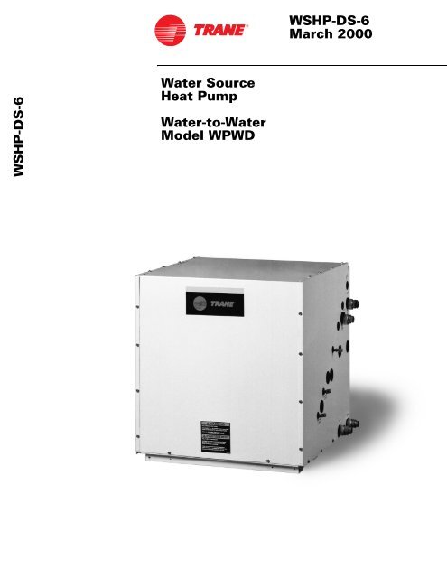
<strong>WSHP</strong>-<strong>DS</strong>-6<br />
<strong>Water</strong> <strong>Source</strong><br />
<strong>Heat</strong> <strong>Pump</strong><br />
<strong>Water</strong>-to-<strong>Water</strong><br />
Model WPWD<br />
<strong>WSHP</strong>-<strong>DS</strong>-6<br />
<strong>March</strong> <strong>2000</strong>
©An American Standard Company<br />
Introduction<br />
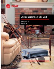
The WPWD product is a heating<br />
and cooling hydronic fluid water-towater<br />
heat pump capable of producing<br />
water temperature up to<br />
130 F or temperatures down to<br />
25 F. This extended operating<br />
range offers great opportunities in<br />
<strong>com</strong>mercial, residential and industrial<br />
applications.<br />
There are many load side applications<br />
for which the WPWD is suited.<br />
Typical usages include:<br />
q Hydronic baseboard heating<br />
q Radiant slab heating<br />
q Space heating or cooling with<br />
Trane fan coils<br />
q Ice and snow removal<br />
q High volume water heating (non<br />
potable)<br />
q Boiler replacement (@130 F)<br />
2<br />
In the heating mode, the water-towater<br />
unit efficiently extracts heat<br />
from a water source (source side)<br />
such as a well, lake, boiler/tower<br />
loop or closed ground loop heat-exchanger,<br />
then transfers the heat to<br />
another flow of water (load side).<br />
The amount of heat added to the<br />
load side is greater than the<br />
amount taken from the source side.<br />
The electrical energy supplied to<br />
the <strong>com</strong>pressor is added to the output<br />
heat of <strong>com</strong>pression.<br />
The Trane water-to-water product<br />
package includes:<br />
q High efficient scroll <strong>com</strong>pressor<br />
q Compressor protection<br />
q <strong>Water</strong> to refrigerant condensing<br />
coil<br />
q Freeze protection<br />
q <strong>Water</strong> to refrigerant evaporator<br />
coil<br />
q Expansion valve<br />
q Filter Drier<br />
q Reversing Valve<br />
q Internal desuperheater<br />
(optional)
Introduction 2<br />
Features and Benefits 4<br />
Model Number Description 7<br />
General Data 8<br />
Application Considerations 9<br />
Electrical Data 18<br />
Performance Data 19<br />
Dimensional Data 25<br />
Wiring Diagram 28<br />
Accessory Options 30<br />
Mechanical Specifications 31<br />
3<br />
Table<br />
of<br />
Contents
Features<br />
and<br />
Benefits<br />
General<br />
The water source heat pump model<br />
WPWD (water-to-water) offers a<br />
range of capacities from 2 tons to 6<br />
tons. All units are housed in one<br />
standard <strong>com</strong>pact cabinet.<br />
Cabinet<br />
The cabinet, which allows easy access<br />
for installation and service, is<br />
constructed of heavy gauge metal.<br />
The cabinet finish is produced by a<br />
corrosion resistant electrostatic<br />
powder paint coating in the color<br />
“soft dove”.<br />
The top half of the diagonal cabinet<br />
is removable for access to the internal<br />
<strong>com</strong>ponents by removing two<br />
screws. (See Figure 1).<br />
Figure 1: Unit access<br />
Insulation<br />
To reduce condensation and <strong>com</strong>pressor<br />
noise, the cabinets are insulated<br />
with 1/2-inch thick,<br />
neoprene backed, acoustical fiberglass<br />
insulation.<br />
Compressor<br />
The model WPWD contains a high<br />
efficiency scroll <strong>com</strong>pressor for reliable<br />
and efficient operation. The<br />
scroll <strong>com</strong>pressor’s unique design<br />
lends itself to having one of the lowest<br />
sound levels in the industry.<br />
The <strong>com</strong>pressor is internally isolated<br />
and placed on a stiff base plate<br />
designed to further reduce vibration<br />
noise. As an added benefit, the<br />
4<br />
General<br />
WPWD cabinet includes full length<br />
channel stiffeners underneath the<br />
unit.<br />
<strong>Heat</strong> Exchanger<br />
The water to refrigerant heat exchangers<br />
are made of stainless<br />
steel brazed plate. This design provides<br />
a larger amount of surface<br />
area for heat exchange between<br />
the water and the refrigerant. (See<br />
Figure 2 for cut-away).<br />
.<br />
Figure 2: Brazed plate heat exchanger<br />
Piping<br />
All low-side copper tubing in the refrigeration<br />
circuit is insulated to prevent<br />
condensation at low entering<br />
liquid temperatures.<br />
Filter Drier<br />
A filter drier is provided in each unit<br />
for dehydration and cleaning of the<br />
refrigeration circuit. This feature<br />
adds to the unit life.<br />
Expansion Valve<br />
As standard, Trane provides a balanced<br />
port thermal expansion<br />
valve. This valve precisely meters<br />
the refrigerant flow through the circuitry<br />
to achieve the desired heating<br />
or cooling over a wide range of<br />
fluid temperatures.<br />
<strong>Water</strong> Connections<br />
All water connections feature<br />
1-inch brass swivel connectors. Because<br />
the connectors are swivel, a<br />
back-up wrench is not necessary<br />
when tightening.
24 Volt Controls<br />
All electrical controls and safety devices<br />
are factory wired, tested, and<br />
mounted in the unit. The control<br />
package includes:<br />
q Compressor contactor<br />
q 24 Volt transformer<br />
q Lockout relay<br />
q Compressor run capacitor (1phase<br />
units only)<br />
q Reversing valve coil (For heat<br />
pump only)<br />
q Fuse (for desuperheater)<br />
A terminal strip with 1/4” fork connections<br />
will be provided for field<br />
thermostat control wiring. (See Figure<br />
3).<br />
Safety Devices<br />
Each Trane water-to-water unit contains<br />
safety devices to prevent <strong>com</strong>pressor<br />
damage. These include:<br />
q Low pressure switch<br />
q High pressure switch<br />
q Temperature sensor (freezestat)<br />
q Internal overload protection<br />
Low Pressure Switch<br />
The low pressure switch prevents<br />
<strong>com</strong>pressor operation under low<br />
charge or in excessive loss of<br />
charge situations. This device is set<br />
to activate at refrigerant pressures<br />
of 35 psig when a 35 F low temperature<br />
detection thermostat is applied.<br />
An optional 7 psig pressure<br />
switch is available when using a 20<br />
F temperature low temperature detection<br />
thermostat.<br />
High Pressure Switch<br />
For internal overload protection,<br />
Trane provides a high pressure<br />
switch. This de-energizes the <strong>com</strong>pressor<br />
when discharge pressure<br />
be<strong>com</strong>e excessive.<br />
Features<br />
and<br />
Benefits<br />
Lockout<br />
Relay<br />
Compressor<br />
Run Capacitor<br />
High Voltage<br />
Low Voltage<br />
Low Temperature<br />
Detection Thermostat<br />
The low water temperature detection<br />
thermostat is provided to protect<br />
the water-to-refrigerant heat<br />
exchanger from freezing. This device<br />
prevents <strong>com</strong>pressor operation<br />
if leaving water temperature is<br />
below 35 F. An optional 20 F temperature<br />
thermostat may be applied<br />
for low water temperatures where<br />
an appropriate antifreeze solution is<br />
used.<br />
5<br />
Controls<br />
2 Amp Fuse<br />
(for use with<br />
desuperheater<br />
option)<br />
Thermostat<br />
50 VA Transformer<br />
24 VAC Contactor<br />
Lockout Relay<br />
Ground<br />
Low Voltage<br />
10 Pole Terminal<br />
Strip<br />
Figure 3: Controls<br />
When the safety controls are activated<br />
to prevent <strong>com</strong>pressor short<br />
cycling, the lockout relay (circuit)<br />
can be reset at the thermostat, or by<br />
cycling power to the unit.<br />
Thermostat Hook-up<br />
Low voltage and high voltage<br />
knockouts are provided in the top<br />
half of the unit. All control wiring to<br />
the unit should be 24 Volt.<br />
(See Figure 4 for termination<br />
points).<br />
24V Power<br />
Compressor<br />
Reversing Valve<br />
(energized in clg)<br />
Figure 4: Typical thermostat termination points
Desuper-out<br />
Desuper-in<br />
Features<br />
and<br />
Benefits<br />
Desuperheater Option<br />
The desuperheater option is a heat<br />
recovery system packaged within<br />
the water-to-water unit. This option<br />
captures heat energy from the heat<br />
pump for considerable cost savings<br />
all year. Since it is active in either<br />
operating mode, it can provide hot<br />
water at a reduced cost while in<br />
heating or virtually free hot water<br />
while in cooling.<br />
Standard equipment includes:<br />
q Desuperheater (heat<br />
exchanger)<br />
q Circulating pump<br />
q Entering water temperature<br />
detector (125 F stops pump)<br />
q Discharge refrigerant<br />
temperature detector (145 F<br />
starts pump)<br />
q Fuse<br />
q <strong>Water</strong> heater hook-up kit<br />
Isolation<br />
Valves<br />
(by others)<br />
6<br />
<strong>Heat</strong><br />
Recovery<br />
The unit employs a circulating pump<br />
to move water through a double wall<br />
heat exchanger. It then returns the<br />
heated water to the water tank. This<br />
water is heated by superheated refrigerant<br />
discharge gas from the<br />
<strong>com</strong>pressor. This heat energy can<br />
now be utilized as a cost savings in<br />
water heating.<br />
Circulating <strong>Pump</strong><br />
The pump is a circular, single stage<br />
open system pump. Its specifications<br />
include:<br />
q 1/25 HP (horsepower)<br />
from Desuperheater<br />
to Desuperheater<br />
q 230 Volt / 60 Hertz / 1 phase<br />
q 90 Watts<br />
q .40 Amps<br />
q 2865 rpm (revolutions per<br />
minute)<br />
q 2 MF (microfarad) / 400 Volt<br />
capacitor<br />
The pump contains a minimum fluid<br />
temperature rating of 50 F, a maximum<br />
fluid temperature (open system)<br />
of 140 F, and a maximum<br />
working pressure of 145 psi.<br />
Hot water<br />
(Supply)<br />
<strong>Water</strong> heater<br />
hook-up kit with<br />
drain valve<br />
Cold water<br />
(Supply)
Digits 1 & 2: Product Type<br />
WP = Trane Commercial <strong>Water</strong><br />
<strong>Source</strong> <strong>Heat</strong> <strong>Pump</strong><br />
Digit 3: Product Configuration<br />
W = <strong>Water</strong>-to-<strong>Water</strong><br />
Digit 4: Development Sequence D<br />
Digits 5-7: Unit Nominal Capacity<br />
024 = 24.0 MBh<br />
036 = 36.0 MBh<br />
042 = 42.0 MBh<br />
048 = 48.0 MBh<br />
060 = 60.0 MBh<br />
072 = 72.0 MBh<br />
Digit 8: Voltage / Hertz / Phase<br />
1 = 208-230/60/1<br />
3 = 208-230/60/3<br />
4 = 460/60/3<br />
5 = 575/60/3<br />
6 = 220-240/50/1<br />
7 = 265/60/1<br />
9 = 380-415/50/3<br />
Digit 9: Unit Arrangement<br />
0 = <strong>Water</strong>-to-<strong>Water</strong><br />
Digit 10: Design Sequence C<br />
Model Number<br />
Description<br />
1 5 10 15<br />
7<br />
Digit 11: Freeze Protection<br />
(source side)<br />
1 = Brazed Plate <strong>Heat</strong> Exchanger<br />
with 35 F (1.67 C) Freezestat<br />
2 = Brazed Plate <strong>Heat</strong> Exchanger<br />
with 20 F (-6.67 C) Freezestat<br />
Digit 12: Freeze Protection<br />
(load side)<br />
1 = Brazed Plate <strong>Heat</strong> Exchanger<br />
with 35 F (1.67 C) Freezestat<br />
2 = Brazed Plate <strong>Heat</strong> Exchanger<br />
with 20 F (-6.67 C) Freezestat<br />
Digit 13: Desuperheater Option<br />
0 = No Desuperheater<br />
1 = With Desuperheater<br />
Digit 14: Open<br />
0 = Open Digit<br />
Digit 15: Open<br />
0 = Open Digit<br />
Digit 16: Sticker Option<br />
T = Trane<br />
C = Command-Aire
General<br />
Data<br />
Table G-1: Physical Data (English)<br />
Model: WPWD 024 036 042 048 060 072<br />
Width of cabinet (in) 23 23 23 23 23 23<br />
Unit Size<br />
Width of cabinet and connections (in)<br />
Height (in)<br />
24.8<br />
24.3<br />
24.8<br />
24.3<br />
24.8<br />
24.3<br />
24.8<br />
24.3<br />
24.8<br />
24.3<br />
24.8<br />
24.3<br />
Depth (in) 23.3 23.3 23.3 23.3 23.3 23.3<br />
Compressor Type Scroll Scroll Scroll Scroll Scroll Scroll<br />
R-22 Refrigerant (lbs) 3.25 3.375 3.50 4.00 4.25 4.25<br />
Approximate Weight<br />
(lbs)<br />
With crate (lbs) 163 183 203 214 244 277<br />
Table G-2: Specifications (English)<br />
Model: WPWD 024 036 042 048 060 072<br />
<strong>Source</strong> and Load GPM 4.0 6.0 7.0 7.50 10 10<br />
<strong>Source</strong> and Load Ft. Hd. 1.4 3.2 4.4 5.0 9.2 9.2<br />
Cooling Load EWT 45 F (MBH) 18.24 26.74 31.3 35.55 45.98 51.01<br />
Cooling Load EWT 45 F (EER) 15.0 15.7 15.7 15.4 15.5 14.9<br />
<strong>Heat</strong>ing Load EWT 100 F (MBH) 25.38 33.34 39.69 42.87 57.15 67.47<br />
<strong>Heat</strong>ing Load EWT 100 F (COP) 3.64 3.62 3.7 3.45 3.62 3.62<br />
Note:<br />
q <strong>Source</strong> EWT (entering water temperature) is at 75 F<br />
q Unit selection should be based upon extended specifications at lowest or highest expected source and load<br />
EWT (entering water temperature)<br />
q Refer to pages 19-25 for extended performance tables.<br />
8
Closed Loop System<br />
Closed loop systems (both ground source<br />
and surface water) provide heat rejection<br />
and heat addition to maintain proper water<br />
source temperatures.<br />
Operating and maintenace cost are low<br />
because an auxillary fossil fuel boiler and<br />
cooling tower are not required to maintain<br />
the loop temperature. The technology has<br />
advanced to the point where many electric<br />
utilities and rural electric cooperatives are<br />
offering incentives for the installation of<br />
geothermal systems. These incentives are<br />
offered because of savings to the utilities<br />
due to reduced peak loads that flatten out<br />
the system demand curve over time.<br />
For ground source geothermal systems,<br />
(See Figure 5), when building cooling<br />
requirements cause loop water<br />
temperatures to rise, heat is dissapated into<br />
the cooler earth through buried polyethylene<br />
pipe heat exchangers. If reversed, heating<br />
demands cause the loop temperature to fall,<br />
enabling the earth to add heat to meet load<br />
requirements.<br />
Where local building codes require water<br />
retention ponds for short term storage of<br />
surface run-off, a ground source surface<br />
water system, (See Figure 6), can be very<br />
cost effective. This system has all the<br />
advantages as the geothermal system in<br />
cooling dominated structures.<br />
Another benefit of the ground source system<br />
is that it is environmentally friendly. The loop<br />
is made of chemically inert, non-polluting<br />
polyethylene pipe. The heat pumps use<br />
HCFC-22 refrigerant, which has a lower<br />
ozone depletion potential than CFC-12.<br />
Because the closed loop system does not<br />
require a heat adder, there are no CO 2<br />
emissions. Less electric power consumed<br />
reduces secondary emissions from the<br />
power plant. Therefore, the system offers<br />
advantages not seen by other central<br />
furnace or heat pump systems.<br />
Application<br />
Considerations<br />
Figure 5: Ground source geothermal system<br />
Figure 6: Ground source surface water system<br />
9
Open Loop System<br />
Where an existing or proposed well can<br />
provide an ample supply of suitable quality<br />
water, ground water systems may be very<br />
efficient. (See Figure 7)<br />
Operation and benefits are similar to those<br />
for closed loop systems. There are however<br />
several considerations that should be<br />
addressed prior to installation.<br />
q An acceptable way to discharge the<br />
significant volume of used water from<br />
the heat pump should be defined. It may<br />
be necessary to install a recharge well to<br />
return the water to the aquifer.<br />
q <strong>Water</strong> quality must be acceptable, with<br />
minimal suspended solids. To help<br />
ensure clean water, a straining device<br />
may be required.<br />
Cooling Tower/Boiler System<br />
A cooling tower/boiler system (see Figure 8)<br />
utilizes a closed heat recovery loop along<br />
with multiple water source heat pumps in a<br />
more conventional manner.<br />
Typically, a boiler is employed to maintain<br />
closed loop temperatures above 60 F and a<br />
cooling tower to maintain closed loop<br />
temperature below 90 F. All the units<br />
function independantly, either by adding<br />
heat, or removing heat from the closed<br />
water loop, making this system more<br />
efficient than air cooled systems.<br />
The cooling tower/boiler system provides a<br />
low installation cost to the owner than other<br />
systems. A good selection for large building<br />
design needs.<br />
Application<br />
Considerations<br />
Figure 7: Open Loop system<br />
Figure 8: Cooling tower/boiler system<br />
10
<strong>Water</strong>-In<br />
(Load Side)<br />
<strong>Water</strong>-Out<br />
(Load Side)<br />
<strong>Source</strong> vs. Load<br />
Application<br />
Considerations<br />
The model WPWD water-to-water<br />
system contains two water to refrigerant<br />
heat exchangers. The two<br />
heat exchangers enable the system<br />
to be divided into a source and load<br />
separation.<br />
The “source side” heat exchanger<br />
performs as in a standard water to<br />
air heat pump system. The source is<br />
typically supplied through a cooling<br />
tower, boiler, closed loop, or open<br />
well system. During the refrigeration<br />
cycle, heat is transferred from the<br />
11<br />
<strong>Source</strong> Side<br />
vs.<br />
Load Side<br />
source side heat exchanger to the<br />
load side heat exchanger.<br />
The “load side” heat exchanger<br />
takes the place of a DX (direct expansion)<br />
air coil. It provides treated<br />
fluid (hot or cold) to a mechanical<br />
device. These mechanical devices<br />
include designs such as radiant slab<br />
heating, hydronic coils, or fresh air<br />
ventilation units.<br />
See Figure 9 for a basic schematic<br />
of source side verses load side of a<br />
water-to-water system.<br />
<strong>Water</strong>-In<br />
(<strong>Source</strong> Side)<br />
Fluid traveling Fluid traveling<br />
TO or FROM a<br />
mechanical device<br />
such as hydronic coil,<br />
concrete slab, or flooring<br />
Figure 9: <strong>Source</strong>/Load schematic<br />
Refrigeration<br />
Circuit<br />
TO or FROM a cooling<br />
tower, boiler, ground<br />
loop or open well<br />
system<br />
<strong>Water</strong>-Out<br />
(<strong>Source</strong> Side)
Geothermal<br />
Integrated System<br />
The Trane ground source heat<br />
pump is highly efficient in service<br />
station applications.<br />
This integrated system design<br />
takes advantage of the earths<br />
relatively constant temperature<br />
(45 F to 70 F) to space condition<br />
the building. In addition,<br />
appliances such as freezers, ice<br />
makers and a display coolers may<br />
be added to the loop for further<br />
gains in the reduction of consumed<br />
energy.<br />
Hydronic Ice<br />
Melting Via<br />
a <strong>Water</strong>-to-<strong>Water</strong><br />
Unit<br />
Application<br />
Considerations<br />
12<br />
Refrigeration<br />
Equipment<br />
Cold climates may take an even<br />
greater advantage of the heat<br />
rejected by the stores refrigeration<br />
equipment and space conditioning<br />
heat pumps. This rejected heat<br />
may be used by Trane’s water-towater<br />
heat pump(s) to heat water<br />
for a car wash and melt ice off of a<br />
driveway (allowing the car wash to<br />
remain open all winter).<br />
This integrated system also<br />
eliminates thermal short circuiting<br />
between the intakes and the<br />
exhausts of an air cooled<br />
refrigeration system.<br />
Closed Loop<br />
Geothermal<br />
Typical Benefits<br />
Geothermal Space<br />
Temperature<br />
<strong>Heat</strong>ing / Cooling<br />
(Closed) Ground Loop<br />
<strong>Heat</strong> Exchanger<br />
q Annual energy savings means<br />
lower operational costs<br />
q Takes advantage of the earths<br />
constant temperature rather<br />
than high fluctuation of ambient<br />
temperature<br />
q <strong>Heat</strong> energy rejected from the<br />
space conditioner can be<br />
utilized for ice or snow melting<br />
of a parking lot in colder<br />
climates<br />
q Two to three year estimated<br />
payback on installation costs
Fresh Air Ventilation<br />
with <strong>Water</strong>-to-<strong>Water</strong> Units<br />
<strong>Water</strong>-to-<strong>Water</strong><br />
and Fresh Air<br />
Ventilation<br />
Geothermal energy systems take<br />
advantage of the fact that<br />
subsurface earth temperatures are<br />
constant year-round, which makes<br />
the earth an ideal heat source and<br />
heat sink for heat pumps.<br />
The above design goes further than<br />
just space heating and cooling.<br />
Fresh air ventilation is achieved by<br />
using Trane water-to-water units<br />
teamed with a hydronic outside air<br />
unit, and exhaust air unit to meet<br />
total building requirements.<br />
In the cooling season, the<br />
evaporator water from the heat<br />
pumps is circulated through a<br />
hydronic coil in the makeup air unit<br />
to provide cooling and<br />
dehumidification. The condenser<br />
water is used to provide reheat<br />
Exhaust<br />
Air Fresh<br />
Air<br />
Application<br />
Considerations<br />
energy to temper the ventilated air<br />
in accordance with the building<br />
needs. After leaving the reheat<br />
hydronic coil, the condenser water<br />
is then returned to the building loop<br />
for further heat rejection.<br />
In heating, the water-to-water units<br />
switch to hot water generation. The<br />
water for ventilation air tempering<br />
first circulates through the hydronic<br />
coil to the exhaust air unit to pick<br />
up heat from the building exhaust<br />
airstream. The water then<br />
circulates through the water-towater<br />
heat pumps for further heat<br />
introduction before being used by<br />
13<br />
Fresh Air<br />
Ventilation<br />
<strong>Water</strong>-Out<br />
(load)<br />
<strong>Water</strong>-Out<br />
(source)<br />
<strong>Water</strong>-In<br />
(source)<br />
<strong>Water</strong>-In<br />
(load)<br />
Geothermal Space<br />
<strong>Heat</strong>ing and Cooling<br />
(Closed) Ground<br />
Loop <strong>Heat</strong><br />
Exchanger<br />
the makeup air unit hydronic coil to<br />
heat the makeup air to maintain<br />
building requirements. This<br />
ventilation system incorporates its<br />
own constant volume pumps to pull<br />
system water off the loop and<br />
return it. There is no need for<br />
additional heat injection using<br />
boilers for this system. (See Page<br />
14 for mechanical example).<br />
Typical Benefits<br />
q Annual energy savings means<br />
lower energy costs<br />
q Building <strong>com</strong>fort and climate<br />
control
HOT WATER<br />
COIL<br />
RETURN<br />
Application<br />
Considerations<br />
EXHAUST<br />
AIR<br />
AIR<br />
HANDLER<br />
EXHAUST AIR<br />
FROM TOILET RMS<br />
BALL VA<br />
SUPPLY<br />
14<br />
OUTSIDE<br />
AIR<br />
AIR<br />
HANDLER<br />
EXHAUST AIR<br />
TO HEAT PUMPS<br />
WPWD<br />
WPWD<br />
WPWD<br />
WPWD<br />
Fresh Air<br />
Ventilation<br />
Mechanical<br />
AUTOMATIC<br />
AIR VENT<br />
HAND<br />
PUMP<br />
EXP TANK<br />
DRAIN VA<br />
PRESSURE<br />
RELIEF VA
General<br />
A central pumping system involves<br />
a single pump design usually located<br />
within a basement or mechanical<br />
room to fulfill pumping requirements<br />
for the entire building system. With<br />
a central pumping system, an auxiliary<br />
pump is typically applied to<br />
lessen the likelihood of system<br />
down-time if the main pump malfunctions.<br />
(See Figure 10 for unit installation of<br />
a central pumping system).<br />
4<br />
Application<br />
Considerations<br />
5<br />
Figure 10: Central pumping system installation<br />
Central <strong>Pump</strong><br />
Application<br />
Ball valves should be installed<br />
in the supply and return lines<br />
for unit isolation and unit water<br />
flow rate balancing (if an automatic<br />
flow device is not<br />
selected). This connection,<br />
along with hoses, are also re<strong>com</strong>mended<br />
for backflushing<br />
and chemical cleaning of the<br />
water to refrigerant heat<br />
exchanger.<br />
Flexible hoses may be used<br />
to connect the water supply<br />
and return lines to the water<br />
inlets and outlets. These hoses<br />
reduce possible vibration<br />
between the unit and the rigid<br />
system.<br />
Note: Hoses and or pipes<br />
should be made of braided<br />
stainless steel, and sized suitably<br />
for the systems water<br />
pressure and flow rate.<br />
Load side connections are<br />
typically used to supply the ter-<br />
7<br />
3<br />
Central<br />
<strong>Pump</strong>ing<br />
System<br />
2<br />
6<br />
1<br />
minal devices with 45 F or<br />
120 F fluid.<br />
The sound attenuation pad<br />
should be slightly oversized for<br />
unit. This field supplied product<br />
is re<strong>com</strong>mended for sound<br />
absorption of unit.<br />
The low voltage control connection<br />
provided on the unit is<br />
large enough for attaching conduit.<br />
The central systems supply<br />
and return lines should be<br />
sized to handle the required<br />
flow with a minimum pressure<br />
drop.<br />
Note: Pipe will sweat if low<br />
temperature water is run<br />
through the supply or return<br />
lines. Trane re<strong>com</strong>mends that<br />
these lines be insulated to prevent<br />
damage from condensation.<br />
The field supplied line voltage<br />
disconnect should be<br />
installed for branch circuit protection.<br />
The unit is supplied<br />
with an opening for attaching<br />
conduit.
General<br />
A well water application involves an<br />
open loop water supply. The water<br />
is drawn from an open well or pond<br />
into the unit. A straining device is<br />
required with this application.<br />
Similar to the closed loop design,<br />
an open water supply usually<br />
remains at a constant temperature<br />
year round utilizing maximum<br />
efficiency in unit design.<br />
See Figure 11 for open well water<br />
installation.<br />
4<br />
Application<br />
Considerations<br />
9<br />
5<br />
3<br />
Well <strong>Water</strong><br />
Application<br />
Ball valves should be installed<br />
in the supply and return lines<br />
for unit isolation and unit water<br />
flow rate balancing (if automatic<br />
flow device is not<br />
selected). This connection,<br />
along with hoses, are also re<strong>com</strong>mended<br />
for backflushing<br />
and chemical cleaning of the<br />
evaporator and the condenser.<br />
Flexible hoses may be used to<br />
connect the water supply and<br />
return lines to the water inlets<br />
and outlets. These hoses<br />
reduce possible vibration<br />
between the unit and the rigid<br />
system.<br />
Note: Hoses and or pipes<br />
should be braided stainless<br />
steel, and sized suitable for the<br />
system’s water pressure and<br />
flow rate.<br />
Load side connections are<br />
used to supply the terminal<br />
device.<br />
16<br />
2<br />
7<br />
1<br />
Well <strong>Water</strong><br />
Systems<br />
6<br />
Figure 11: Well water installation<br />
8<br />
Overflow<br />
Return<br />
Supply<br />
The sound attenuation pad<br />
should be slightly oversized for<br />
the unit. This field supplied<br />
product is re<strong>com</strong>mended for<br />
sound absorption of unit.<br />
The low voltage control connection<br />
provided on the unit is<br />
large enough for attaching conduit.<br />
The expansion tank should be<br />
sized to maintain pressure on<br />
the system.<br />
The line voltage disconnect<br />
should be installed for branch<br />
circuit protection. The unit is<br />
supplied with an opening for<br />
attaching conduit.<br />
The water regulating valve<br />
assembly is used to maintain<br />
refrigerant pressure in refrigerant<br />
circuit as the entering water<br />
temperature varies or is cooler<br />
than ideal.<br />
Schrader connections are<br />
factory installed for ease of<br />
attaching the water regulating<br />
valve assembly.
General<br />
A distributed pumping system contains<br />
either a single or dual pump<br />
module connected directly to the<br />
units supply and return source side.<br />
This design requires individual<br />
pump modules specifically sized for<br />
each water source heat pump. Centralized<br />
pumping is not required.<br />
See Figure 12 for a distributed<br />
pumping installation.<br />
Application<br />
Considerations<br />
4<br />
5<br />
Earth Coupled<br />
Application<br />
Ball valves should be installed<br />
in the supply and return lines<br />
for unit isolation.<br />
Flexible hoses may be used<br />
to connect the water supply<br />
and return lines to the water<br />
inlets and outlets. These hoses<br />
reduce possible vibration<br />
between the unit and the rigid<br />
system.<br />
Note: Hoses and or pipes<br />
should be braided stainless<br />
steel, and sized suitable for the<br />
system’s water pressure and<br />
flow rate.<br />
Load side connections are<br />
used to supply the terminal<br />
device.<br />
17<br />
3<br />
7<br />
Distributed<br />
<strong>Pump</strong>ing<br />
System<br />
2<br />
1<br />
8<br />
Figure 12: Distibuted pumping installation<br />
6<br />
The sound attenuation pad<br />
should be slightly oversized for<br />
the unit. This field supplied<br />
product is re<strong>com</strong>mended for<br />
sound absorption of unit.<br />
The low voltage control connection<br />
provided on the unit is<br />
large enough for attaching conduit.<br />
The ground loop pump module<br />
is designed for circulating<br />
<strong>com</strong>mercial loops that require<br />
a maximum flow rate of 20<br />
gpm.<br />
The line voltage disconnect<br />
should be installed for branch<br />
circuit protection. The unit is<br />
supplied with an opening for<br />
attaching conduit.<br />
All polyethene pipe in the<br />
closed loop design should be<br />
insulated to eliminate the risk<br />
of sweating.
Electrical<br />
Data<br />
Table E-1: Electrical Data<br />
Model: WPWD 024 036 042 048 060 072<br />
Voltage 208-230/60hz/1phase<br />
Compressor RLA 11.4 15 18.4 20.4 28 32.1<br />
Compressor LRA 56 73 95 109 169 169<br />
Minimum Circuit Ampacity 16 21 25.8 28.6 39 45<br />
Max Fuse Size 25 30 40 45 60 70<br />
Aux <strong>Pump</strong> Amps 2.5 2.5 2.5 2.5 2.5 2.5<br />
Desuperheater Min Cir Ampacity 14.3 18.8 23 25.5 35 40.1<br />
Desuperheater <strong>Pump</strong> RLA 0.4 0.4 0.4 0.4 0.4 0.4<br />
Voltage 208-230/60hz/3phase<br />
Compressor RLA - 10.7 11.4 13.9 20 19.3<br />
Compressor LRA - 63 77 88 123 137<br />
Minimum Circuit Ampacity - 15 16 19.4 28 27<br />
Max Fuse Size - 20 25 30 45 40<br />
Aux <strong>Pump</strong> Amps - 2.5 2.5 2.5 2.5 2.5<br />
Desuperheater Min Cir Ampacity - 13.4 14.3 17.4 25 24.1<br />
Desuperheater <strong>Pump</strong> RLA - 0.4 0.4 0.4 0.4 0.4<br />
Voltage 460/60hz/3phase<br />
Compressor RLA - 5 5.7 7.1 7.5 10<br />
Compressor LRA - 31 39 44 49.5 62<br />
Minimum Circuit Ampacity - 7 8 10 10.5 14<br />
Max Fuse Size - 15 15 15 15 20<br />
Aux <strong>Pump</strong> Amps - 2.5 2.5 2.5 2.5 2.5<br />
Desuperheater Min Cir Ampacity - 6.3 7.1 8.9 9.4 12.5<br />
Desuperheater <strong>Pump</strong> RLA - 0.4 0.4 0.4 0.4 0.4<br />
Voltage 575/60hz/3phase<br />
Compressor RLA - - - - 6.4 7.8<br />
Compressor LRA - - - - 40 50<br />
Minimum Circuit Ampacity - - - - 9 11<br />
Max Fuse Size - - - - 15 15<br />
Aux <strong>Pump</strong> Amps - - - - 2.5 2.5<br />
Desuperheater Min Cir Ampacity - - - - 8 9.8<br />
Desuperheater <strong>Pump</strong> RLA - - - - 0.4 0.4<br />
Voltage 265/60hz/1phase<br />
Compressor RLA 9.6 14.3 16.4 17.1 - -<br />
Compressor LRA 47 71 83 98 - -<br />
Minimum Circuit Ampacity 13.5 20 23 24 - -<br />
Max Fuse Size 20 30 35 35 - -<br />
Aux <strong>Pump</strong> Amps 2.5 2.5 2.5 2.5 - -<br />
Desuperheater Min Cir Ampacity 12 17.9 20.5 21.4 - -<br />
Desuperheater <strong>Pump</strong> RLA 0.4 0.4 0.4 0.4 - -<br />
18