
You also want an ePaper? Increase the reach of your titles
YUMPU automatically turns print PDFs into web optimized ePapers that Google loves.
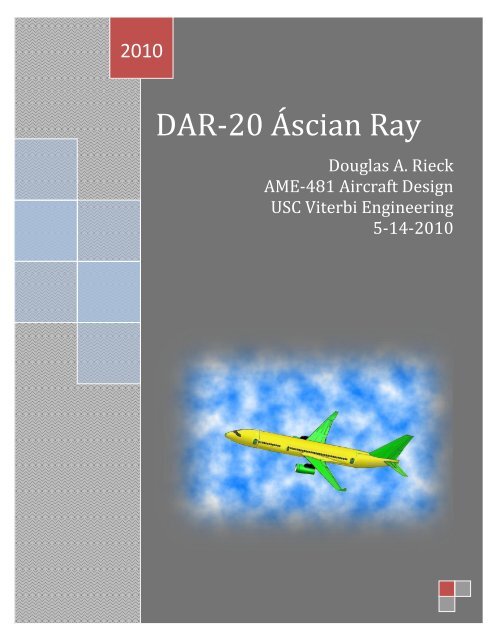
2010<br />
DAR-20 Áscian Ray<br />
Douglas A. Rieck<br />
AME-481 Aircraft Design<br />
USC Viterbi Engineering<br />
5-14-2010
1.0 Mission Requirements Summary:<br />
The Âscian Ray was designed to fill the role of a 200 passenger, medium range,<br />
medium field length commercial airliner for introduction into the market in early<br />
2020. It has been optimized to minimize direct operating cost under the conditions<br />
and constraints tabulated below.<br />
Passenger Capacity Goal 200<br />
Limited Bulk Cargo 0 - 10000 lbs<br />
TOFL (at MTOGW, standard atmosphere) < 8,400 ft<br />
LFL (at max landing Weight, standard atmosphere)<br />
ROC @ ICA and Max Cruise Altitude > 300 fps<br />
Cruise Altitude Optimized for <strong>DOC</strong><br />
M cruise<br />
2.0 Aircraft Geometry, Performance & Weights Summary<br />
Lifting Surfaces Wing Horizontal Vertical Winglet<br />
Area (ft 2 ) 1,200 396 532 51.2<br />
Span (ft) 114.9 46.6 31 7<br />
AR (n.d.) 11.0 5.5 1.8 0.96<br />
<strong>Sweep</strong> (deg.) 28 35 40 35<br />
Taper Ratio (n.d.) 0.46 0.30 0.30 0.35<br />
Average t/c (n.d.) 0.10 0.09 0.09<br />
Dihedral (deg.) 4 3 75<br />
MAC (in.) 10.9 9.3 18.9<br />
General Shape<br />
Fuselage Length (in.) 1,960<br />
Total Length (in.) 2,068<br />
Diameter (in.) 198.0<br />
Nose Fineness Ratio (n.d.) 1.8<br />
Tail Fineness Ratio (n.d.) 3.1<br />
Weight<br />
OEW 87110 lb<br />
MTOGW 160585 lb<br />
Mission Payload 43000 lb<br />
Bulk Cargo 5000 lb<br />
Design Mission Fuel 23877 lb<br />
Reserve Fuel 1601 lb<br />
Total Usable Fuel 25478 lb<br />
Optimized for <strong>DOC</strong><br />
Flight Conditions<br />
Field Elevation 0 ft<br />
Cruise Altitude 40000 ft<br />
Vc 774 ft/s<br />
0.8 -<br />
M c<br />
Cruise C L<br />
Cruise L / D<br />
0.66 -<br />
16.2 -<br />
Performance<br />
TOFL 8159<br />
LFL 4797<br />
Min ROC @ Crz 398<br />
Vldg Max<br />
138<br />
Vs1 164 kts<br />
Range 3000 nm<br />
P a g e | 2
TOFL (ft)<br />
14,000<br />
12,000<br />
10,000<br />
8,000<br />
6,000<br />
4,000<br />
2,000<br />
Below is a chart depicting FAA Required Runway Length for the Ascian Ray in standard<br />
atmosphere conditions at various altitudes and weight ranging from OEW to MTOGW.<br />
Takeoff Runway Length Requirements<br />
85,000 95,000 105,000 115,000 125,000 135,000 145,000 155,000 165,000<br />
TOGW (lbs)<br />
It can be seen that field length falls just under the 8,400 ft maximum length requirement<br />
(see table above). Only departure from higher altitude airports will result in a higher<br />
TOFL.<br />
P a g e | 3
Payload (lbs)<br />
3.0 Comparison to Competition<br />
80000<br />
70000<br />
60000<br />
50000<br />
40000<br />
30000<br />
20000<br />
10000<br />
The Ascian Ray’s payload capabilities may be marginally lower than the 737 for shorter mission<br />
distances, it makes up for it. For all ranges approximately greater than the design range (3,000<br />
nm) the Ascian Ray has a higher payload capability than the 737.<br />
TOGW/(PaxNmi) Lbs/PaxNmi<br />
0<br />
1.400<br />
1.200<br />
1.000<br />
0.800<br />
0.600<br />
0.400<br />
0.200<br />
0.000<br />
Competing Aircraft Payload-Range Comparison<br />
0 1000 2000 3000 4000 5000 6000 7000 8000 9000<br />
Range (nm)<br />
Commercial Transport, TOGW per passenger mile<br />
Historical Trends 2001/02 AWST Data<br />
1st Generation, Narrow Body TurboJets<br />
Narrow Body Turbofans<br />
Wide Body Turbofans<br />
Supersonic Concorde M=2.0<br />
Âscian Ray<br />
0 2,000 4,000 6,000 8,000 10,000 12,000<br />
Still Air Range (nmi)<br />
Âscian Ray<br />
Max Full Occupancy Range<br />
737-900ER w/ winglets<br />
737-700<br />
767-200<br />
MD-90-30/-30ER<br />
757-200<br />
The Ascian Ray also far outperforms other medium range airliners in weight efficiency.<br />
P a g e | 4
4.0 Configuration Description & Justification<br />
The Acian Ray is a turbofan powered monoplane with wing mounted engines and a<br />
conventional aft tail. The fuselage and wing structures take advantage of recent advances in<br />
composite materials which reduces aircraft’s weight without sacrificing payload. The Ascian<br />
Ray’s low MTOGW benefits L/D efficiency during flight and results in a lower cruise thrust<br />
required. This translates to a reduced engine weight and size, further improving fuel<br />
economy.<br />
Two high bypass ratio turbofans are mounted to the rear edge of the wing struts slightly<br />
inboard of the engine nacelles, each offering 32,000 lbs of SLST. The wings themselves are<br />
swept aft at 28 degrees, to minimize structural weight, while still offering superior cruise<br />
drag performance. The control surfaces on each wing consist of one inboard and one<br />
outboard aileron, running 30% of the chord. High CL is achieved with one inboard and one<br />
outboard single segment flap, and leading edge slats, also running 30% of the chord.<br />
The vertical stabilizer takes advantage of a low mounted, double-hinged rudder to provide<br />
sufficient yaw control for engine-out situations. The horizontal stabilizer is mounted further<br />
aft to provide clearance from the vertical stabilizer’s structural spar and to avoid negatives<br />
due to drag divergence. Both the horizontal and the vertical stabilizer are swept further<br />
than the wing to reduce drag and prevent control reversal during high Mach dive situations.<br />
The aircraft interior is divided into coach and business class, and offers a maximum capacity<br />
of 209 passengers. The business class section takes advantage of a slightly unorthodox 2 by<br />
2 by 1 seating arrangement to avoid wasted space while still adhering to aisle width<br />
guidelines. Coach seating features a 2 by 3 by 2 seating arrangement with two aisles for<br />
efficient navigation of the cabin by the potential 7 person crew. A twin aisle arrangement<br />
also provides for more efficient emergency egress through the six exit doors. Two 42’’x72’’<br />
exits are located at the forward galley and an additional two are located at the aft galley.<br />
Ahead of the wings are two supplementary 24”x54” exits.<br />
The nose of the plane was designed to elevate the pilots to a position where they have<br />
sufficient viewing angles according to Mil-Std 850 guidelines for transport and cargo<br />
aircraft. This is accomplished with a 10” step up to the cockpit floor level.<br />
P a g e | 5
P a g e | 6
5.0 Trade Studies<br />
Cost/ton-nm ($)<br />
TOGW (lbs)<br />
0.600<br />
0.580<br />
0.560<br />
0.540<br />
0.520<br />
0.500<br />
155,000<br />
152,500<br />
150,000<br />
147,500<br />
145,000<br />
142,500<br />
140,000<br />
<strong>DOC</strong> <strong>vs</strong>. Aspect Ratio<br />
8 10 12 14 16 18<br />
TOGW <strong>vs</strong>. Aspect Ratio<br />
8 10 12 14 16 18<br />
AR<br />
AR<br />
TOFL limit<br />
Design Point<br />
TOFL limit<br />
Design Point<br />
P a g e | 7
Cost/ton-nm ($)<br />
TOGW (lbs)<br />
0.700<br />
0.675<br />
0.650<br />
0.625<br />
0.600<br />
0.575<br />
0.550<br />
0.525<br />
0.500<br />
150,000<br />
148,000<br />
146,000<br />
144,000<br />
142,000<br />
140,000<br />
TOFL limit<br />
ROC limit<br />
Design Point<br />
6 8 10<br />
BPR<br />
12 14<br />
TOFL limit<br />
TOGW <strong>vs</strong>. Bypass Ratio<br />
Design Point<br />
<strong>DOC</strong> <strong>vs</strong>. BPR<br />
6 8 10 12 14<br />
BPR<br />
P a g e | 8
Cost/ton-nm ($)<br />
TOGW (lbs)<br />
0.6500<br />
0.6250<br />
0.6000<br />
0.5750<br />
0.5500<br />
0.5250<br />
0.5000<br />
154,000<br />
152,000<br />
150,000<br />
148,000<br />
146,000<br />
144,000<br />
142,000<br />
140,000<br />
<strong>DOC</strong> <strong>vs</strong>. <strong>Sweep</strong><br />
Cruise Buffet<br />
Buffet @ ICA<br />
TOFL limit<br />
ROC limit<br />
Design Point<br />
10 15 20 25 30<br />
<strong>Sweep</strong> (deg.)<br />
35 40 45 50<br />
TOGW <strong>vs</strong>. <strong>Sweep</strong><br />
10 20 30 40 50<br />
<strong>Sweep</strong> (deg.)<br />
Cruise Buffet<br />
Buffet @ ICA<br />
TOFL limit<br />
ROC limit<br />
Design Point<br />
P a g e | 9
This diagram demonstrates optimal sizing for the wing surface area and aspect ratio. The<br />
final wing geometry was selected based upon this plot in conjunction with a number of<br />
constraints, such as those in the previous charts.<br />
Cost/ton-nm ($)<br />
0.600<br />
0.590<br />
0.580<br />
0.570<br />
0.560<br />
0.550<br />
0.540<br />
0.530<br />
0.520<br />
800<br />
900<br />
1000<br />
<strong>DOC</strong> <strong>vs</strong> AR & Wing Area<br />
1100<br />
1200<br />
1300<br />
8<br />
10<br />
12<br />
14<br />
16<br />
18<br />
This snapshot of Jetsizer’s<br />
Mission input page (left) shows<br />
the results of the code and<br />
includes checks for mission<br />
constraints<br />
The image shown shows the<br />
results of an aircraft planform<br />
that was run with intentionally<br />
poor configuration in order to<br />
demonstrate the constraint<br />
checks.<br />
Note: The Ascian Ray PASSED<br />
these checks.<br />
P a g e | 10
C_L Buffet<br />
L/D<br />
18.000<br />
16.000<br />
14.000<br />
12.000<br />
10.000<br />
8.000<br />
6.000<br />
1.40<br />
1.20<br />
1.00<br />
0.80<br />
0.60<br />
0.40<br />
0.20<br />
0.00<br />
L/D <strong>vs</strong>. C_L<br />
0.2 0.3 0.4 0.5 0.6 0.7 0.8 0.9 1.0 1.1 1.2<br />
C_L Buffet <strong>vs</strong>. Mach<br />
0.200 0.300 0.400 0.500 0.600 0.700 0.800 0.900<br />
C_L<br />
Mach<br />
Crz<br />
C_L Buffet<br />
P a g e | 11
6.0 Stability & Control<br />
7.0 Cross-Section Drawing<br />
\<br />
Tail Geometry Horizontal Vertical<br />
Volume Ratio 1.80 0.23<br />
AR 5.5 1.8<br />
<strong>Sweep</strong> (deg.) 5.5 1.8<br />
t/c 0.09 0.09<br />
Moment Arm (in.) 850.0 743.00<br />
P a g e | 12
8.0 Interior Arrangement Diagram<br />
P a g e | 13
9.0 Cockpit Three-View Drawing<br />
P a g e | 14
10.0 Jetsizer Configuration Page<br />
Configuration Layout Image Control<br />
481 Spring 2010<br />
Douglas Rieck 0<br />
Ascian Ray < Notes<br />
< Notes<br />
Plan View<br />
Side View<br />
Front View<br />
Isometric View<br />
Change Red Cells<br />
Wing & Tails Wing Horiz. Vertical Winglet<br />
Wing Area | Tail Volume Ratio, VH | VV = 1,200 1.80 0.236 NA n.d.<br />
Axial Tail Pos'n (Xc/4-Xblkhd) = NA 120 140 NA in.<br />
Aspect Ratio, AR | Winglet Height = 11.00 5.50 1.80 7.0 n.d.<br />
<strong>Sweep</strong> Angle, c/4 = 28.00 35.00 40.00 35 deg<br />
Planform Break Pos'n Ybreak/(b/2) = 0.4 0.00 0.00 NA n.d.<br />
Break Taper Ratio Cbreak/Croot = NA 1.00 1.00 NA n.d.<br />
Tip Taper Ratio, Ctip/Croot = 0.46 0.30 0.30 0.35 n.d.<br />
Glove Extension at SOB, C/CSOB = 0.1 NA NA NA n.d.<br />
Yehudi Extension at SOB, C/CSOB = 0.35 NA NA NA n.d.<br />
Flap Chord Fraction Cflap/Cw = 0.25 0.35 0.35 NA n.d.<br />
Area, total trapezoidal, S = 1,200 396 532 140<br />
Span, b = 114.89 47 31 2<br />
Wing Dihedral Angle, = 4 3.00 NA 75 deg<br />
Vertical Offset, Z = -70 40.00 75.00 NA in.<br />
Airfoil t/c @ SOB = 0.115 NA NA NA n.d.<br />
Airfoil t/c @ Break = 0.100 0.09 0.09 NA n.d.<br />
Airfoil t/c @ Tip = 0.085 NA NA NA n.d.<br />
MAC Incidence Angle = 2.00 -1.00 NA NA deg<br />
Axial Wing pos'n, Xc/4trap@C/L = 880.0 NA NA NA in.<br />
1000<br />
800<br />
600<br />
400<br />
200<br />
0<br />
-200<br />
-400<br />
-600<br />
-800<br />
P a g e | 15
11.0 General Arrangement Drawing<br />
P a g e | 16
12.0 Aircraft Systems Drawing<br />
P a g e | 17