- Page 2 and 3: Nuke 101 Professional Compositing a
- Page 4 and 5: “I don’t always like writing, b
- Page 6 and 7: CoNTENTS v Adjusting properties, kn
- Page 8 and 9: CoNTENTS vii ChaPTER 8: Compositing
- Page 10 and 11: INTRODUCTION The Foundry’s Nuke i
- Page 12 and 13: INTRoDUCTIoN xi necessary. once a c
- Page 14 and 15: INTRoDUCTIoN xiii ADDiTioNAL TechNi
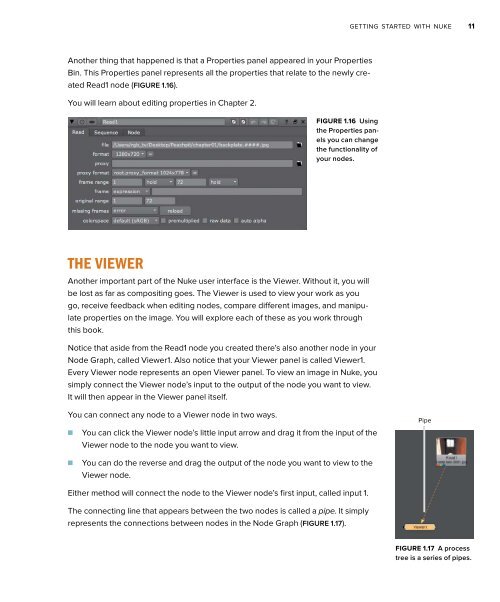
- Page 16 and 17: Throughout this title you will see
- Page 18 and 19: 1 eETTING STARTED wITh NUkE Nuke us
- Page 20 and 21: GETTING STARTED WITH NUKE 3 (Direct
- Page 22 and 23: GETTING STARTED WITH NUKE 5 FIGURE
- Page 24 and 25: GETTING STARTED WITH NUKE 7 Keyboar
- Page 26 and 27: GETTING STARTED WITH NUKE 9 The Rea
- Page 30 and 31: GETTING STARTED WITH NUKE 13 TaBLE
- Page 32 and 33: GETTING STARTED WITH NUKE 15 3. Hov
- Page 34 and 35: GETTING STARTED WITH NUKE 17 2. You
- Page 36 and 37: 2 TOURING ThE INTERFACE wITh A BASI
- Page 38 and 39: ToURING THE INTERFACE WITH A BASIC
- Page 40 and 41: ToURING THE INTERFACE WITH A BASIC
- Page 42 and 43: ToURING THE INTERFACE WITH A BASIC
- Page 44 and 45: ToURING THE INTERFACE WITH A BASIC
- Page 46 and 47: ToURING THE INTERFACE WITH A BASIC
- Page 48 and 49: ToURING THE INTERFACE WITH A BASIC
- Page 50 and 51: ToURING THE INTERFACE WITH A BASIC
- Page 52 and 53: ToURING THE INTERFACE WITH A BASIC
- Page 54 and 55: ToURING THE INTERFACE WITH A BASIC
- Page 56 and 57: ToURING THE INTERFACE WITH A BASIC
- Page 58 and 59: ToURING THE INTERFACE WITH A BASIC
- Page 60 and 61: ToURING THE INTERFACE WITH A BASIC
- Page 62 and 63: ToURING THE INTERFACE WITH A BASIC
- Page 64 and 65: ToURING THE INTERFACE WITH A BASIC
- Page 66 and 67: ToURING THE INTERFACE WITH A BASIC
- Page 68 and 69: ToURING THE INTERFACE WITH A BASIC
- Page 70 and 71: ToURING THE INTERFACE WITH A BASIC
- Page 72 and 73: ToURING THE INTERFACE WITH A BASIC
- Page 74 and 75: ToURING THE INTERFACE WITH A BASIC
- Page 76 and 77: ToURING THE INTERFACE WITH A BASIC
- Page 78 and 79:
3 COMPOSITING CGI wITh BIGGER NODE
- Page 80 and 81:
CoMPoSITING CGI WITH BIGGER NoDE TR
- Page 82 and 83:
CoMPoSITING CGI WITH BIGGER NoDE TR
- Page 84 and 85:
CoMPoSITING CGI WITH BIGGER NoDE TR
- Page 86 and 87:
CoMPoSITING CGI WITH BIGGER NoDE TR
- Page 88 and 89:
CoMPoSITING CGI WITH BIGGER NoDE TR
- Page 90 and 91:
CoMPoSITING CGI WITH BIGGER NoDE TR
- Page 92 and 93:
CoMPoSITING CGI WITH BIGGER NoDE TR
- Page 94 and 95:
CoMPoSITING CGI WITH BIGGER NoDE TR
- Page 96 and 97:
CoMPoSITING CGI WITH BIGGER NoDE TR
- Page 98 and 99:
CoMPoSITING CGI WITH BIGGER NoDE TR
- Page 100 and 101:
CoMPoSITING CGI WITH BIGGER NoDE TR
- Page 102 and 103:
CoMPoSITING CGI WITH BIGGER NoDE TR
- Page 104 and 105:
CoMPoSITING CGI WITH BIGGER NoDE TR
- Page 106 and 107:
CoMPoSITING CGI WITH BIGGER NoDE TR
- Page 108 and 109:
CoMPoSITING CGI WITH BIGGER NoDE TR
- Page 110 and 111:
CoMPoSITING CGI WITH BIGGER NoDE TR
- Page 112 and 113:
CoMPoSITING CGI WITH BIGGER NoDE TR
- Page 114 and 115:
4 COLOR CORRECTION Wow. This is a b
- Page 116 and 117:
CoLoR CoRRECTIoN 99 real-world beha
- Page 118 and 119:
CoLoR CoRRECTIoN 101 1. Launch Nuke
- Page 120 and 121:
CoLoR CoRRECTIoN 103 FIGURE 4.4 The
- Page 122 and 123:
CoLoR CoRRECTIoN 105 To wrap up thi
- Page 124 and 125:
CoLoR CoRRECTIoN 107 FIGURE 4.9 The
- Page 126 and 127:
CoLoR CoRRECTIoN 109 The Gamma oper
- Page 128 and 129:
CoLoR CoRRECTIoN 111 cReATiNg cuRVe
- Page 130 and 131:
CoLoR CoRRECTIoN 113 coLoR mATchiNg
- Page 132 and 133:
CoLoR CoRRECTIoN 115 9. View Merge1
- Page 134 and 135:
CoLoR CoRRECTIoN 117 The problem ha
- Page 136 and 137:
CoLoR CoRRECTIoN 119 7. Change Cons
- Page 138 and 139:
CoLoR CoRRECTIoN 121 The foreground
- Page 140 and 141:
CoLoR CoRRECTIoN 123 FIGURE 4.37 Th
- Page 142 and 143:
CoLoR CoRRECTIoN 125 FIGURE 4.41 No
- Page 144 and 145:
CoLoR CoRRECTIoN 127 FIGURE 4.43 Co
- Page 146 and 147:
CoLoR CoRRECTIoN 129 FIGURE 4.47 Th
- Page 148 and 149:
CoLoR CoRRECTIoN 131 24. To color c
- Page 150 and 151:
CoLoR CoRRECTIoN 133 FIGURE 4.55 Us
- Page 152 and 153:
5 2D TRACkING This chapter explains
- Page 154 and 155:
2D TRACKING 137 To track, you need
- Page 156 and 157:
2D TRACKING 139 the tracking part o
- Page 158 and 159:
2D TRACKING 141 FIGURE 5.9 A new no
- Page 160 and 161:
2D TRACKING 143 TRAckiNg FouR poiNT
- Page 162 and 163:
2D TRACKING 145 FIGURE 5.15 Activat
- Page 164 and 165:
2D TRACKING 147 By default, Epsilon
- Page 166 and 167:
2D TRACKING 149 FIGURE 5.22 The edg
- Page 168 and 169:
2D TRACKING 151 9. Choose Edit Expr
- Page 170 and 171:
2D TRACKING 153 FIGURE 5.29 Adjusti
- Page 172 and 173:
2D TRACKING 155 The three propertie
- Page 174 and 175:
2D TRACKING 157 9. Bring the Multip
- Page 176 and 177:
6 ROTOPAINT Roto and paint are two
- Page 178 and 179:
RoToPAINT 161 In the Toolbar at lef
- Page 180 and 181:
RoToPAINT 163 FIGURE 6.6 Strokespec
- Page 182 and 183:
RoToPAINT 165 5. Select a stroke in
- Page 184 and 185:
RoToPAINT 167 TaBLE 6.3 Bézier Hot
- Page 186 and 187:
RoToPAINT 169 unchecking the Autoke
- Page 188 and 189:
RoToPAINT 171 2. Click the plus sig
- Page 190 and 191:
RoToPAINT 173 You can move around i
- Page 192 and 193:
RoToPAINT 175 In this shot, a wire
- Page 194 and 195:
RoToPAINT 177 To make it easy to pa
- Page 196 and 197:
RoToPAINT 179 FIGURE 6.38 i’m see
- Page 198 and 199:
RoToPAINT 181 You now need to creat
- Page 200 and 201:
RoToPAINT 183 22. While Premult1 is
- Page 202 and 203:
RoToPAINT 185 nombiNiNg pAiNT, RoTo
- Page 204 and 205:
RoToPAINT 187 FIGURE 6.56 My Bézie
- Page 206 and 207:
RoToPAINT 189 2. Rename the new fol
- Page 208 and 209:
RoToPAINT 191 tsiNg The Dope sheeT
- Page 210 and 211:
RoToPAINT 193 FIGURE 6.68 The list
- Page 212 and 213:
RoToPAINT 195 So you are starting t
- Page 214 and 215:
7 kEyING Keying is the process of c
- Page 216 and 217:
KEYING 199 iNTRoDuciNg Nuke’s key
- Page 218 and 219:
KEYING 201 ruekeyeR The HueKeyer is
- Page 220 and 221:
KEYING 203 FIGURE 7.10 Changing a p
- Page 222 and 223:
KEYING 205 6. Change the first prop
- Page 224 and 225:
KEYING 207 Finally you need to adju
- Page 226 and 227:
KEYING 209 19. While looking at you
- Page 228 and 229:
KEYING 211 FIGURE 7.24 Branching ou
- Page 230 and 231:
KEYING 213 FIGURE 7.28 The starting
- Page 232 and 233:
KEYING 215 FIGURE 7.32 Choosing out
- Page 234 and 235:
KEYING 217 Now what you have in fro
- Page 236 and 237:
KEYING 219 7. Click Invert1 and the
- Page 238 and 239:
KEYING 221 The resulting yellow lin
- Page 240 and 241:
KEYING 223 You now have a tree cons
- Page 242 and 243:
COMPOSITING hI-RES STEREO IMAGES 8
- Page 244 and 245:
CoMPoSITING HI-RES STEREo IMAGES 22
- Page 246 and 247:
CoMPoSITING HI-RES STEREo IMAGES 22
- Page 248 and 249:
CoMPoSITING HI-RES STEREo IMAGES 23
- Page 250 and 251:
CoMPoSITING HI-RES STEREo IMAGES 23
- Page 252 and 253:
CoMPoSITING HI-RES STEREo IMAGES 23
- Page 254 and 255:
CoMPoSITING HI-RES STEREo IMAGES 23
- Page 256 and 257:
CoMPoSITING HI-RES STEREo IMAGES 23
- Page 258 and 259:
CoMPoSITING HI-RES STEREo IMAGES 24
- Page 260 and 261:
CoMPoSITING HI-RES STEREo IMAGES 24
- Page 262 and 263:
CoMPoSITING HI-RES STEREo IMAGES 24
- Page 264 and 265:
CoMPoSITING HI-RES STEREo IMAGES 24
- Page 266 and 267:
CoMPoSITING HI-RES STEREo IMAGES 24
- Page 268 and 269:
CoMPoSITING HI-RES STEREo IMAGES 25
- Page 270 and 271:
CoMPoSITING HI-RES STEREo IMAGES 25
- Page 272 and 273:
CoMPoSITING HI-RES STEREo IMAGES 25
- Page 274 and 275:
ThE NUkE 3D ENGINE 9 One of the mos
- Page 276 and 277:
THE NUKE 3D ENGINE 259 You’ll fin
- Page 278 and 279:
THE NUKE 3D ENGINE 261 Navigating t
- Page 280 and 281:
THE NUKE 3D ENGINE 263 The circles
- Page 282 and 283:
THE NUKE 3D ENGINE 265 The camera a
- Page 284 and 285:
THE NUKE 3D ENGINE 267 In relation
- Page 286 and 287:
THE NUKE 3D ENGINE 269 6. Move the
- Page 288 and 289:
THE NUKE 3D ENGINE 271 FIGURE 9.21
- Page 290 and 291:
THE NUKE 3D ENGINE 273 FIGURE 9.26
- Page 292 and 293:
THE NUKE 3D ENGINE 275 Ctrl/Cmd-dra
- Page 294 and 295:
THE NUKE 3D ENGINE 277 20. Select R
- Page 296 and 297:
CAMERA TRACkING 10 Nuke 6.0v1 intro
- Page 298 and 299:
CAMERA TRACKING 281 3. Save the scr
- Page 300 and 301:
CAMERA TRACKING 283 FIGURE 10.5 The
- Page 302 and 303:
CAMERA TRACKING 285 n Camera Motion
- Page 304 and 305:
CAMERA TRACKING 287 CameraTrackerPo
- Page 306 and 307:
CAMERA TRACKING 289 5. In the new p
- Page 308 and 309:
CAMERA TRACKING 291 FIGURE 10.22 Se
- Page 310 and 311:
CAMERA TRACKING 293 3. Choose File
- Page 312 and 313:
CAMERA TRACKING 295 7. View Scanlin
- Page 314 and 315:
CAMERA TRACKING 297 3. Press the 1
- Page 316 and 317:
CAMERA TRACKING 299 instead of a si
- Page 318 and 319:
CAMERA TRACKING 301 As you can see
- Page 320 and 321:
CAMERA TRACKING 303 FIGURE 10.40 Us
- Page 322 and 323:
CAMERA PROjECTION 11 in this chapte
- Page 324 and 325:
CAMERA PRoJECTIoN 307 FIGURE 11.2 C
- Page 326 and 327:
CAMERA PRoJECTIoN 309 13. Import ch
- Page 328 and 329:
CAMERA PRoJECTIoN 311 FIGURE 11.9 i
- Page 330 and 331:
CAMERA PRoJECTIoN 313 FIGURE 11.12
- Page 332 and 333:
CAMERA PRoJECTIoN 315 TWeAkiNg The
- Page 334 and 335:
CAMERA PRoJECTIoN 317 FIGURE 11.17
- Page 336 and 337:
CAMERA PRoJECTIoN 319 FIGURE 11.19
- Page 338 and 339:
CAMERA PRoJECTIoN 321 geometry, you
- Page 340 and 341:
CAMERA PRoJECTIoN 323 composiTiNg o
- Page 342 and 343:
CAMERA PRoJECTIoN 325 Final adjustm
- Page 344 and 345:
CAMERA PRoJECTIoN 327 FIGURE 11.29
- Page 346 and 347:
CAMERA PRoJECTIoN 329 11. Repeat th
- Page 348 and 349:
CAMERA PRoJECTIoN 331 23. At the fa
- Page 350 and 351:
CAMERA PRoJECTIoN 333 6. While Cons
- Page 352 and 353:
CAMERA PRoJECTIoN 335 FIGURE 11.43
- Page 354 and 355:
CUSTOMIzING NUkE wITh GIzMOS 12 One
- Page 356 and 357:
CUSToMIZING NUKE WITH GIZMoS 339 Nu
- Page 358 and 359:
CUSToMIZING NUKE WITH GIZMoS 341 He
- Page 360 and 361:
CUSToMIZING NUKE WITH GIZMoS 343 FI
- Page 362 and 363:
CUSToMIZING NUKE WITH GIZMoS 345 Re
- Page 364 and 365:
CUSToMIZING NUKE WITH GIZMoS 347 25
- Page 366 and 367:
CUSToMIZING NUKE WITH GIZMoS 349 FI
- Page 368 and 369:
CUSToMIZING NUKE WITH GIZMoS 351 15
- Page 370 and 371:
CUSToMIZING NUKE WITH GIZMoS 353 FI
- Page 372 and 373:
CUSToMIZING NUKE WITH GIZMoS 355 be
- Page 374 and 375:
CUSToMIZING NUKE WITH GIZMoS 357 FI
- Page 376 and 377:
CUSToMIZING NUKE WITH GIZMoS 359 23
- Page 378 and 379:
CUSToMIZING NUKE WITH GIZMoS 361 Th
- Page 380 and 381:
CUSToMIZING NUKE WITH GIZMoS 363 FI
- Page 382 and 383:
CUSToMIZING NUKE WITH GIZMoS 365 2.
- Page 384 and 385:
I CUSTOMIzING NUkE wITh PyThON A lo
- Page 386 and 387:
CUSToMIZING NUKE WITH PYTHoN 369 Ta
- Page 388 and 389:
CUSToMIZING NUKE WITH PYTHoN 371 10
- Page 390 and 391:
CUSToMIZING NUKE WITH PYTHoN 373 Th
- Page 392 and 393:
CUSToMIZING NUKE WITH PYTHoN 375 27
- Page 394 and 395:
INDEx Numbers 2D compositing, insid
- Page 396 and 397:
INDEX 379 seeing over background, 2
- Page 398 and 399:
INDEX 381 premultiplied, 25-28 prev
- Page 400 and 401:
INDEX 383 Proxy files, renaming, 24
- Page 402 and 403:
INDEX 385 T TCL script, typing, 77.
- Page 404:
WHERE ARE THE LESSON FILES? Nuke 10