JPE - Sept09 - cover2-4.pmd - Pipes & Pipelines International ...
JPE - Sept09 - cover2-4.pmd - Pipes & Pipelines International ...
JPE - Sept09 - cover2-4.pmd - Pipes & Pipelines International ...

Create successful ePaper yourself
Turn your PDF publications into a flip-book with our unique Google optimized e-Paper software.
156<br />
Results<br />
J-based limit loads -<br />
dependence on applied load<br />
Analyses using the above stress-strain model enabled the Jintegral<br />
to be calculated as a function of the applied load<br />
along the crack front. The highest J values, which generally<br />
occurred at the middle of the crack front adjacent to the<br />
smaller of the two ligaments (below and above the flaw),<br />
were adopted.<br />
The Journal of Pipeline Engineering<br />
Pipe dimension<br />
s,<br />
mm<br />
Flaw<br />
dimension<br />
s,<br />
mm<br />
Outside<br />
diameter<br />
Wall<br />
thickne<br />
ss<br />
Height Length<br />
Ligame<br />
nt<br />
to<br />
ID<br />
Ligame<br />
nt<br />
OD<br />
E1BH3L50L1. 5M0<br />
400 20 3 50 1. 5 15.<br />
5<br />
E1BH3L50L3M0400 20 3 50 3 14<br />
E1BH3L50L14M0400 20 3 50 14 3<br />
E1BH3L50L6M0400 20 3 50 6 11<br />
E1BH3L50L9M0400 20 3 50 9 8<br />
E1BH6L50L3M0400 20 6 50 3 11<br />
E1BH6L50L11M0400 20 6 50 11 3<br />
E1BH9L50L3M0400 20 9 50 3 8<br />
E1BH6L50L6M0400 20 6 50 6 8<br />
E1BH6L50L1. 5M0<br />
400 20 6 50 1. 5 12.<br />
5<br />
E1BH3L25L3M0400 20 3 25 3 14<br />
E1BH3L100L3M0400 20 3 100 3 14<br />
E1BH3L200L3M0400 20 3 200 3 14<br />
E1BH3L250L3M0400 20 3 250 3 14<br />
Sample issue<br />
E1BH6L25L3M0400 20 6 25 3 11<br />
E1BH6L100L3M0400 20 6 100 3 11<br />
E1BH3L25L6M0400 20 3 25 6 11<br />
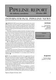
Table 1. Dimensions of pipe and flaw considered in finite-element analysis models (series E1).<br />
The J results were used to estimate the following J-based<br />
limit loads according to the approach described earlier:<br />
• M J2B E – consistent with Equn 2, representing the<br />
material-specific FAD of BS 7910 (Level 2B/3B)<br />
and R6 (Option 2) with J e estimated using the elastic<br />
pipe bending stress according to Equn 5.<br />
• M J2B EP – consistent with Equn 2, representing the<br />
material-specific FAD of BS 7910 (Level 2B/3B)<br />
and R6 (Option 2) with J e estimated using the<br />
elastic-plastic pipe bending stress in Equn 6.<br />
to