JPE - Sept09 - cover2-4.pmd - Pipes & Pipelines International ...
JPE - Sept09 - cover2-4.pmd - Pipes & Pipelines International ...
JPE - Sept09 - cover2-4.pmd - Pipes & Pipelines International ...

You also want an ePaper? Increase the reach of your titles
YUMPU automatically turns print PDFs into web optimized ePapers that Google loves.
186<br />
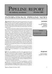
Y<br />
Rupture<br />
U<br />
circumferential direction is referred to as p y and the value<br />
of p y for this pipe material was found to be 38.4MPa<br />
(5560psi).<br />
First, the axial load test was undertaken on each specimen.<br />
The purpose was to simulate the initiation and growth of<br />
wrinkle for two scenarios: (i) assuming the first possibility<br />
that the wrinkle in the field linepipe may have formed and<br />
grew when the linepipe was in operation and then; (ii)<br />
assuming the other possibility, that is, the wrinkle may have<br />
initiated and grew when the linepipe was in shutdown<br />
condition. Accordingly, the internal pressure for Specimen<br />
1 was 0.25p y during the axial load test when the wrinkle<br />
formed and grew and no internal pressure was applied<br />
during the axial load test for Specimen 2 (Table 1).<br />
C<br />
Rupture<br />
Sample issue<br />
Specimen 2 Specimen 1 Field Specimen<br />
E<br />
The Journal of Pipeline Engineering<br />
Fig.3. Load-deformation behaviour.<br />
Fig.4. Final deformed shape of<br />
specimens.<br />
The load-deformation behaviours of both specimens are<br />
shown in Fig.3. The axial compression load was applied<br />
with small incremental loads at an eccentricity of 20mm to<br />
apply a moment along with the axial compression load on<br />
the specimens. As the axial load was increasing, the pipe<br />
specimens yielded (point Y in Fig.3) and then the axial load<br />
reached the maximum load carrying capacity of the pipe, as<br />
shown by point U in Fig.3. At this point, a wrinkle initiated<br />
at about the mid-height of the specimens. Application of<br />
axial load was then controlled by the displacement rather<br />
than the load. With the application of furt her axial<br />
deformation, the load-carrying capacity decreased as the<br />
wrinkle began to grow and became more asymmetric. The<br />
wrinkle at point C in Fig.3, closed from inside pipe wall and<br />
as a result, the load carrying capacity started to increase, as