CPT International 04/2017
The leading technical journal for the global foundry industry – Das führende Fachmagazin für die weltweite Gießerei-Industrie
The leading technical journal for the
global foundry industry – Das führende Fachmagazin für die
weltweite Gießerei-Industrie

Create successful ePaper yourself
Turn your PDF publications into a flip-book with our unique Google optimized e-Paper software.
PRESSURE DIE CASTING<br />
with conventional equipment could<br />
achieve,” Schlotterbeck points out.<br />
The desired target was a wall thickness<br />
of 0.15 mm. The main focus, however,<br />
was the question of how far one<br />
could approach this level with the<br />
conventional possibilities of a normal<br />
die-casting foundry. For this reason,<br />
a standard high-tech W80 Zn-RC<br />
hot-chamber machine was used for the<br />
casting experiments at the Frech Technical<br />
Center (Figure 2). This had the<br />
complete standard equipment without<br />
any special accessories. The alloy<br />
used for the experiments was commercially<br />
available ZL 5, and HF alloy was<br />
also used for comparative purposes. No<br />
vacuum support was used. Instead, a<br />
passive venting system with a double<br />
‘scrubbing board’ – made of steel and<br />
not CuBe – was selected. A 15-year-old<br />
modular training mold was used for<br />
the experiments, with wall thicknesses<br />
of 0.28 mm, 0.2 mm and 0.15 mm.<br />
With appropriate operation it was possible<br />
to achieve different wall thicknesses<br />
with this whilst also testing the<br />
effects of different casting channel and<br />
gating systems, cross-sections and ventilation.<br />
The mold’s tempering channels were<br />
designed according to conventional<br />
calculation rules. A heating/cooling<br />
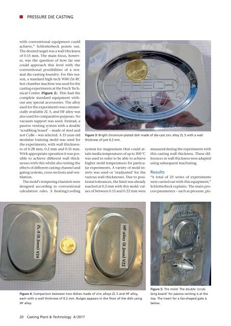
Figure 3: Bright chromium-plated dish made of die-cast zinc alloy ZL 5 with a wall<br />
thickness of just 0.2 mm.<br />
system for magnesium that could attain<br />
media temperatures of up to 300 °C<br />
was used in order to be able to achieve<br />
higher mold temperatures for particular<br />
experiments. A variety of mold inserts<br />
was used or ‘readjusted’ for the<br />
various wall thicknesses. Due to positional<br />
tolerances, the limit was already<br />
reached at 0.2 mm with this mold: values<br />
of between 0.13 and 0.22 mm were<br />
measured during the experiments with<br />
this casting wall thickness. These differences<br />
in wall thickness were adapted<br />
using subsequent machining.<br />
Results<br />
“A total of 25 series of experiments<br />
were carried out with this equipment,”<br />
Schlotterbeck explains. The main process<br />
parameters – such as pressure, pis-<br />
Figure 4: Comparison between two dishes made of zinc alloys ZL 5 and HF alloy,<br />
<br />
HF alloy<br />
Figure 5: The mold: The double ‘scrubbing<br />
board’ for passive venting is at the<br />
top. The insert for a fan-shaped gate is<br />
below.<br />
20 Casting Plant & Technology 4 / <strong>2017</strong>