5 FLIGHT TESTS NORTHEAST SAILPLANE PRODUCTS ...
5 FLIGHT TESTS NORTHEAST SAILPLANE PRODUCTS ...
5 FLIGHT TESTS NORTHEAST SAILPLANE PRODUCTS ...

You also want an ePaper? Increase the reach of your titles
YUMPU automatically turns print PDFs into web optimized ePapers that Google loves.
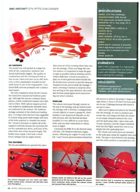
BME AIRCRAFT 27% PITTS CHALLENGER<br />
KIT CONTENTS<br />
The model was well packed in a large box<br />
with all the components, hardware and<br />
decals individually bagged. The quality of<br />
construction and the covering job were as<br />
nice as any I have ever seen on an ARF; however,<br />
a close examination revealed several<br />
small dents in one of the wing panels. I contacted<br />
BME and was promptly sent a replacement<br />
panel.<br />
My only complaints about the kit concern<br />
the instruction manual and hardware package.<br />
Although the manual contained many<br />
photos, certain construction phases were difficult<br />
to follow. BME's phone support proved<br />
very helpful in clarifying the assembly issues<br />
not addressed in the manual. The hardware<br />
package consisted of the wheels and landing<br />
gear, CA hinges (later kits have been upgraded<br />
to include hinge-point-style hinges) and most<br />
of the bolts required to complete the assembly.<br />
1 found it necessary to replace all of the<br />
supplied 4-40 bolts because the cap heads did<br />
not fit a standard-size driver, and some of the<br />
other bolts were of the incorrect length. The<br />
builder must supply a fuel tank, control<br />
horns, linkages and an engine mount.<br />
TAIL FEATHERS<br />
The fin and stabilizer are epoxied into place<br />
The aileron linkages are very short and tight.<br />
Du-Bro control horns, clevises and ball links were<br />
used throughout.<br />
after removal of the covering where they contact<br />
the fuselage. When you hinge the control<br />
surfaces, it's important to keep the gaps<br />
as tight as possible without limiting controlsurface<br />
deflection. I found it necessary to<br />
place an 1/8-inch-plywood shim beneath the<br />
aft elevator-servo mounts to provide adequate<br />
clearance for the servos inside the fuselage. I<br />
used a reversing Y-harness to keep the elevators<br />
moving in the same direction; this could<br />
also be done using digital servos and reversing<br />
one servo's rotation.<br />
FUSELAGE<br />
The cabane struts pass through cutouts on<br />
the top of the fuselage and are bolted inside<br />
the fuselage with 4-40 bolts. I enlarged these<br />
cutouts slightly to ensure a proper fit. Don't<br />
hesitate to use thread-lock liberally on the<br />
bolts because after the firewall has been<br />
installed, it's very difficult to access these<br />
bolts, and you don't want them to vibrate<br />
loose in flight!<br />
I mounted the BME 50 to the firewall using<br />
a Du-Bro 1.20 vibration-reduction engine<br />
mount. Offsetting the engine 3/l6 inch to the<br />
left, I used 1/8-inch-plywood shims behind the<br />
Cabane struts are bolted to the tab on the center<br />
plywood rib on the top wing. I wrapped the aileronservo<br />
extension wires around the cabane struts<br />
and secured them with zip-ties.<br />
SPECIFICATIONS<br />
MODEL- 27% Pitts Challenger<br />
MANUFACTURER: BME Aircraft<br />
TYPE: giant-scale aerobatic biplane<br />
WINGSPAN: 64 in. (top wing), 62 in.<br />
(bottom wing)<br />
TOTAL WING AREA: 1,420 sq. ft.<br />
LENGTH: 60 in.<br />
WEIGHT: 17 lb.<br />
WING LOADING: 27.6 oz./sq. ft.<br />
POWER REQ'D: 40 to 60cc gasoline<br />
engine<br />
RADIO REQ'D: minimum 4 channels<br />
with 6 high-torque servos for control<br />
surfaces and 1 standard servo for<br />
throttle<br />
PRICE: $499.99<br />
COMMENTS<br />
BME's Pitts Challenger is a high-quality,<br />
completely built-up balsa and plywood<br />
model with excellent fiberglass parts<br />
and matching film covering.<br />
HIGHLIGHTS<br />
>Finished appearance<br />
>Lightweight, built-up construction<br />
>Stable, aerobatic performance<br />
left mount to achieve the proper 3 degrees of<br />
right thrust. I chose a 33/4-inch Tru-Turn spin<br />
ner for my Challenger because this brand is<br />
second to none.<br />
After you've glued and pinned the firewall<br />
into the fuselage, it's easy to position and<br />
mount the cowl using 4-40 bolts. Be certain<br />
to cut ample clearance between the cowl<br />
and the spark-plug cable. I gave mine only<br />
1/4-inch clearance, and the engine vibration<br />
from the first flight caused the cowl to cut<br />
deeply into the spark-plug boot.<br />
The wheels and wheel pants are attached<br />
to the main gear using the supplied axles and<br />
bolts. The gear is then bolted to the fuselage,<br />
and the center portion is concealed by a cov-<br />
Each elevator half is actuated by independent<br />
servos; I used a Du-Bro pull-pull cable system on<br />
the rudder.