

tidu271

You also want an ePaper? Increase the reach of your titles
YUMPU automatically turns print PDFs into web optimized ePapers that Google loves.
Theory of Operation<br />
www.ti.com<br />
The RTD is generally installed in plastic, food, petrochemical-processing equipment, gas exhausts,<br />
pipelines, stoves, and other places in industry. The measurement circuit inside a control room can be<br />
hundreds of feet away from the processing plant. Under such conditions, the measurement wires that lead<br />
to the sensor can be several ohms. The small resistance of the wire could add to the RTD resistance.<br />
Therefore, errors in resistance measurement can be caused. For example, a wire resistance of 0.5 Ω in<br />
each lead of a field-mounted RTD causes an (0.5 Ω + 0.5 Ω) / (0.385°C/Ω) = 2.6°C error in measurement.<br />
RTDs are available in three different lead wire configurations: 2-wire, 3-wire, and 4-wire. Before discussing<br />
each configuration in detail, the background is given for a ratiometric measurement approach for RTDs, as<br />
this reference design also implements ratiometric measurement.<br />
5.2.3 Self-Heating<br />
Unlike thermocouples, RTDs are not self-powered. Therefore, RTD's need an excitation source. Excitation<br />
current flowing through the RTD produces a useful voltage that can be measured. Maximizing the<br />
excitation current appears desirable by augmenting system performance. The excitation current must be<br />
high enough so that voltage produced is greater than the peak-to-peak noise level of the ADC.<br />
At the same time, care must be taken not to pass a large current through the RTD, since a large current<br />
can cause higher I 2 R losses. I 2 R losses lead to self-heating within the element. If the sensor is unable to<br />
dissipate the self-heat, the sensing element increases above ambient temperature, which can cause<br />
resistance of the RTD element to increase. Therefore, an artificially high temperature will be reported.<br />
The errors due to self-heating cannot be easily corrected. These errors should be kept lower than 25% of<br />
the total error budget. The amount of self-heat generated also depends upon the sensor’s thermal<br />
resistance, surroundings, and placement in an application. An RTD placed in a moving, fluid medium will<br />
not self-heat because the moving fluid will keep the RTD at the temperature of the fluid.<br />
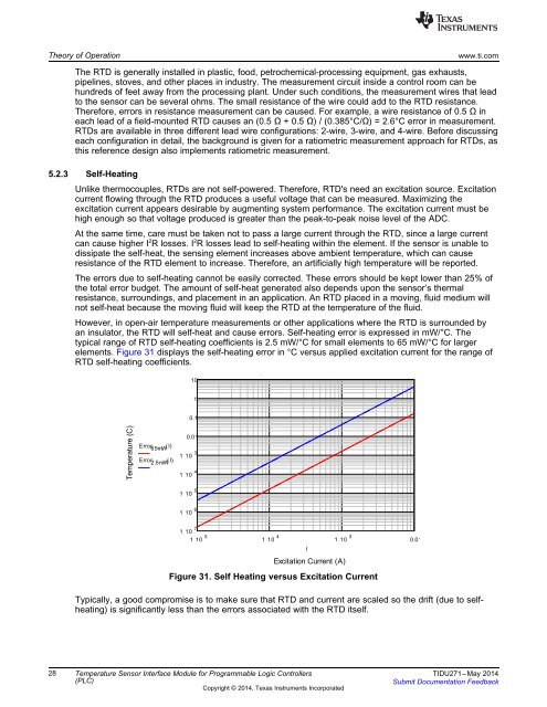
However, in open-air temperature measurements or other applications where the RTD is surrounded by<br />
an insulator, the RTD will self-heat and cause errors. Self-heating error is expressed in mW/°C. The<br />
typical range of RTD self-heating coefficients is 2.5 mW/°C for small elements to 65 mW/°C for larger<br />
elements. Figure 31 displays the self-heating error in °C versus applied excitation current for the range of<br />
RTD self-heating coefficients.<br />
10<br />
1<br />
0.1<br />
Temperature (C)<br />
Error 65mW<br />
( I)<br />
Error 2.5mW<br />
( I)<br />
0.01<br />
1 10 3<br />
1 10 4<br />
1 10 5<br />
1 10 6<br />
1 10 7<br />
1 10 5 1 10 4 1 10 3 0.01<br />
I<br />
Excitation Current (A)<br />
Figure 31. Self Heating versus Excitation Current<br />
Typically, a good compromise is to make sure that RTD and current are scaled so the drift (due to selfheating)<br />
is significantly less than the errors associated with the RTD itself.<br />
28 Temperature Sensor Interface Module for Programmable Logic Controllers TIDU271–May 2014<br />
(PLC)<br />
Submit Documentation Feedback<br />
Copyright © 2014, Texas Instruments Incorporated