

tidu271

You also want an ePaper? Increase the reach of your titles
YUMPU automatically turns print PDFs into web optimized ePapers that Google loves.
www.ti.com<br />
Theory of Operation<br />
The two-wire RTD measurement is least accurate with longer lead wires resistance. Two-wire RTD<br />
measurement variation with temperature adds significant measurement error. The two-wire RTD<br />
measurement is used only when the sensor is located at a very short distance. Higher accuracy is not a<br />
concern in this case of short distance. Otherwise (in the case of long distance), the effect of lead wires<br />
cannot be eliminated.<br />
5.2.6 Three-Wire RTD Application<br />
Line 3<br />
R BIAS<br />
REFOP<br />
REFON<br />
AVSS<br />
MUX<br />
IDAC<br />
Current<br />
RTD<br />
Line 2<br />
Line 1<br />
AIN0<br />
AIN1<br />
PGA<br />
1:128<br />
24-Bit<br />
ΔΣ ADC<br />
Digital<br />
Filter<br />
Serial<br />
Interface<br />
and<br />
Control<br />
SCLK<br />
DIN<br />
DOUT<br />
DRDY<br />
CS<br />
START<br />
RESET<br />
Line Resistance<br />
IDAC<br />
Current<br />
CLK<br />
A<br />
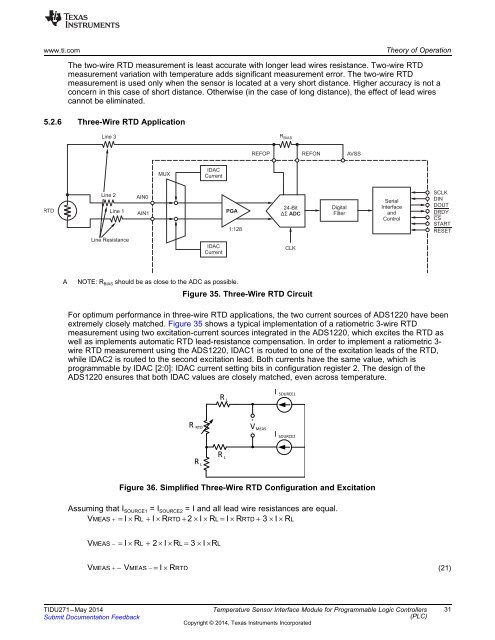
NOTE: R BIAS should be as close to the ADC as possible.<br />
Figure 35. Three-Wire RTD Circuit<br />
For optimum performance in three-wire RTD applications, the two current sources of ADS1220 have been<br />
extremely closely matched. Figure 35 shows a typical implementation of a ratiometric 3-wire RTD<br />
measurement using two excitation-current sources integrated in the ADS1220, which excites the RTD as<br />
well as implements automatic RTD lead-resistance compensation. In order to implement a ratiometric 3-<br />
wire RTD measurement using the ADS1220, IDAC1 is routed to one of the excitation leads of the RTD,<br />
while IDAC2 is routed to the second excitation lead. Both currents have the same value, which is<br />
programmable by IDAC [2:0]: IDAC current setting bits in configuration register 2. The design of the<br />
ADS1220 ensures that both IDAC values are closely matched, even across temperature.<br />
R L<br />
I<br />
SOURCE1<br />
R RTD<br />
V + MEAS<br />
-<br />
I<br />
SOURCE2<br />
R L<br />
R L<br />
Figure 36. Simplified Three-Wire RTD Configuration and Excitation<br />
Assuming that I SOURCE1 = I SOURCE2 = I and all lead wire resistances are equal.<br />
VMEAS I RL I RRTD 2 I RL I RRTD 3 I RL<br />
V I R 2 I R 3 I R<br />
MEAS L L L<br />
V V I R<br />
MEAS MEAS RTD<br />
(21)<br />
TIDU271–May 2014<br />
Submit Documentation Feedback<br />
Temperature Sensor Interface Module for Programmable Logic Controllers<br />
(PLC)<br />
Copyright © 2014, Texas Instruments Incorporated<br />
31