


Create successful ePaper yourself
Turn your PDF publications into a flip-book with our unique Google optimized e-Paper software.
CYLINDER<br />
HEAD<br />
The cylinder head must be removed if it is necessary<br />
to regrind valves, or to work on the piston, rings or<br />
connecting rods. All of the cylinder head screws are<br />
plainly in view and can be easily removed. Screws of<br />
different lengths are used but these can be properly<br />
reassembled according to the various lengths of<br />
cylinder head bosses.<br />
In reassembly; remove all carbon and lead deposits<br />
from combustion chamber. It is recommended that new<br />
cylinder head gaskets be used as the old gaskets will<br />
be compressed and hard and may not seal properly.<br />
Use a mixture of graphite and oil on the cylinder head<br />
screws to prevent them from rusting tight against the<br />
cylinder block. Tighten cylinder head screws to 24<br />
ft. Ibs. torque in the sequence shown in Fig. 21.<br />
After complete assembly and engine is run in, retorque<br />
head screws.<br />
Fig. 19<br />
15 14 13 21<br />
12<br />
F ig. 20<br />
1<br />
22 ~<br />
ing the flywheel shroud to the lower cylinder shrouds<br />
and cylinder heat deflectors, then remove the screws<br />
holding the flywheel shroud to gear cover.<br />
On power units, remove the front end panel together<br />
with flywheel shroud. Remove the rear end panel<br />
complete with fuel tank. Balance of shrouding can<br />
now be readily removed.<br />
In Reassembly; use the thin head capscrews~ for<br />
mounting the flywheel shroud, in the two holes close<br />
to the horizontal centerline. This is for stntor clearance<br />
on engines with flywheel alternator.<br />
FUEL TANK<br />
If a side mount fuel tank is used, disconnect fuel<br />
line and remove tank assembly as illustrated in<br />
Fig. 20.<br />
CARBURETOR AND MANIFOLD<br />
The carburetor and manifold can be removed as a<br />
complete unit. In reassemhly; tighten the manifold<br />
nuts to |8 ft. lbs. torque. Tightening beyond specifications<br />
may cause the flanges to break.<br />
GEAR COVER<br />
6 7 8<br />
F ig. 21<br />
Disconnect the governor linkage and remove governor<br />
housing and gear-flyweight assembly from shaft in<br />
gear cover. Take out the ten gear cover capscrews<br />
and drive out the two dowel pins as shown in Fig. 23.<br />
The cover can then be taken off - exposing the gear<br />
train as illustrated in Fig. 24.<br />
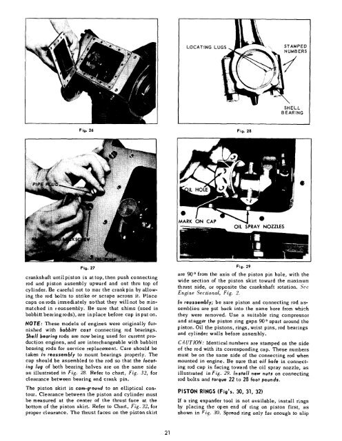
19