


Create successful ePaper yourself
Turn your PDF publications into a flip-book with our unique Google optimized e-Paper software.
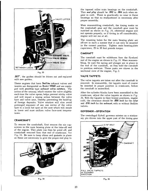
LOCATING LUGS<br />
STAMPED<br />
NUMBERS<br />
SHELL<br />
BEARING<br />
Fig. 26 Fig. 28<br />
MARK ON CAP<br />
OIL SPRAY NOZZLES<br />
Fig, 27<br />
crankshaft untilpiston is at top, then push connecting<br />
rod and piston assembly upward and out thru top of<br />
cylinder. Be careful not to mar the crank pin by allowing<br />
the rod bolts to strike or scrape across it. Place<br />
caps on rods immediately so that they willnot be mismatched<br />
in reassembly. Be sure that shims (used in<br />
babbitt bearing rods), are in place before cap is put on.<br />
NOTE: These models of engines were originally furnished<br />
with babbitt cast connecting rod bearings.<br />
Shell bearing rods are now being used for current production<br />
engines, and are interchangeable with babbitt<br />
bearing rods for service replacement. Care should be<br />
taken in reassembly to mount bearings properly. The<br />
cap should be assembled to the rod so that the local.<br />
ing lug of both bearing halves are on the same side<br />
as illustrated in Fig. 28. Refer to chart, Fig. 32, for<br />
clearance between bearing and crank pin.<br />
The piston skirt is cam-ground to an elliptical contour.<br />
Clearance between the piston and cylinder must<br />
be measured at the center of the thrust face at the<br />
bottom of the piston skirt. Refer to Chart, Fig. 32, for<br />
proper clearance. The thrust faces on the piston skirt<br />
Fig. 29<br />
are 90° from the axis of the piston pin hole, with the<br />
wide section of the piston skirt toward the maximum<br />
thrust side, or opposite the crankshaft rotation, See<br />
<strong>Engine</strong> Sectional, Fig. 2.<br />
In reossembly; be sure piston and connecting rod assemblies<br />
are put back into the same bore from which<br />
they were removed. Use a suitable ring compressor<br />
and stagger the piston ring gaps 90 ° apart around the<br />
piston. Oil the pistons, rings, wrist pins, rod bearings<br />
and cylinder walls before assembly.<br />
CAUTION: Identical numbers are stamped on the side<br />
of the rod with its corresponding cap. These numbers<br />
must be on the same side of the connecting rod when<br />
mounted in engine. Be sure that oil hole in connectiag<br />
rod cap is facing toward the oii spray nozzle, as<br />
illustrated in Fig. 29. Install new nuts on connecting<br />
rod bolts and torque 22 to 28 foot pounds.<br />
PISTON RINGS (Fig’s. 30, 31, 32)<br />
If a ring expander tool is not available, install rings<br />
by placing the open end of ring on piston first, as<br />
shown in Fig. 30. Spread ring only far enough to slip<br />
21