Processing of Primary Fischer-Tropsch Products - University of Alberta
Processing of Primary Fischer-Tropsch Products - University of Alberta
Processing of Primary Fischer-Tropsch Products - University of Alberta

Create successful ePaper yourself
Turn your PDF publications into a flip-book with our unique Google optimized e-Paper software.
Studies in Surface Science and Catalysis 152<br />
A. Steynberg and M. Dry (Editors)<br />
9 2004 Elsevier B.V. All rights reserved.<br />
Chapter 6<br />
<strong>Processing</strong> <strong>of</strong> <strong>Primary</strong> <strong>Fischer</strong>-<strong>Tropsch</strong> <strong>Products</strong><br />
L. P. Dancuart, R. de Haan and A. de Klerk<br />
Sasol Technology R&D<br />
P.O. Box 1, Sasolburg, 1947, South Africa<br />
1. INTRODUCTION<br />
The refining <strong>of</strong> <strong>Fischer</strong>-<strong>Tropsch</strong> (FT) products is very different from crude oil<br />
refining in terms <strong>of</strong> feed composition, refining focus and heat management [1 ].<br />
Despite these differences, the refining <strong>of</strong> FT products is not widespread enough<br />
to have attracted FT specific refining technologies. The same basic technologies<br />
and commercial catalysts used in crude oil refining [2] have therefore been<br />
adapted for use in FT primary product refining.<br />
The refinery configuration and choice <strong>of</strong> refining technologies depend<br />
largely on the split between chemicals and fuels production. Valuable products,<br />
like linear alpha-olefins, can be extracted from the FT product. The recovery (or<br />
non-recovery) <strong>of</strong> such chemicals would change the product slate and<br />
consequently the refining methodology. Historically the refining <strong>of</strong> FT products<br />
focused mainly on fuels. The evolution <strong>of</strong> FT refining is discussed with emphasis<br />
on the impact on the refinery design <strong>of</strong> changing fuel specifications;<br />
improvements in technology and the exploitation <strong>of</strong> chemical opportunities.<br />
As for a crude oil refinery, the FT refinery design depends on the nature <strong>of</strong><br />
the feed that must be processed. Some key properties <strong>of</strong> the primary FT product<br />
components are discussed with an explanation <strong>of</strong> their impact on the refining<br />
approach, most notably the hetero-atom constraints, compatibility with fuel<br />
requirements and carbon number distribution. This serves as an introduction to<br />
the detailed discussion on the preferred refining options for the various cuts. The<br />
focus is on fuels production from the primary product although some <strong>of</strong> the<br />
chemical extraction opportunities that exist are highlighted in this context.
Towards the end <strong>of</strong> this chapter some opportunities to target the large scale<br />
production <strong>of</strong> bulk commodity chemicals are presented.<br />
Some notes on refinery integration opportunities are provided and there are<br />
pointers to the design <strong>of</strong> future FT refineries.<br />
2. HISTORICAL PERSPECTIVE<br />
The original Sasol 1 production facility in Sasolburg had both Arge Low<br />
Temperature FT (LTFT) and Synthol High Temperature FT (HTFT) synthesis<br />
technology operating in parallel. The Synthol refinery produced mainly petrol<br />
(also termed gasoline or mogas, in other words, spark ignition engine fuel), while<br />
the Arge product refinery produced mainly heavier products, i.e. diesel<br />
(compression ignition engine fuel) and wax [3, 4, 5]. The HTFT plant in<br />
Brownsville, Texas (Hydrocol process) [6, 7] that preceded the Sasolburg facility<br />
also targeted petrol as the main fuel product. Fuel specifications in the 1950's<br />
were not very demanding and product upgrading was mainly by distillation,<br />
hydrogenation, clay treatment (to decrease the oxygenates and increase the<br />
aromatic contents) and oligomerisation <strong>of</strong> light olefins. Lead containing<br />
additives were used to increase octane as was common practice in oil refineries<br />
at that time.<br />
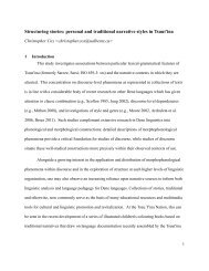
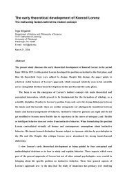
The Sasol production facilities in Secunda exclusively use HTFT<br />
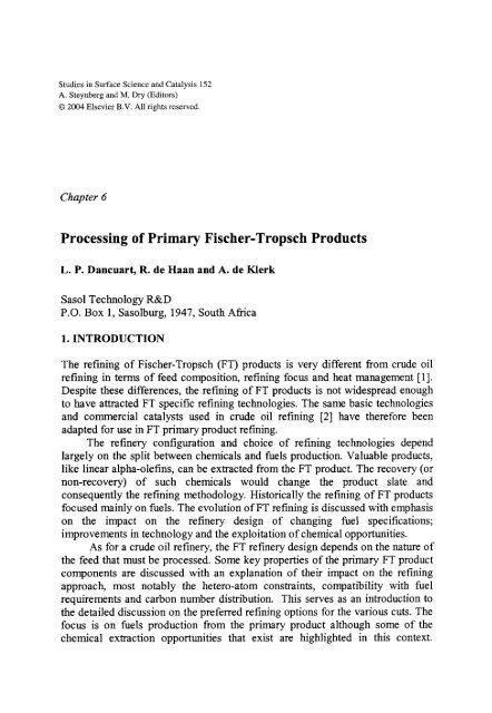
technology. Fuel specifications in the 1980's were still not very demanding and<br />
the FT product refineries were consequently <strong>of</strong> a straightforward design (Fig. 1)<br />
[8]. Since coal is used as feed material, the overall facility is a bit more<br />
complicated [9]. In addition to the FT refinery, a tar refinery is required to<br />
process the pyrolysis products from coal gasification (not shown in Fig. 1). Tar<br />
refining is linked to coal processing and is similar to the refining required during<br />
coke production for the metallurgical industry.<br />
The refinery designs not only reflected the prevailing fuel specifications,<br />
but also the fact that the HTFT refineries were seen as mainly fuels producers.<br />
The potential to extract chemicals was noted [10], but was not incorporated in<br />
the designs. The first change in this perspective started in the 1960's, with the<br />
announcement that ethylene from FT synthesis, and nitrogen from the air<br />
separation plant, would be recovered for the production <strong>of</strong> plastic and ammonia<br />
at the Sasol 1 facility [ 11 ].<br />
The separation <strong>of</strong> ethylene and propylene was incorporated in the later<br />
Secunda designs. This was taken a step further in the 1990's, with the recovery<br />
and purification <strong>of</strong> linear alpha-olefins as co-monomers for the polymer industry.<br />
Similarly, heavier alpha-olefins are now recovered and purified for detergent<br />
alcohol production via hydr<strong>of</strong>ormylation.<br />
483
484<br />
Cold<br />
separation .~~"~<br />
Condensate~<br />
Atmospheric<br />
<strong>Fischer</strong>- ~<br />
<strong>Tropsch</strong><br />
process Stabilised ] ] '<br />
Light Oil ~)<br />
Vacuum<br />
distillation<br />
l Decanted<br />
Oil<br />
Aqueous product<br />
Ethylene recovery<br />
Propylene recovery<br />
--~ Olefin oligomerisation I<br />
Naphtha hydrogenation ~ Naphtha reforming<br />
Distillate hydrogenation I<br />
t- Ethylene<br />
9<br />
Olefin hydrogenation<br />
[<br />
!<br />
r- Propylene<br />
9 LPG<br />
~ Unhydrogenated petrol<br />
t- Hydrogenated petrol<br />
t- Kerosene<br />
Olefinic petrol<br />
~- LPG<br />
Aromatic petrol<br />
:- Light diesel<br />
9 i.,,, [ ~- Petrol<br />
Distillate hydrocrack "e ! Heavy diesel<br />
Fuel oil<br />
;- Fuel oil<br />
..I I :- Oxygenate chemicals<br />
"1 Chemical work-up I ~ Water<br />
Figure 1 High Temperature <strong>Fischer</strong>-<strong>Tropsch</strong> refinery design originally used at Secunda<br />
<strong>Fischer</strong>-<br />
<strong>Tropsch</strong><br />
process<br />
Cold<br />
separation ._?<br />
Condensate~j<br />
A tm osph eric<br />
Stabilised I ~<br />
Light Oilvacuum ~_,<br />
oilDecanted ~<br />
Aqueous product<br />
~|<br />
[_~ Ethylene recovery [<br />
Propylene recovery [<br />
....<br />
--t Olefin oligomerisation [<br />
Alpha-olefin recovery ]<br />
~- Ethylene<br />
Propylene<br />
LPG<br />
9 [ ~- Unhydrogenated petrol<br />
Olefinhydrogenation ~- Hydrogenated petrol<br />
I ~- Kerosene<br />
( .....<br />
~j Isomerise, Etherification[~ :- Olefinic petrol<br />
e TAME<br />
~- Alpha-olefins<br />
Naphtha hydrogenation ]<br />
l ~<br />
.~1<br />
"1 Naphtha reforming<br />
I<br />
]<br />
LPG<br />
~- Aromatic petrol<br />
9 ] ttydr<strong>of</strong>ormylation I ~ Detergent alcohols<br />
~- Light diesel<br />
Distillate hydrogenation 9 ! ~- Petrol<br />
Distillate hydrocracking tleavy diesel<br />
I Fuel oil<br />
Fuel oil<br />
I I ~ Oxygenate chemicals<br />
"1 Chemical work-up ] ~- Water
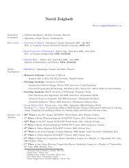
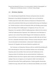
Figure 2 Current (2004) High Temperature <strong>Fischer</strong>-<strong>Tropsch</strong> refinery used at Secunda<br />
The HTFT reactors at Sasol 1 were decommissioned in the 1990's and the<br />
facility was converted to a chemicals production site. The Secunda plants also<br />
started to lose their identity as fuels-only refineries as more and more chemicals<br />
were targeted for extraction [12]. Yet, most <strong>of</strong> the production volume still went<br />
to fuels and with the more stringent fuel specifications, some fuels refining units<br />
were added, such as etherification and skeletal isomerisation (Fig. 2).<br />
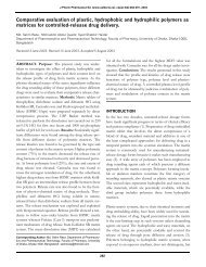
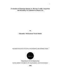
With the construction <strong>of</strong> the first commercial HTFT gas-to-liquids (GTL)<br />
plant, an all-fuels approach was again followed. The PetroSA GTL plant started<br />
operation in 1993 as Mossgas in Mossel Bay, South Africa. The plant is an<br />
integrated facility for natural gas processing that makes use <strong>of</strong> Sasol Synthol<br />
technology. The feed is obtained from their own natural gas fields located<br />
<strong>of</strong>fshore. The primary gas separation is done at the main production platform<br />
where Raw Natural Gas and Natural Gas Liquids (NGL) are produced and<br />
transported some 120 km to the GTL plant by pipelines. A secondary separation<br />
is done onshore where the natural gas composition is made compatible with the<br />
GTL process requirements and the NGL is separated into Liquefied Petroleum<br />
Gas (LPG), Naphtha and Diesel. The refinery design resembled that <strong>of</strong> the<br />
Secunda facilities, but some changes were made to the C2-C8 processing (Fig. 3)<br />
[13].<br />
Condensate<br />
Gas<br />
Natural<br />
Gas<br />
Liquids<br />
Recovery<br />
T"<br />
<strong>Fischer</strong>-<br />
<strong>Tropsch</strong><br />
process<br />
........................... ~ Skeletal isomerisation I 9<br />
iiiiii ! ili- ,I Alkylation ] ~ Alkylatepetrol<br />
Tail !i 9 LPG<br />
gas ! i _ _ ~ O lefin oligomerisation I 9 Unhydrogenated petrol<br />
llr<br />
i. ~ s keletal isom e ris a t ion [ I ~ Isomerate petrol<br />
i ~j Naphtha hydrogenation [<br />
Light [ S0111 "11 t ]i~i a b i l i s<br />
9 " "-i I<br />
..,<br />
"[ e Naphtha d ref~<br />
i -~ LPG<br />
-~ Aromatic petrol<br />
9 :_1 Distillate hydrogenation I -~ Kerosene<br />
Decanted k.U/ , "-~ A -~ Diesel<br />
Oil | '~ ...................................................................... i<br />
| L Fuel oil<br />
Aqueous product "l Chemical work-up [ -~'~ WaterOXygenate chemicals<br />
Figure 3 High Temperature <strong>Fischer</strong>-<strong>Tropsch</strong> refinery design <strong>of</strong> Mossgas (now PetroSA) at<br />
Mossel Bay<br />
485
486<br />
Chemical production at the Mossel Bay refinery is possible but lacks<br />
economy <strong>of</strong> scale relative to the Secunda plants. Although not implemented,<br />
some chemical production opportunities have been investigated [14]. Future<br />
HTFT plants are likely to target bulk commodity chemicals to decrease the<br />
reliance on high oil prices for satisfactory economic performance. Chemicals<br />
extraction is an attractive option to grow income [ 15] and this can be considered<br />
even after the FT plant is in operation provided the remaining plant life is<br />
sufficient. Since the Mossel Bay refinery uses natural gas as feed material and<br />
not coal, it does not have a tar refinery associated with it. However, the co-<br />
processing <strong>of</strong> natural gas <strong>of</strong>fers its own advantages.<br />
The historic evolution <strong>of</strong> the Sasol HTFT refineries was not only driven by<br />
technology advances and market requirements, but also by the strategic<br />
positioning <strong>of</strong> the company. Current thinking favours expansion in the field <strong>of</strong><br />
polymers and future changes may well have to balance the demands <strong>of</strong> more<br />
stringent fuel specifications with growth in ethylene and propylene production.<br />
To meet such an eventuality a change in the refinery configuration to include a<br />
Superflex TM Catalytic Cracker (SCC) unit is being implemented [ 16].<br />
3. UPGRADING OF HIGH TEMPERATURE FISCHER-TROPSCH<br />
(HTFT) PRODUCTS<br />
3.1 Influence <strong>of</strong> feed properties on refining approach<br />
To understand HTFT refining, it is necessary to take a closer look at the<br />
refinery feed material. Although the feed composition depends strongly on the<br />
nature <strong>of</strong> the FT catalyst and operating conditions [4, 5], a high temperature iron<br />
based FT primary product typically has the following attributes:<br />
9 The oil and aqueous products are essentially sulphur-free.<br />
9 The oil and aqueous products are low in nitrogen-containing compounds.<br />
9 The oil and aqueous products contain percentage levels <strong>of</strong> oxygenates<br />
(alcohols, acids, esters and carbonyls).<br />
9 The oil product is rich in olefinic material, especially linear alpha-olefins.<br />
9 The oil product is poor in aromatics and naphthenics (cyclo-paraffins and<br />
cyclo-olefins).<br />
9 The oil product is mostly linear or with a low degree <strong>of</strong> branching.<br />
9 The oil product follows a Schultz-Flory distribution, heavily weighted<br />
towards light hydrocarbons.<br />
9 The aqueous product contains most <strong>of</strong> the short chain oxygenates.<br />
The discussion presupposes that the products are typical HTFT products<br />
and have not been modified in some way by the addition <strong>of</strong> a second catalyst<br />
type. It may seem desirable to use a second catalyst type to make the HTFT
product more amenable to refining [17], but this train <strong>of</strong> thought will not be<br />
explored further.<br />
3.1.1 Hetero-atom constraints<br />
The most obvious advantage is the low sulphur content. There is no need to<br />
worry about deep hydrodesulphurisation or other sulphur reduction technologies<br />
to meet fuel sulphur specifications. There is also no need to worry about the<br />
sulphur sensitivity <strong>of</strong> catalysts and high activity tmsulphided catalysts can in<br />
principle be used for hydrotreating.<br />
The bugbear <strong>of</strong> a FT refinery is oxygenates and most refining processes are<br />
affected. Only the lighter than C5 boiling range material is oxygenate free or<br />
have oxygenates present in very low concentration. Oxygenates can therefore be<br />
considered critical in HTFT refining, with carboxylic acids being especially<br />
troublesome. They restrict the metallurgy <strong>of</strong> processing equipment and cause<br />
metal leaching <strong>of</strong> some classes <strong>of</strong> unsulphided catalysts, most notably nickel<br />
promoted catalysts. Furthermore, the carboxylic acids tend to be difficult to<br />
remove by hydrotreating.<br />
Unlike hydrodesulphurisation (HDS) and hydrodenitrogenation (HI)N) that<br />
produces hydrogen sulphide and ammonia, hydrodeoxygenation (HDO)<br />
produces water. This not only complicates product work-up, but also creates<br />
problems in catalysis. Hydrothermal dealumination can lead to changed catalyst<br />
behaviour [18] and faster catalyst deactivation [19]. In chlorided catalyst systems<br />
severe corrosion may also result from the presence <strong>of</strong> water.<br />
3.1.2 Petrol component properties<br />
It is instructive to look at the hydrocarbon component classes in relation to<br />
their octane value and abundance in FT products. As an example, the C7<br />
hydrocarbon compound classes have been listed, with their relative abundance<br />
on an oxygenate-free basis in a high temperature FT product (Table 1).<br />
It is clear that an unrefined HTFT product has a low octane and that the<br />
only saving grace is its high olefin content. Exploiting the high olefin content<br />
and redressing both the low degree <strong>of</strong> branching and low aromatics content, are<br />
therefore central to the fuels refining strategy. This can typically be done by<br />
skeletal isomerisation <strong>of</strong> the olefins [21, 22] (with the possibility for<br />
etherification), skeletal isomerisation <strong>of</strong> the paraffins [23, 24], selective<br />
aromatisation or reforming [25, 26, 27]. Similarly, the extraction <strong>of</strong> alpha-olefins<br />
as chemicals is desirable from a fuels point <strong>of</strong> view. In some cases it may also be<br />
useful to consider double bond isomerisation as a cheap way to improve the<br />
octane <strong>of</strong> alpha-olefin-rich material.<br />
487
488<br />
Table 1<br />
Research octane value (RON) and motor octane value (MON) <strong>of</strong> some C7 hydrocarbons [20]<br />
and their relative abundance in unrefined High Temperature <strong>Fischer</strong>-<strong>Tropsch</strong> product<br />
Class Compound RON MON HTFT abundance<br />
Linear paraffin n-Heptane 0.0 0.0 8<br />
Branched paraffin 3-Methylhexane 52.0 55.8 4<br />
2,3-Dimethylpentane 91.1 88.5<br />
2,2,3-Trimethylbutane 112.2 101.3<br />
Linear olefin 1-Heptene 54.5 50.7 50<br />
trans-2-Heptene 73.4 68.6<br />
Branched olefin 3-Methyl- 1-hexene 82.2 71.5 22<br />
trans-3-Methyl-2-hexene 91.5 79.6<br />
2,3-Dimethyl- 1-pentene 99.3 84.2<br />
2,3-Dimethyl-2-pentene 97.5 80.0<br />
2,3,3-Trimethyl- 1 -butene 105.3 90.5<br />
Cycloparaffins Methylcyclohexane 74.8 71.1 _ 95) and MON (> 85) have been increased. A lowering <strong>of</strong> the aromatic<br />
content (< 35% volume) and benzene content (< 1% volume) will place pressure<br />
on crude oil refiners. The most likely future sulphur specifications (< 10ppm) has<br />
already caused a flurry <strong>of</strong> activity and many new sulphur reduction technologies<br />
have come to market. The debate on which oxygenates (ethers and alcohols) are<br />
acceptable, and even mandatory, has not yet been resolved [28]. The limitation<br />
<strong>of</strong> total oxygen content (< 2.7% mass) will probably remain unchanged for the<br />
time being. The Euro-4 specifications also limit the olefin content (_< 18%<br />
volume) and thereby put pressure on HTFT refiners.<br />
3.1.3 HTFT Diesel properties<br />
It can be said that 'what is bad for octane is generally good for Cetane' so<br />
the low aromatics content and low degree <strong>of</strong> branching are very beneficial for the<br />
Cetane number. Conversely the low degree <strong>of</strong> branching results in poor cold<br />
properties and the low aromatics content in a low density. However,<br />
hydrotreated, slightly hydroisomerised FT products in general make a good<br />
diesel and an excellent blending component to enhance the properties <strong>of</strong> crude<br />
oil derived diesel blending material. The primary product from HTFT processes<br />
is more branched and more olefinic than the LTFT material; moreovers the<br />
HTFT product contains some aromatics while aromatics are almost totally absent
from the LTFT material. As implied above, some aromatic content is desirable to<br />
increase the diesel density.<br />
Future diesel specifications focus mainly on sulphur reduction, with the<br />
sulphur content likely to be limited to 10 ppm. Moving from Euro-2 to Euro-4<br />
specifications also require increased Cetane number (> 51), lower T95 boiling<br />
point (i.e. 95% volume recovered at
490<br />
cannot be used with FT products, but rather that these technologies neither have<br />
a specific refining advantage nor address a specific shortcoming. In some<br />
instances application <strong>of</strong> these technologies provides excellent refining<br />
opportunities. By looking at the HTFT product on a carbon number for carbon<br />
number basis, these opportunities will be highlighted.<br />
The focus <strong>of</strong> this discussion remains on fuels refining, although<br />
opportunities for chemical extraction are briefly discussed where applicable. The<br />
carbon numbers discussed actually refer to the boiling range <strong>of</strong> the equivalent<br />
hydrocarbons in the FT primary product. Most oxygenates have higher boiling<br />
points than their hydrocarbon analogues. Within the same boiling range,<br />
oxygenates will have three to four carbon atoms less than the hydrocarbons. For<br />
example, hexanol will be relevant to the discussion <strong>of</strong> C9/C~0 hydrocarbons and<br />
will not be discussed with the C6 hydrocarbons.<br />
3.2.1 C3 hydrocarbons<br />
Propylene is the most abundant HTFT product. When purified, it can be<br />
used for chemicals and polymer production. However, the level <strong>of</strong> propylene<br />
recovery is limited by economic considerations and the refinery has to deal with<br />
propylene in a propane-rich mixture. Direct marketing as liquid petroleum gas<br />
(LPG) is not always possible and the preferred refining options are"<br />
9 Alkylation: the process involving benzene and propylene to produce cumene<br />
is a well-established one that is fairly insensitive to the propane content in the<br />
feed. The reaction takes place over an acidic catalyst, like solid phosphoric<br />
acid or a zeolite. Cumene has a high octane value (RON-113 and MON-99)<br />
and has value as a chemical commodity too. This is an excellent way to<br />
improve octane, increase fuel density and move propylene into the fuel<br />
boiling range. Aliphatic alkylation <strong>of</strong> iso-butane with propylene is possible,<br />
but will typically not be considered. FT material is not only low in iso-butane,<br />
but propylene also gives a poor quality alkylate when compared to 2-butene<br />
which is the industry standard (5-8 octane units difference) [32].<br />
9 Aromatisation" The aromatisation <strong>of</strong> C3 hydrocarbons to give a high octane<br />
aromatic product has the advantage that it converts both propane and<br />
propylene. A number <strong>of</strong> commercial technologies exist, most being based on<br />
metal promoted ZSM-5 catalysts. The liquid product yield (C5 and heavier) is<br />
typically in the order <strong>of</strong> 60-70%. It is therefore a good way to improve<br />
octane, increase density and move C3 hydrocarbons into the fuel boiling<br />
range. It is especially beneficial for propylene lean streams, when olefin-<br />
based technologies like oligomerisation and alkylation would be able to<br />
upgrade only a small part <strong>of</strong> the C3-fraction.<br />
9 Oligomerisation: Propylene can be converted by homogeneous or<br />
heterogeneously catalysed processes to heavier hydrocarbons. Zeolites, solid<br />
phosphoric acid and amorphous silica-alumina based catalysts are in use
commercially. Although propane is not converted, it is a convenient heat sink<br />
for the reaction heat. The catalyst system and operating conditions determine<br />
the product quality. In general the olefinic petrol quality is good, but the<br />
octane value <strong>of</strong> the hydrogenated product is poor. It is preferable to move the<br />
propylene into the diesel boiling range to improve the cold flow properties <strong>of</strong><br />
the FT diesel, but not all catalyst systems are able to achieve high diesel<br />
yields. Oligomerisation is the least preferred <strong>of</strong> the options presented from a<br />
fuel refining perspective.<br />
The preferred processing route is to recover the propylene as a chemical<br />
feedstock for use on site (e.g. for the production <strong>of</strong> polypropylene). The<br />
remaining propane can then be processed for sale as LPG or converted to<br />
aromatics.<br />
3.2.2 C4 hydrocarbons<br />
The refining <strong>of</strong> C4 hydrocarbons is dominated by the chemistry <strong>of</strong> 1-butene.<br />
Despite the low iso-butene content, the purification <strong>of</strong> 1-butene as co-monomer<br />
for polymer production would still require an etherification step. Due to<br />
transportation difficulties this is generally not worthwhile unless the purified 1-<br />
butene is used on-site. Butane (RON=111 and MON=101) can be blended<br />
directly into the fuel and the amount is limited only by vapour pressure<br />
specification <strong>of</strong> the final fuel blend. Some butane can be marketed as liquefied<br />
petrolemn gas (LPG), but the bulk <strong>of</strong> the C4 material must be refined. The<br />
preferred refining options are:<br />
9 Alkylation: Alkylation <strong>of</strong> benzene with butene to produce mostly iso-butyl<br />
benzene can be done in an analogous fashion to alkylation with propylene.<br />
Iso-butyl benzene has a high octane value (RON-111 and MON=98) and<br />
most <strong>of</strong> the advantages listed for propylene alkylation also apply to butene<br />
alkylation. However, iso-butyl benzene is slightly inferior to cumene as fuel<br />
additive and is not a common chemical commodity. Butene also has better<br />
refining alternatives. Propylene alkylation <strong>of</strong> benzene is therefore preferred to<br />
butene alkylation. Aliphatic alkylation <strong>of</strong> iso-butane with 2-butene is a classic<br />
refining option and preferred to iso-butane alkylation with propylene. Yet, in<br />
a FT refinery the low iso-butane concentration and high olefin to paraffin<br />
ratio makes it unattractive, unless an external source <strong>of</strong> iso-butane is readily<br />
available (like natural gas condensate).<br />
9 Aromatisation: The aromatisation <strong>of</strong> C4 hydrocarbons is analogous to the<br />
conversion <strong>of</strong> Ca hydrocarbons. Unlike the C3's where propylene is recovered<br />
as a chemical, the C4's have a high olefin content and the co-conversion <strong>of</strong><br />
paraffins would not be able to improve the liquid product yield compared to<br />
other process options. Since C3's and C4's can be co-converted, it would be<br />
491
492<br />
an attractive refining option for combined processing, but a less preferred<br />
option for butenes per se.<br />
Oligomerisation: It has been shown that a 1-butene-rich feed yields a<br />
dimerisation product with better octane than a 2-butene-rich feed [33].<br />
Although this is not expected based on a classical carbocation mechanism,<br />
dimerisation via some protonated cyclo-propane intermediate [34] could well<br />
explain this phenomenon. Oligomerisation <strong>of</strong> a butene-rich feed results in a<br />
fuel with high olefinic octane and a considerably better paraffinic octane<br />
(about 30 octane units) than that achievable with propylene. The less<br />
branched dimers, having a lower octane value, also have value as feed for<br />
hydr<strong>of</strong>ormylation to plasticizer alcohols. Specific homogeneous [35],<br />
heterogeneous [36] and bi-phasic ionic liquid [37] processes for the<br />
conversion <strong>of</strong> butenes for this purpose are commercially available.<br />
Oligomerisation can also be used to convert the butenes to liquid products<br />
suitable for reforming or selective aromatisation. The versatility <strong>of</strong><br />
oligomerisation for fuel and chemical production makes it the preferred<br />
refining option for butenes.<br />
In principle skeletal isomerisation <strong>of</strong> n-butenes to iso-butene can be<br />
considered in conjunction with either dimerisation or etherification. It would be<br />
difficult to justify the cost associated with butene skeletal isomerisation in<br />
relation to the benefit derived over 1-butene oligomerisation. Skeletal<br />
isomerisation followed by etherification to methyl tertiary butyl ether (MTBE) or<br />
ethyl tertiary butyl ether (ETBE) is more beneficial, since both ethers have high<br />
octane (RON=II8 and MON=I01). However, the production <strong>of</strong> MTBE has<br />
become a politically and environmentally sensitive issue [38, 39]. If the refinery<br />
is aimed at chemicals production, metathesis <strong>of</strong> 1-butene with ethylene to<br />
enhance the propylene production for use on-site as a chemical feedstock is<br />
worth consideration.<br />
3.2.3 Cs hydrocarbons<br />
This is the heaviest carbon number that has almost no oxygenates<br />
associated with it. The product distribution is dominated by 1-pentene, which can<br />
be recovered for co-monomer use [40], but this has not yet found general<br />
acceptance in the marketplace. The refining strategy is influenced by the fact that<br />
the Cs's are already in the liquid phase and that the Cs's are very linear and<br />
mostly olefinic. Aromatisation is undesirable due to the loss in liquid volume<br />
(about 50% loss) through increased density although this increased density and<br />
the production <strong>of</strong> less volatile components can be beneficial for the fuel<br />
characteristics. If the Cs's are blended directly into the fuel, 1-pentene (RON=91<br />
and MON=77) has a high vapour pressure contribution. An even bigger<br />
drawback is the contribution to the olefin content <strong>of</strong> the fuel. The olefin content
is limited by the fuel specifications and it is therefore important to preferentially<br />
include molecules with a large octane differential between the olefinic and<br />
hydrogenated (paraffinic) species. Although this does not preclude direct<br />
blending <strong>of</strong> the C5' s, the preferred refining options are:<br />
9 Skeletal isomerisation: Both pentane [23, 24] and pentene [21, 22] are readily<br />
converted to the methyl branched species and a number <strong>of</strong> commercial<br />
technologies exist. Metal promoted alumina, chlorided alumina, zeolites and<br />
metal oxide catalysts are used for pentane skeletal isomerisation, but pentene<br />
skeletal isomerisation is limited to alumina and non-zeolitic molecular sieve<br />
catalysts. The skeletal isomerisation reaction is equilibrium limited [41], but<br />
high conversions can be achieved by recycling the unconverted product. In a<br />
FT environment the high linearity <strong>of</strong> the feed implies that a large benefit can<br />
be derived from skeletal isomerisation. Iso-pentane has an acceptable octane<br />
(RON=92 and MON=90) for a paraffin. Unlike C4's, pentene and pentane<br />
skeletal isomerisation generally requires less severe operating conditions,<br />
thereby favouring the equilibrium for isomerisation that can be closely<br />
approached in commercial operation. The acceptable paraffinic octane, large<br />
octane gain with respect to the linear feed, ease <strong>of</strong> conversion and further<br />
beneficiation possibilities <strong>of</strong> the olefin by etherification, makes it the most<br />
preferred refining option.<br />
9 Etherification: The etherification <strong>of</strong> 2-methyl-l-butene and 2-methyl-2-<br />
butene with methanol yields tertiary amyl methyl ether (TAME). The<br />
importance <strong>of</strong> TAME as octane booster was recognised in the late 1970's and<br />
has been thoroughly studied since then [42, 43]. A number <strong>of</strong> commercial<br />
technologies exist. Although TAME has a slightly lower octane (RON-115<br />
and MON=100) compared to the iso-butene derived ethers, it has a lower<br />
vapour pressure. The low degree <strong>of</strong> branching in the FT material presupposes<br />
pentene skeletal isomerisation and etherification is therefore not a primary<br />
refining option. The decision to invest in etherification technology should be<br />
weighed up against purifying ethanol from the aqueous FT product stream as<br />
alternative oxygenate-containing fuel additive.<br />
The high olefin content makes oligomerisation a possibility. This can be<br />
considered if it is necessary to increase the diesel to petrol ratio or reduce the<br />
vapour pressure <strong>of</strong> the petrol.<br />
3.2.4 C6 hydrocarbons<br />
The most abundant C6 hydrocarbon is 1-hexene, which is a high value co-<br />
monomer used in the polymer industry. It makes sense to extract and purify it,<br />
since 1-hexene also happens to be a poor fuel component (RON=76 and<br />
MON=63). Some oil soluble oxygenates start appearing in the FT product, but<br />
these are mainly non-acid chemicals (mostly carbonyl compounds) and do not<br />
493
494<br />
pose a serious refining problem. In terms <strong>of</strong> fuel properties, vapour pressure is<br />
still on the high side, but the most important change is in the octane value. Only<br />
the di-branched C6 isomers have an acceptable paraffinic octane and there is a<br />
noticeable octane difference between the olefins and the paraffins (about 15<br />
octane units for the mono-branched species). Since this differential increases<br />
with increasing carbon number, it is better to reserve the olefin capacity <strong>of</strong> the<br />
fuel pool for heavier hydrocarbons. The direct inclusion <strong>of</strong> unrefined C6 FT<br />
hydrocarbons into the fuel pool is consequently possible, but not optimal. The<br />
preferred refining options are"<br />
9 Skeletal isomerisation: Hexane and pentane use the same commercial skeletal<br />
isomerisation technologies and can consequently be processed in the same<br />
unit. However, there are advantages to separate processing. Hexane has to be<br />
isomerised to the di-branched species and therefore requires a longer<br />
residence time than pentane to achieve equilibrium. The column<br />
configuration for recycle operation is also less complicated if the hexanes are<br />
processed separately. There is no benefit in separate paraffin and olefin<br />
processing either. Hexene can be hydrogenated in the same unit and be<br />
processed as hexanes.<br />
9 Aromatisation: Reforming <strong>of</strong> C6 material is very ineffective, but<br />
aromatisation over a non-acidic Pt/L-zeolite catalyst can be very efficient [25,<br />
44]. The biggest drawback <strong>of</strong> technology based on this type <strong>of</strong> catalyst is its<br />
sulphur sensitivity [45]. In this respect FT material has a distinct advantage,<br />
since it is sulphur-flee. The high yield <strong>of</strong> aromatics (>80%) and low gas yield,<br />
makes it a clean and attractive technology for aromatics production.<br />
Furthermore, since the catalyst is non-acidic, the aromatic product is mostly<br />
<strong>of</strong> the same carbon number as the feed. Hexane consequently produces<br />
benzene with high selectivity (>90%). Although benzene is not a desired fuel<br />
component, it can be sold as commodity chemical, or be used for alkylation to<br />
produce high octane fuel.<br />
The etherification <strong>of</strong> hexene isomers has not been extensively studied [46].<br />
In general the hexyl ethers have considerably poorer octane values than MTBE,<br />
ETBE and TAME [47] and should not be considered as replacements for the<br />
listed ethers. The oligomerisation <strong>of</strong> heavier olefins is possible [48], but it is a<br />
capital-intensive process and not a preferred refining option. Yet, the<br />
oligomerisation <strong>of</strong> HTFT hexene fractions is practised commercially and yields a<br />
high quality diesel product [49].<br />
3.2.5 C7 hydrocarbons<br />
In theory the refining <strong>of</strong> C7 hydrocarbons should not be difficult, yet, it<br />
remains one <strong>of</strong> the most troublesome FT cuts to upgrade. The product<br />
composition is again dominated by the a-olefin. Due to the high 1-heptene
(RON=55 and MON=51) content and the presence <strong>of</strong> oxygenates, it is not<br />
suitable for direct blending. Unlike the even numbered molecules, 1-heptene is<br />
not a high valued product either, although it is possible to convert 1-heptene to 1-<br />
octene [50]. Reforming does not convert C7 molecules well and CJC6 skeletal<br />
isomerisation technology can tolerate C7's in low concentration only.<br />
Oligomerisation to produce diesel is practised commercially, but it is currently<br />
expensive. The alternatives are limited and the preferred refining option for<br />
petrol production is:<br />
9 Aromatisation: The advantages <strong>of</strong> non-acidic Pt/L-zeolite aromatisation cited<br />
for the conversion <strong>of</strong> C6 hydrocarbons, apply equally well to C7 hydrocarbon<br />
conversion. The only difference is that the main product is toluene<br />
(RON=120 and MON-103), not benzene. In commercial applications the C6's<br />
and C7's are processed together, with subsequent benzene and toluene<br />
separation. Despite the absence <strong>of</strong> sulphur in the feed, hydrogenation <strong>of</strong><br />
oxygenates in the feed is required as pre-processing step. The large volume <strong>of</strong><br />
hydrogen generated also makes hydrogen recovery desirable as a post-<br />
processing step.<br />
Future processing <strong>of</strong> the C7 hydrocarbons at the Sasol Secunda refineries<br />
will entail catalytic cracking [16]. Although this is a costly refining approach, it<br />
was justified based on the local conditions and existing on-site infrastructure for<br />
propylene processing.<br />
3.2.6 Cs hydrocarbons<br />
The linear 1-0ctene present in high concentration in the C8 hydrocarbons<br />
has the same commercial benefit as 1-hexene as a valuable co-monomer, but it is<br />
considerably more difficult to purify. The oxygenates are not only more<br />
concentrated, but they also contain some carboxylic acids. However, once a<br />
decision has been made to install a process to separate the oxygenates from the<br />
hydrocarbons (e.g. by extractive distillation) then the remaining olefins are also<br />
worth recovering. Since the FT product is very olefinic and has a low degree <strong>of</strong><br />
branching, the olefins can alternatively be used as feed for hydr<strong>of</strong>ormylation to<br />
produce plasticizer alcohols. It is possible to upgrade more than 60% <strong>of</strong> the C8<br />
hydrocarbons to high value chemical products once the oxygenates have been<br />
removed. Irrespective <strong>of</strong> whether these opportunities are exploited, the<br />
oxygenates must be removed prior to further refining and the alternative is<br />
hydrotreating. The preferred fuel refining options are:<br />
9 Aromatisation: Like C6's and C7's it is possible to use non-acidic Pt/L-zeolite<br />
based technology to convert C8 hydrocarbons to aromatics. The xylenes and<br />
ethyl benzene have high octane values and are good fuel blending<br />
components. Since the feed is low in naphthenics (cyclo-paraffins), better<br />
yields can be expected than with normal reforming, but this advantage is<br />
495
496<br />
<strong>of</strong>fset by the higher capital cost <strong>of</strong> such technology. There is consequently<br />
little overall benefit compared to reforming and unless such technology has<br />
already been selected for C6-C7, this would not be the refining option <strong>of</strong><br />
choice.<br />
Reforming: Reforming is a well established technology for the upgrading <strong>of</strong><br />
C8 and heavier naphtha fractions. The product is rich in aromatics and has a<br />
high octane. FT feed has a disadvantage in reforming due to its high linearity<br />
and low cyclic content. Since many reforming technologies use chlorided<br />
metal promoted catalysts, the potential presence <strong>of</strong> water or oxygenates in the<br />
feed is a further disadvantage. Hydrodeoxygenation <strong>of</strong> the feed prior to<br />
reforming therefore required. Nevertheless, reforming remains a proven<br />
refining option and the fuels refining option <strong>of</strong> choice.<br />
3.2.7 C9-C10 hydrocarbons<br />
The C9-C10 FT product is rich in oxygenates, including carboxylic acids,<br />
although the main components remain the a-olefins. The extraction <strong>of</strong> 1-decene<br />
can be considered for the manufacture <strong>of</strong> poly-alpha-olefins (PAO) [51, 52], a<br />
synthetic lubricating oil. The odd numbered 1-nonene presently has no<br />
equivalent application, although it can in principle also be used for PAO<br />
manufacture. The complexity <strong>of</strong> the mixture makes purification difficult and it is<br />
easier to consider fuels refining. There is little choice in refining methodology<br />
and the preferred refining option for fuels production is:<br />
9 Reforming: The use <strong>of</strong> reforming presupposes hydrotreating <strong>of</strong> the feed. It<br />
has already been noted that FT material has some disadvantages compared to<br />
crude derived material for reforming. However, it is a proven technology and<br />
able to upgrade the C9-C10 material without problem.<br />
Depending <strong>of</strong> the fuel specifications, it could be possible to include some<br />
<strong>of</strong> the hydrotreated C10 material in kerosene, illuminating paraffin or diesel. It is<br />
sulphur free and due to the linearity <strong>of</strong> the material, its Cetane is high.<br />
3.2.8 Cl1-C22 hydrocarbons<br />
The diesel boiling range is one <strong>of</strong> the strengths <strong>of</strong> the FT product. It is<br />
sulphur free and fairly linear, giving it a good Cetane value. The particulate<br />
emission requirements are easily met, because <strong>of</strong> the low aromatic content in<br />
general and the absence <strong>of</strong> polynuclear aromatics in particular. However, the<br />
material is rich in oxygenates, including carboxylic acids and due to its linearity<br />
it has poor cold flow properties. There is consequently some refining necessary<br />
and the preferred options are"<br />
9 Hydrotreating: The hydrogenation <strong>of</strong> oxygenates can be done with a<br />
sulphided Ni~o, Ni/W, Ni/Co/Mo or Co/Mo catalyst. This requires the<br />
addition <strong>of</strong> a small amount <strong>of</strong> sulphur to the sulphur free feed.
Hydrogenation with an tmsulphided catalyst is more difficult, since the acids<br />
tend to leach the metal from the catalyst. Hydrotreating technology is<br />
therefore not the obstacle, but catalyst selection is difficult. The hydrogenated<br />
product responds well to the addition <strong>of</strong> commercial quality improving<br />
additives.<br />
Hydroisomerisation: The main difference between hydrotreating and<br />
hydroisomerisation is that the latter uses a catalyst that includes acid<br />
functionality. This enables the isomerisation <strong>of</strong> the feed to take place while<br />
doing the hydrotreating. This results in a product with better cold flow<br />
properties, albeit at the potential loss <strong>of</strong> some Cetane. The reactive nature <strong>of</strong><br />
the feed needs to be taken into account when the catalyst and operating<br />
conditions are specified. The catalysts used for hydrocracking and<br />
hydroisomerisation are the same. At low processing severity<br />
hydroisomerisation is the dominant reaction pathway, but as processing<br />
severity increases more hydrocracking will take place, thereby increasing the<br />
production <strong>of</strong> low octane naphtha. Gum formation on the acidic sites <strong>of</strong> the<br />
hydroisomerisation catalyst is also possible if the feed in not hydrotreated.<br />
The use <strong>of</strong> a hydroisomerisation catalyst as an intermediate bed in a<br />
hydrotreater is therefore preferable to using hydroisomerisation as a refining<br />
option on its own.<br />
It is possible to extract some <strong>of</strong> the linear ct-olefins (typically C12-C15<br />
range) to produce detergent alcohols by hydr<strong>of</strong>ormylation [53]. This has been<br />
done in the Sasol Secunda refineries.<br />
One shortcoming that is still left unaddressed is the low density <strong>of</strong> the<br />
diesel. This can only be redressed by aromatics addition. Blending with biodiesel<br />
improves the physical density but does not improve the energy density and high<br />
energy density is actually the desired product characteristic for the fuel user.<br />
Even Euro-4 does not impose a limit on aromatics for diesel, only polyaromatics<br />
(< 11%). Some limitation on aromatics content is indirectly provided by the<br />
reduction in upper density limit to 845 kg.m 3.<br />
3.2.9 Heavier than Czz hydrocarbons<br />
The fraction <strong>of</strong> the HTFT product with a boiling point higher than 360~<br />
is small, but not negligible. Like the diesel fraction (Cll-C22) it consists mainly <strong>of</strong><br />
hydrocarbons, mostly olefins, with a low degree <strong>of</strong> branching and oxygenates.<br />
Size reduction <strong>of</strong> the hydrocarbon chains is the most important objective, since<br />
post-processing in the appropriate carbon number range is always possible.<br />
Another important issue is the density <strong>of</strong> the diesel. The preferred refining option<br />
is:<br />
9 Hydrocracking: Hydrogen addition, rather than carbon rejection, underpins<br />
the molecular size reduction. It is a clean, well-known and efficient<br />
497
498<br />
technology that can be used to move heavier products into the less than 360~<br />
boiling range, while improving the cold flow properties by isomerisation.<br />
The catalysts used are typically sulphided Co/Mo, Co/W, Ni/Mo and Ni/W on<br />
silica-alumina or acidic zeolitic carriers and unsulphided Pt, Pd and Pt/Pd on<br />
silica-alumina or acidic zeolitic carriers. Depending on the choice <strong>of</strong> catalyst<br />
and operating conditions it can also be used for lube oil production. Since the<br />
naphtha derived from hydrocracking is clean, but generally <strong>of</strong> a low octane,<br />
maximum diesel yield is preferred. In principle the unconverted heavy-end<br />
can be recycled to extinction or worked up as oils. Although it seems that<br />
hydrocracking only addresses the size reduction issue, it can also be used to<br />
produce aromatics for density improvement. By lowering the hydrogen<br />
pressure it is possible to produce aromatics to increase density with the<br />
additional benefit that the rate <strong>of</strong> hydrocracking also increases. Some<br />
hydrotreating before hydrocracking may be advisable due to the high<br />
oxygenate content, which can be done in the same reactor.<br />
In crude oil refineries heavy-end upgrading is done by thermal cracking<br />
(visbreaking) or fluid catalytic cracking (FCC). These refining options are<br />
possible, but not preferred, because <strong>of</strong> the clean nature <strong>of</strong> the HTFT heavy-end<br />
product and small volume produced. Depending on the market and location <strong>of</strong><br />
the refinery the heavy-end can also be sold as a fuel oil after hydrotreating. If this<br />
is possible, the hydrotreating <strong>of</strong> the C~-C22 material and >C22 material can be<br />
done in the same reactor before being fractionated.<br />
4. REFINERY INTEGRATION<br />
It has already been mentioned that coal based processes may require a tar<br />
refinery to deal with the coal pyrolysis products when low temperature<br />
gasification processes are used. Although this is a separate refinery with its own<br />
challenges, it <strong>of</strong>fers interesting integration opportunities. Analogous<br />
opportunities exist when natural gas is used as feedstock and these have been<br />
used at the Mossel Bay plant. The use <strong>of</strong> low and high temperature FT processes<br />
at the same site, as for the original Sasol 1 refinery, also have synergies.<br />
Likewise the exchange <strong>of</strong> products with a crude oil refinery can be beneficial, as<br />
exploited using the Natref crude oil refinery in Sasolburg [11]. With the<br />
completion <strong>of</strong> the natural gas pipeline from Mozambique to the Sasol plants in<br />
South Africa in 2004, the integration <strong>of</strong> all the aforementioned products will be<br />
possible: natural gas, crude oil, coal tar as well as high and low temperature FT<br />
products. This is very exciting and considering that chemical extraction is<br />
practiced too, it makes for interesting refinery integration.
! Oxy on I<br />
Air r" I separation ~ Hydrocol gas<br />
.JNatural Gasoline~_] Hydrocarbon ]<br />
Natural Gas "[ separation [ synthesis ]<br />
Natural Synthetic<br />
gasoline gasoline<br />
Water I<br />
separation ] ~ Water<br />
Treating<br />
Product [ .~ Crude alcohol<br />
separation J ~- Diesel oil<br />
Olef'm ]<br />
polymerisation<br />
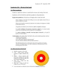
Figure 4. Integration <strong>of</strong> natural gas with the Hydrocol HTFT refinery.<br />
~ Gasoline<br />
4.1 Tar integration<br />
The configuration <strong>of</strong> a tar refinery is dictated by the nature <strong>of</strong> the coal<br />
pyrolysis products. In general the coal pyrolysis products are aromatic and<br />
contain sulphur, nitrogen and oxygen as hetero-atoms [54]. Since it is especially<br />
rich in phenolic material, phenol, cresols and xylenols (also collectively known<br />
as tar acids) can be extracted economically. In a fuel refining context<br />
hydroprocessing <strong>of</strong> the tar must be done in such a way that the hetero-atoms are<br />
effectively removed, but that the aromaticity is retained. In the petrol boiling<br />
range aromatics are required for octane and in the diesel boiling range aromatics<br />
are required for density. The products from a tar refinery therefore compliment<br />
that from a FT refinery nicely in terms <strong>of</strong> redressing octane and density<br />
shortcomings. Integration can take place downstream during fuel blending [9],<br />
but also at refinery level. Hydroprocessing <strong>of</strong> the more refractory hetero-atom-<br />
rich tar fractions may result in aromatics saturation. This destroys much <strong>of</strong> the<br />
benefit, but since the naphthenes can improve reforming performance, such<br />
streams can be combined with the FT feed to a reformer.<br />
4.2 Natural gas integration<br />
The condensate from natural gas can be seen as a paraffinic feedstock to<br />
the refinery. When the Hydrocol process was developed, all the condensable<br />
natural gas was used as direct blending stock with the FT derived material (Fig.<br />
4) [6]. Current fuel specifications would make such integration less likely. The<br />
condensate in the diesel boiling range can still be blended directly, but the<br />
condensate in the petrol boiling range requires refining.<br />
The processing scheme used for natural gas integration at the Mossel Bay<br />
refinery was developed with significant influence from the Sasol plants in<br />
Secunda. It targets the production <strong>of</strong> motor gasoline (Fig. 3) [15]. Therefore, it<br />
499
500<br />
includes conventional petroleum refinery units like catalytic reforming (C7-C10<br />
paraffins), alkylation (C4 paraffins and olefins) and skeletal isomerisation (C4-C6<br />
paraffins).<br />
It is interesting to note the co-processing <strong>of</strong> the NGL naphtha fraction with<br />
its equivalent synthetic cut. These are hydrogenated together before being<br />
catalytically reformed to improve its octane. The hydrogen used in the<br />
hydrogenation stage is obtained from the syngas used in the Synthol units. In an<br />
analogous way the Ca paraffins needed for alkylation are derived from the NGL.<br />
This is an efficient integration, but depending on the FT refinery configuration,<br />
other integration possibilities can also be considered.<br />
The diesel obtained from the Mossel Bay plant is a blend <strong>of</strong> distillates<br />
from the HTFT Synthol Light Oil and NGL with product obtained by<br />
oligomerisation <strong>of</strong> the light hydrocarbons derived from the FT synthesis. This<br />
diesel has good fuel characteristics but there are some quality differences<br />
associated with its aromatics content (Table 2) [49]. The Mossel Bay plant also<br />
produces some oxygenates including ethanol.<br />
Table 2<br />
Composition <strong>of</strong> the PetroSA diesel fuel<br />
NG-derived Zero-Sulphur<br />
Diesel Fuel Diesel (COD)<br />
Density at 20~ kg/1 0,8088 0,8007<br />
Distillation 9 IBP, ~ 222 229<br />
9 T90, ~ 322 323<br />
9 FBO, ~ 360 361<br />
Total sulphur % mass
level, but can be in the blending operation.<br />
products can also be mutually beneficial.<br />
501<br />
Exchange <strong>of</strong> partially refined<br />
4.5 Other integration schemes<br />
The integration <strong>of</strong> products from chemical work-up (aqueous FT product),<br />
especially alcohols, can be considered as alternative to etherification products for<br />
octane enhancement. In future it may also become desirable to integrate bio-<br />
derived materials. A FT refinery would have an advantage over an oil refinery<br />
for the integration <strong>of</strong> bio-derived material, since bio-derived material is rich in<br />
oxygenates which are already dealt with in the FT product. In any event, it is<br />
possible to combine the integration schemes in various ways, including complete<br />
integration. Each combination <strong>of</strong>fers opportunities to create unique product<br />
characteristics that would not have been possible from crude oil refining only, or<br />
FT refining only.<br />
5. THE FUTURE OF HTFT REFINING<br />
The evolution <strong>of</strong> the four HTFT refineries in South Africa over the past half-<br />
century has been instructive. During this period technology also evolved. Some<br />
<strong>of</strong> the technologies that are considered preferred refining options for FT<br />
products, were not yet fully developed when these refineries were built. The<br />
change in fuel specifications has been the main driver for change in the refining<br />
environment. In addition to this there was a realisation that the extraction <strong>of</strong> high<br />
value chemical commodities is beneficial.<br />
One may ask what the best configuration for a HTFT refinery is? A similar<br />
question has been pondered for crude refining, considering the impact <strong>of</strong><br />
environmental legislation and the increasingly stringent global fuel specifications<br />
[55, 56]. The answer is <strong>of</strong> course not straightforward and depends on factors like<br />
refinery location, size, capital constraints, feedstock cost and product pricing<br />
[57]. Some general trends can be noted though:<br />
9 Minimise wastage: Fuels refining is very sensitive to feed and product<br />
pricing. It is therefore better to select technologies that do not degrade<br />
products. Hydrogen addition is consequently preferable to carbon rejection.<br />
9 Upgrade paraffins. Paraffins are considered environmentally benign and are<br />
the only molecules not legislated by fuel specifications. Investing in<br />
technologies that upgrade paraffins or yield good paraffinic products is<br />
therefore prudent. Heavy paraffin hydroisomerisation and hydrocracking and<br />
light paraffin skeletal isomerisation fall into this category. Investing in such<br />
technologies would also make integration <strong>of</strong> natural gas condensates and<br />
LTFT products easier.<br />
9 Install clean technologies. The cleanest technology is the technology with the<br />
smallest environmental footprint to achieve a specific outcome. The
502<br />
environmental footprint refers to energy use, quantity and nature <strong>of</strong> waste and<br />
by-product formation. Although technologies like HF alkylation and<br />
chlorided platinum catalyst skeletal isomerisation produce desirable paraffinic<br />
products, it may be better to consider solid acid alkylation and Pt/zeolite<br />
skeletal isomerisation even though it might be slightly more expensive. It is<br />
less likely that such technologies will be affected by future environmentally<br />
driven legislation. This can also be seen as a form <strong>of</strong> responsible engineering.<br />
Target high value products. When a choice can be made between producing a<br />
fuel or higher value chemical, it is generally better for the process economics<br />
to opt for chemical production [58]. However, this should not be done at the<br />
expense <strong>of</strong> refinery flexibility or in the absence <strong>of</strong> a proven market for the<br />
chemical. The aim <strong>of</strong> chemical production must always be to improve<br />
pr<strong>of</strong>itability <strong>of</strong> the refinery, which implies that the facility must remain viable<br />
even when a downturn <strong>of</strong> the economy depresses the chemicals business. The<br />
best chemical products to target are those that have a sustainable competitive<br />
advantage and those that can easily be reincorporated into the refinery if<br />
necessary (Table 3). In this case low cost refinery units are preferred to avoid<br />
large capital investment in idle capacity. An alternative may be to use an<br />
imported hydrocarbon feed (e.g. a natural gas condensate fraction) to use the<br />
spare refining capacity created by the extraction <strong>of</strong> chemical components.<br />
Table 3<br />
Chemicals extraction, their impact and their reincorporation pathways in a refinery<br />
Chemical Extraction impact Refinery incorporation pathways<br />
Ethylene Marginal<br />
Propylene Refining less costly<br />
1-Hexene Octane gain<br />
1-Octene Octane gain<br />
Octenes mix Octane gain<br />
1-Decene Octane gain<br />
C12-~5 a-olefins Cetane loss<br />
Alkylate benzene to ethyl benzene for petrol.<br />
Recycle to the methane reformer.<br />
Metathesis with 1-butene to produce propylene.<br />
Aromatisation to produce aromatics and LPG.<br />
Alkylate benzene to cumene (fuel or chemical).<br />
Oligomerisation to fuel.<br />
Aromatisation to produce benzene.<br />
Hydrotreating / skeletal isomerisation for fuel.<br />
Aromatisation to produce aromatics for fuel.<br />
Reforming to produce aromatics-rich fuel.<br />
Aromatisation to produce aromatics for fuel.<br />
Reforming to produce aromatics-rich fuel.<br />
Reforming to produce aromatics-rich fuel.<br />
Hydrotreating to produce high Cetane diesel.<br />
Using these pointers with the preferred refining options discussed in the<br />
preceding section, it should be possible to have some indication <strong>of</strong> how an<br />
"optimal" future HTFT refinery should look like.
The art <strong>of</strong> HTFT refining lays not so much in meeting the fuel<br />
specifications as in exploiting the unique feed advantages <strong>of</strong>fered by the FT<br />
product. In conclusion it can be said that a HTFT product lends itself to an<br />
integrated fuels and chemicals refining approach. Refining with the aim to<br />
produce only fuels or only chemicals can be done, but this would be sub-optimal.<br />
6. UPGRADING OF LOW TEMPERATURE FISCHER-TROPSCH<br />
PRODUCTS<br />
6.1 Characterisation <strong>of</strong> the primary LTFT products<br />
The typical LTFT plant would produce two primary products: a light<br />
fraction, usually liquid at room temperature, and a heavy fraction, usually solid<br />
at the same conditions. The former is <strong>of</strong>ten named hydrocarbon condensate or<br />
simply condensate and includes hydrocarbon species with a final boiling point<br />
around 370~ The latter, also known as wax, includes the heavy paraffins.<br />
There are two other product streams: (i) light hydrocarbons gases, mostly<br />
generated during the FT synthesis, and (ii) reaction water, which include some<br />
dissolved oxygenates like alcohols and organic acids. The gas stream can have<br />
many applications as a fuel gas. The reaction water needs to be further processed<br />
and, at some locations, might even become a valuable product. There are several<br />
options for the purification <strong>of</strong> LTFT reaction water [59].<br />
The primary LTFT products have been described in detail in Chapter 3 and<br />
in the literature [60]. Typical distillation ranges for the LTFT Condensate and<br />
Wax are presented in Table 4.<br />
While the main species in the LTFT primary products are linear paraffins,<br />
smaller contents <strong>of</strong> olefins and oxygenates are present as well as some branched<br />
paraffins. The product slate for a particular system depends on the reactor<br />
configuration used, operating conditions and the catalyst that is employed [61].<br />
FT Wax production is about double <strong>of</strong> that <strong>of</strong> the FT Condensate.<br />
Table 4<br />
Typical distillation range for LTFT syncrude fractions<br />
FT Condensate<br />
Distillation Range % vol<br />
C5-160~ 44 3<br />
160-270~ 43 4<br />
270-370~ 13 25<br />
370-500~ - 40<br />
>500~ - 28<br />
FT Wax<br />
% vol<br />
The composition and yield immediately suggest that an effective approach<br />
to the refining <strong>of</strong> the LTFT primary products should include some form <strong>of</strong><br />
hydroprocessing. The recovery <strong>of</strong> the oxygenated hydrocarbons is always an<br />
503
504<br />
option depending on the scale <strong>of</strong> the operation. Further oxidation <strong>of</strong> the<br />
hydrocarbons can even be considered for niche applications [62].<br />
Hydroprocessing is a term used genetically for a number <strong>of</strong> processes that<br />
include hydrogen in heterogeneous reaction systems. This includes the<br />
technologies summarized in Table 5.<br />
Table 5<br />
Hydroprocessing based technologies<br />
Technology<br />
Purpose<br />
Remarks<br />
Hydrogenation<br />
Saturation <strong>of</strong> C=C bonds<br />
Hydrodesulphurisation Sulphur removal from CS bonds<br />
Hydrodeoxygenation Oxygen removal from CO bonds<br />
Hydrodenitrogenation Nitrogen removal from CN bonds<br />
Hydrodemetallation Metal removal from hydrocarbons<br />
Hydroisomerisation<br />
Hydrocracking<br />
Modification <strong>of</strong> molecular structures<br />
Cracking <strong>of</strong> large molecules and<br />
saturation <strong>of</strong> the C=C bonds<br />
<strong>Products</strong> are mostly<br />
isoparaffins<br />
Catalytic dewaxing<br />
Selective cracking <strong>of</strong> large molecules Some products are<br />
and saturation <strong>of</strong> C=C bonds usable as base oils<br />
Hydroprocessing <strong>of</strong>ten includes more than a single type <strong>of</strong> chemical<br />
reaction. In these cases the name <strong>of</strong> the most significant one is generally used to<br />
name the overall process [63]. One typical example is hydrocracking which is<br />
required to convert wax to middle distillates and also includes hydrogenation and<br />
hydroisomerisation. The FT primary products are sulphur free so<br />
hydrodesulphurization is obviously not applicable.<br />
6.2 LTFT primary product refining<br />
The LTFT primary products are ideally suited for upgrading to middle<br />
distillates with naphtha as the main co-product. The most suitable middle<br />
distillate product is diesel and the lighter and heavier fractions are usually<br />
undesirable due to limited markets and/or lower prices. The exception is the<br />
option to process wax for the production <strong>of</strong> lubricant base oils as discussed in<br />
Section 6.2.3. The production <strong>of</strong> kerosene/jet fuel as a co-product is optional.<br />
The kerosene cut is generally more valuable as a feedstock for the production <strong>of</strong><br />
detergent alkylates and is then separated prior to processing the remaining<br />
hydrocarbons. Even if this cut is not separated upfront it is still possible to cut<br />
the diesel to meet a typical flash point specification and allow all the lighter<br />
material to report to a high quality naphtha product.<br />
For middle distillate production, two types <strong>of</strong> processes could be used"<br />
hydrocracking <strong>of</strong> the heavy FT paraffinic wax and catalytic oligomerisation <strong>of</strong><br />
light olefins, i.e. C3-C5 olefins. The latter is especially applicable to the products<br />
from the Sasol Synthol HTFT process, where the bulk <strong>of</strong> the product consists <strong>of</strong><br />
these olefins. Only LTFT processes using fixed bed reactors would not consider
oligomerisation due to the low olefin content <strong>of</strong> the primary product. If the<br />
olefins lighter than diesel are converted to the diesel boiling range then the<br />
remaining naphtha may not require hydrogenation to improve the storage<br />
stability. Oligomerisation has already been discussed in relation to the refining <strong>of</strong><br />
HTFT products so the remainder <strong>of</strong> the discussion on the processing <strong>of</strong> LTFT<br />
products will focus on the hydroprocessing operations.<br />
The hydrocracking <strong>of</strong> the heavy paraffins serves two purposes, to reduce<br />
the boiling range to middle distillates and to improve the cold properties as the<br />
hydrocracked products are mostly branched.<br />
Currently the production <strong>of</strong> a high quality diesel fuel is a preferred option<br />
to the production <strong>of</strong> gasoline. This is because the very factors which count<br />
against FT gasoline, viz. product linearity and low aromatic content, are very<br />
positive factors in favour <strong>of</strong> high quality, i.e. high cetane number, diesel fuel.<br />
For maximum production <strong>of</strong> high quality diesel fuel the slurry bed reactor<br />
operating in the high wax selectivity mode with either iron or cobalt based<br />
catalysts, between 210 and 260 ~ and about 3Mpa, is the recommended route.<br />
The straight run FT diesel makes up about 20% <strong>of</strong> the total FT product and<br />
because it is predominantly linear it has a cetane number <strong>of</strong> about 75. Note that<br />
at present the specified cetane number <strong>of</strong> diesel fuels varies from about 40 to 50,<br />
depending on the location. The FT slurry reactors are operated for maximum<br />
wax production because subsequent down stream hydrocracking <strong>of</strong> the wax<br />
under relatively mild conditions makes the largest contribution to the final diesel<br />
fuel pool. In the case <strong>of</strong> cobalt catalysts there are two reasons for operating the<br />
FT process at high pressures, the wax selectivity increases with pressure (see<br />
Chapter 3, Section 9.3.2) and the degree <strong>of</strong> branching decreases [64]. The<br />
hydrocracking <strong>of</strong> wax with standard bi-functional catalysts was investigated at<br />
Sasol during the 1970's [65, 66]. Mild catalytic hydrocracking <strong>of</strong> the wax yielded<br />
about 80% diesel, 15% naphtha and 5% C1 to C4 gases. The product cut heavier<br />
than diesel was recycled to extinction. Simple calculation shows that the above<br />
product yields are the result <strong>of</strong> random beta scission along the linear wax chains.<br />
There is therefore a big incentive to improve the selectivity <strong>of</strong> the wax<br />
hydrocracking operation in order to increase the diesel cut yield. Some chain<br />
branching does occur during the wax hydrocracking operation and so the cetane<br />
number <strong>of</strong> the diesel fuel produced is somewhat lower than that <strong>of</strong> the straight-<br />
run FT diesel. The final diesel pool nevertheless has a cetane number <strong>of</strong> above<br />
70. The naphtha produced in the wax hydrocracking process consists only <strong>of</strong><br />
alkanes. The naphtha produced in the FT process also consists predominantly <strong>of</strong><br />
linear alkanes. To convert these two naphtha cuts to in- specification gasoline<br />
would require a considerable amount <strong>of</strong> further octane number upgrading.<br />
However, since these naphthas consist essentially <strong>of</strong> linear alkanes they would<br />
be an excellent feedstock for the production <strong>of</strong> ethylene by steam cracking,<br />
505
506<br />
yielding a much higher selectivity <strong>of</strong> ethylene than would be obtained from<br />
normal crude oil naphtha.<br />
6.2.1 Hydrocracking <strong>of</strong> heavy paraffins<br />
In contrast with petroleum hydrocracking feedstocks, the LTFT Wax is<br />
predominantly paraffinic, sulphur flee, metals free and practically aromatics flee.<br />
These characteristics are the ideal for hydrocracking and, as a consequence,<br />
LTFT feeds can be processed under much milder conditions than typical crude<br />
oil derived feeds, e.g. vacuum gas oils. In the hydrocracking <strong>of</strong> crude oil derived<br />
feeds pressures <strong>of</strong> typically as high as 150 bar are required to prevent coking <strong>of</strong><br />
the catalyst by the aromatic compounds. This is not necessary with paraffinic<br />
feeds and pressures between 35 and 70 bar are used to hydrocrack LTFT<br />
products using commercial hydrocracking catalysts. The relatively low levels <strong>of</strong><br />
oxygenates present in FT waxes, mainly alcohols and lesser amounts <strong>of</strong> acids<br />
and carbonyls, are easily and completely hydrodeoxygenated.<br />
The processing pressure is dependent on the hydrogenation capacity <strong>of</strong> the<br />
catalyst. When the hydrogen partial pressure is too low dehydrocyclisation <strong>of</strong> the<br />
paraffins starts to occur with the formation <strong>of</strong> polynuclear aromatics which<br />
eventually would lead to deactivation <strong>of</strong> the catalyst due to coking. Lower<br />
hydrogen/wax ratios lead to a decrease <strong>of</strong> conversion rate <strong>of</strong> the C22+ fraction<br />
and, after adjustment <strong>of</strong> reaction conditions to achieve the same conversion<br />
levels, an increase <strong>of</strong> both the iso-paraffin content and the selectivity to products<br />
lighter than diesel. Iso-paraffin content also increases with operating pressure.<br />
The hydrocracking process has to meet the following conditions:<br />
9 the chain length <strong>of</strong> the hydrocracked fragments should be predominantly in<br />
the desired products range,<br />
9 the components above said desired range should be hydrocracked in<br />
preference to those which are already in or below the desired range, and<br />
9 the production <strong>of</strong> less commercially attractive species, e.g. light hydrocarbon<br />
gases, should be minimized.<br />
Due to the clean nature <strong>of</strong> the feed, non-sulphided hydrocracking catalysts<br />
containing a noble metal component, like platinum, can be considered. The use<br />
<strong>of</strong> noble metals catalysts leads to higher hydroisomerisation activity and,<br />
consequently, better low temperature characteristics for the diesel product.<br />
Hydrocracking <strong>of</strong> FT Wax using a conventional catalyst has been studied<br />
over at least the last 30 years. <strong>Processing</strong> <strong>of</strong> Arge LTFT was reported in detail in<br />
a project sponsored by the US Department <strong>of</strong> Energy and completed by UOP and<br />
the Allied-Signal Engineering Materials Research Center in 1988 [67]. Sasol had<br />
earlier approached UOP to investigate the hydrocracking <strong>of</strong> FT waxes based on<br />
the promising results that Sasol had obtained from their in-house research (see<br />
Section 6.2). This included studying the effect <strong>of</strong> the reactor pressure on the<br />
hydrocracking performance from 35 to 70 bar. The feed contained some 14% <strong>of</strong><br />
species boiling in the distillates range. It was found that as the pressure
increased, the overall distillate yield first increased, passed through a maximum<br />
and subsequently decreased. The higher pressure inhibits secondary cracking and<br />
lighter product formation. The pour points <strong>of</strong> diesels produced from this program<br />
varied between -12~ and -37~ UOP reported that the FT Diesel derived was<br />
<strong>of</strong> extremely high quality, with a very high Cetane number, which can be<br />
blended with low-value refinery products such as light cycle oil to increase the<br />
volume <strong>of</strong> the diesel pool. The hydrocracking catalyst used in this program was a<br />
commercial sulphided catalyst designed for petroleum refining.<br />
Keeping some differences in mind, comparable trends were reported<br />
processing a comparatively light feed- it contained ca 61% wt <strong>of</strong> material<br />
already in the distillates range [68]. The catalyst used was platinum (0.3 mass%)<br />
on amorphous mesoporous silica-alumina. This program included testing over<br />
the same pressure range (35 to 70 bar) at temperatures between 330-355~ The<br />
degree <strong>of</strong> isomerisation in the hydrocracked products increased with an increase<br />
in the conversion. As a consequence, the freezing point <strong>of</strong> the kerosene was a<br />
very low -50~ and the pour point <strong>of</strong> the diesel -30~ remarkable figures<br />
considering the high fraction <strong>of</strong> linear light species in the feed.<br />
This approach <strong>of</strong> using a noble metal on amorphous silica alumina is<br />
likely to be the preferred approach for maximum production <strong>of</strong> highly desirable<br />
diesel blending material. It is likely that all the C14+ material will be treated<br />
using such catalysts due to the enhancement in cold flow properties resulting<br />
from the simultaneous isomerisation. A high blending Cetane value is retained<br />
and very little <strong>of</strong> the diesel range material in the feed is degraded into naphtha<br />
and kerosene.<br />
There are many technology licensors for hydroconversion processes<br />
including ChevronTexaco, UOP, IFP (Axens) and Haldor-Topsoe. Additionally<br />
catalysts can be obtained from these companies as well as from Akzo Nobel,<br />
Stid-Chemie and Axens among others.<br />
6.2.2 Hydrotreating <strong>of</strong> FT paraffins<br />
The quality <strong>of</strong> the primary FT products, both condensate and wax, can be<br />
improved by hydrotreating as Sasol has been doing commercially for many<br />
years. The primary objective <strong>of</strong> this process is to saturate olefins and oxygenates<br />
to the corresponding paraffins. This hydrogenation results in a hydrocarbon<br />
product that is stable when stored for long periods. Stability during storage is the<br />
primary objective for the hydrogenation <strong>of</strong> the hydrocarbon condensate or<br />
fractions there<strong>of</strong>. In the case <strong>of</strong> LTFT wax, the resulting product has better<br />
colour and stability. It is also possible, depending on the reaction conditions, to<br />
transform some <strong>of</strong> the linear hydrocarbons into branched species. In this case the<br />
crystallization temperature <strong>of</strong> the wax can also be influenced. These results are<br />
similar to those attainable when hydrotreating petroleum wax in a similar way<br />
[69]. However, as it was mentioned for hydrocracking, the required process<br />
507
508<br />
conditions are significantly less severe because <strong>of</strong> the chemical nature <strong>of</strong> the<br />
synthetic product.<br />
6.2.3 Catalytic dewaxing / hydroisomerisation<br />
Special hydroconversion operations may be used with fractions <strong>of</strong> the FT<br />
wax to produce lubricant base oils. The hydroisomerisation <strong>of</strong> petroleum-derived<br />
wax to base oil has been practiced for some time, and products from this process<br />
have been in the market for at least twenty years.<br />
9 In 1972 Shell commissioned their base oil manufacturing plant at the Petit-<br />
Couronne refinery in France. This plant uses severe hydrotreatment and<br />
solvent dewaxing to produce lubricating base oils. Feedstocks for this<br />
plant are waxy petroleum distillates, deasphalted oils and slack waxes,<br />
selected based on the desired base oil quality [70].<br />
9 Chevron, now ChevronTexaco, was the first to commercialize an all-<br />
hydroprocessing lube oil manufacturing process in 1984 at their Richmond<br />
refinery in California, USA. This design combined hydrocracking (for<br />
Viscosity Index upgrade) with catalytic dewaxing, which removed normal<br />
paraffins by cracking. Feedstocks to this process were petroleum vacuum<br />
gas oils [71]. Their ISODEWAXING process was brought into on-stream<br />
at the same refinery in 1993 [72]. This technology reaches the target pour<br />
point <strong>of</strong> the products in one step by isomerising part <strong>of</strong> the wax to base<br />
stocks and cracking part <strong>of</strong> it to fuels. In 2003 ChevronTexaco announced<br />
the commercial operation in Russia <strong>of</strong> an ISODEWAXING unit operating<br />
on petroleum wax [73 ].<br />
9 Mobil-developed technology, Mobil Selective Dewaxing (MSDW), started<br />
up commercially in their Jurong (Singapore) plant in 1997 [74]. More<br />
recently, ExxonMobil has announced the commercialization <strong>of</strong> a new wax<br />
isomerisation process at their Fawley refinery, UK [75]. The products<br />
from Fawley will have viscosity indexes <strong>of</strong> 140 and pour points <strong>of</strong>-18~<br />
This operation was scheduled to start by the end <strong>of</strong> 2003 using slack wax<br />
as feed.<br />
All <strong>of</strong> these processes can be used for processing FT wax, and the derived<br />
base oils have extremely high VI's and low volatilities, making them ideal bases<br />
for future high-performance lubricants.<br />
Fractionation into the various base oil products may be done upstream or<br />
downstream <strong>of</strong> the catalytic dewaxing step. This can be accomplished by using<br />
either high vacuum or short path distillation. The catalytic dewaxing operation<br />
may be followed by a hydr<strong>of</strong>inishing step to destroy any polynuclear aromatics<br />
formed in the first process step, stabilizing the base oil. The co-produced highly<br />
isomerised light fractions - diesel and naphtha, and optionally kerosene/jet fuel-<br />
have similar characteristics to the products from a hydrocracker but the yields are
lower. A process scheme similar to that used with petroleum derived waxes and<br />
suitable for the catalytic dewaxing <strong>of</strong> FT Wax is shown in Fig. 5.<br />
Wax ..] Catalytic ~ Hydr<strong>of</strong>inishing |<br />
"l Dewaxing Unit I I I<br />
l<br />
q<br />
Vac.<br />
Dist.<br />
Figure 5 Process scheme for the production <strong>of</strong> synthetic base oils from wax<br />
"l<br />
I<br />
Naphtha<br />
Diesel<br />
____~) Base Oils<br />
.~ Heavy Base<br />
Oil<br />
The catalytic dewaxing route to lubricant base oils is becoming the<br />
preferred processing option due to the lower capital and operating costs<br />
compared to conventional solvent dewaxing. Recently introduced catalytic<br />
dewaxing technology, e.g. ChevronLummus Global's ISODEWAXING and<br />
ExxonMobil's MWI (Mobil Wax Isomerisation), makes converting FT wax to<br />
base oils more economical than ever before.<br />
6.3 Hydroprocesssing catalysts for LTFT primary products<br />
6.3.1 Basic concepts<br />
Although the type <strong>of</strong> hydrocracker feed from a FT process differs from the<br />
normal refinery hydrocracker feed, e.g. VGO, the basic hydrocracking<br />
mechanism is the same and standard hydrocracking catalysts can be used. As in a<br />
refinery hydrocracking process, the choice <strong>of</strong> catalyst will depend on the<br />
required product slate. When high middle distillate selectivity is desired<br />
amorphous carriers would be chosen while, on the other hand, when maximum<br />
kerosene and naphtha selectivity are wanted, a mixed zeolite/amorphous carrier<br />
will probably be used.<br />
Commercial hydrocracking catalysts are dual function catalysts,<br />
containing a hydrogenation/dehydrogenation function, provided by the active<br />
metal(s) and an acidic function derived from the carrier, typically amorphous<br />
silica-alumina or crystalline silica-alumina, i.e. zeolites.<br />
According to generally accepted hydrocracking theory, the active metal<br />
sites promote dehydrogenation <strong>of</strong> the paraffins to olefins [76]. These are then<br />
509
510<br />
protonated on the acidic cartier to a carbenium ion. Finally, the carbenium ion<br />
undergoes isomerisation and cracking on the acid site.<br />
The ratio between the cracking function and hydrogenation function is <strong>of</strong><br />
utmost importance and can be adjusted to achieve the optimum activity and<br />
selectivity. Generally speaking, other things being equal, it can be stated that the<br />
higher the acidity at a given hydrogenation activity, the higher the activity and<br />
degree <strong>of</strong> isomerisation <strong>of</strong> the cracked products and the lighter the product slate.<br />
On the other hand, increasing the hydrogenation activity at a given acidity will<br />
lead to a heavier and less isomerised product. A higher acidity to hydrogenation<br />
ratio will produce a more isomerised diesel with improved cold temperature<br />
characteristics and with a slightly lower Cetane number.<br />
The amorphous carrier used in most commercial hydrocracking catalysts is<br />
silica-alumina, although other acidic carriers, like silica-magnesia, silica-titania<br />
and other mixed acidic oxides have been reported. Zeolite Y is the most<br />
frequently used zeolite, together with silica-alumina or alumina alone as a<br />
binder. The metals mostly used are either non-noble metal combinations like<br />
Co/Mo, Co/W, Ni/Mo or Ni/W as the sulphides or noble metals like Pt or Pd,<br />
either alone or in combination.<br />
The hydrocracking <strong>of</strong> LTFT products can be compared to the second stage<br />
hydrocracker operation used in petroleum refineries because no feed pre-<br />
treatment is required. Moreover, noble metal catalysts can also be used due to the<br />
fact that the feed is sulphur free. LTFT feeds do contain oxygenates, mainly<br />
alcohols, carboxylic acids, aldehydes and esters. These oxygenates are easily<br />
decomposed and hydrogenated under hydrocracking conditions to give the<br />
corresponding paraffins and water. Carboxylic acids may also undergo<br />
decarboxylation to CO2 plus a lower paraffin.<br />
6.3.2 Catalyst carriers<br />
The carrier functions both as a support for the metal and to provide the<br />
required acid functionality. As a carrier it has to have a high surface area for high<br />
dispersion <strong>of</strong> the metal as well as the fight pore size to allow easy diffusion <strong>of</strong><br />
the feed molecules into the catalyst and <strong>of</strong> the hydrocracked and isomerised<br />
products out <strong>of</strong> the catalyst. As the LTFT derived feed consists mainly <strong>of</strong> linear<br />
paraffins and does not contain polyaromatics, the requirement for sufficiently<br />
large pores is less stringent than in the case <strong>of</strong> petroleum feeds.<br />
The acidity, in the case <strong>of</strong> amorphous silica-alumina, depends on the<br />
preparation method as well as mainly on the silica/alumina ratio. BrOnsted<br />
acidity, which is accepted to be responsible for the formation <strong>of</strong> the carbenium<br />
ion intermediate, reaches a maximum at around 70% silica and is caused by<br />
tetrahedrally coordinated aluminium, which carries a negative charge,<br />
compensated by a proton which protonates the olefin, forming the reactive<br />
carbenium ion.
In the case <strong>of</strong> zeolites, the acidity depends also on the silica/alumina ratio<br />
as well as on the zeolite structure and the degree <strong>of</strong> exchange <strong>of</strong> sodium ions<br />
with protons. In mixed zeolite amorphous silica/alumina carriers the amorphous<br />
phase can either act simply as a binder at low level or at higher levels can also<br />
contribute to the activity.<br />
6.3.3 Metal components<br />
Most commonly the metals used in hydrocracking catalysts are a<br />
combination <strong>of</strong> group VIA (molybdenum, ttmgsten) and group VIIIA (cobalt,<br />
nickel). These metals are sulphided prior to use and kept in a sulphided state<br />
during the hydrocracking operation by sulphur compounds in the feed in the case<br />
<strong>of</strong> refinery feeds or by adding sulphur containing compounds in the case <strong>of</strong><br />
sulphur free feeds, like FT derived feeds.<br />
From hydrogenation studies it was found that the optimum ratio <strong>of</strong> the<br />
metals is:<br />
Mvin/(Mvm + Mvi) = --0,25, where MvIII is Co or Ni and MvI is Mo or W.<br />
The hydrogenation activity <strong>of</strong> the various couples decrease in the order:<br />
Ni-W > Ni-Mo > Co-Mo > Co-W.<br />
The hydrogenation activity is also function <strong>of</strong> the metal loading and<br />
dispersion. The required metal loading will depend on the desired balance<br />
between the cracking/isomerisation and hydrogenation functions.<br />
The noble metal content <strong>of</strong> hydrocracking catalysts is generally around<br />
0.5% or less. For non-noble metal the loadings are 3-8% nickel or cobalt oxides<br />
and 10-30% for molybdenum or tungsten oxides.<br />
6.4 Hydroprocessing flow sheet options to produce diesel<br />
The FT syncrude upgrading may be designed in a number <strong>of</strong><br />
configurations. These can be selected by process synthesis optimisation<br />
depending on the desired product slate [77]. Four <strong>of</strong> the possible process<br />
configurations are described in Table 6 and shown in Fig. 6.<br />
511
~<br />
.I Condensat, i ,~ ~l Cond,nsate<br />
[ 7 Fracti~176 ]. "l Hydrotreater<br />
i ; 2<br />
I i<br />
!<br />
, ',<br />
I t<br />
t I<br />
I !<br />
! I<br />
:<br />
9<br />
',<br />
,~<br />
I<br />
.~[ Wax<br />
Hydrocracker<br />
!<br />
!<br />
!<br />
Recycle<br />
!<br />
..1 Hydrotreated<br />
; "l <strong>Products</strong><br />
, Fractionator<br />
!<br />
I<br />
I<br />
!<br />
' !<br />
I<br />
I<br />
9 ~l Hydrocracked<br />
9 - <strong>Products</strong><br />
Fractionator<br />
Figure 6 Possible process configurations for the upgrading <strong>of</strong> LTFT products<br />
v<br />
F,-<br />
r- Naphtha<br />
~-- Diesel
Table 6<br />
Process configuration options for FT syncrude product upgrading<br />
Process Unit Possible Process Configuration<br />
2" Condensate Fractionator X X<br />
3* Condensate Hydrotreater (HT) X X<br />
4* HT Condensate Fractionator X<br />
5* Wax Hydroprocessing (HP) X X X<br />
6" HP <strong>Products</strong> Fractionator X X X<br />
Reference for the Fig. 6 numerals<br />
The FT condensate may be hydrogenated to saturate the double bonds <strong>of</strong><br />
olefins and eliminate oxygen by hydrodeoxygenation. After this process the<br />
product is a mixture <strong>of</strong> more chemically stable linear paraffins.<br />
As indicated before, hydroprocessing is used to upgrade FT wax to<br />
distillates or lube base oils and distillates. This process also converts the olefins<br />
and oxygenates to paraffins. The FT wax undergoes hydrocracking reactions and<br />
the product is a mixture <strong>of</strong> isomerised paraffins with low levels <strong>of</strong> naphthenic<br />
and aromatic species. High quality distillates can be obtained by proper selection<br />
<strong>of</strong> the catalyst and processing conditions.<br />
Hydrogenation is less costly than hydrocracking. For large scale plants a<br />
condensate hydrotreater should be used to process hydrocarbons that are already<br />
lighter than the desired middle distillate products (option 1) and also for the<br />
straight run middle distillates if cold flow properties are not an issue (option 2).<br />
Option 2 may also be chosen if it is desired to produce linear paraffin products.<br />
The condensate fractionator can also serve to remove light gases in order to<br />
stabilize the condensate for intermediate storage at atmospheric pressure. If a<br />
nearby naphtha cracker is available then the condensate fractionator will provide<br />
a naphtha product that need not be hydrogenated to ensure storage stability<br />
(option 3). Alternatively in this case, the straight run naphtha may be routed to<br />
an oligomerisation unit. As mentioned in section 6.2, the kerosene fraction<br />
should be separated using the condensate fractionator for use as a chemical<br />
feedstock. Finally option 4 may be selected due to its simplicity if the product<br />
flows can be handled by a single reactor.<br />
If both hydrotreating and hydrocracking are used then they may be operated<br />
at the same pressure and use a common hydrogen loop. Alternatively, the<br />
hydrotreater can be operated in a once through mode at a lower pressure and the<br />
hydrogen tail gas is then subsequently pressurized to be fed into the<br />
hydrocracker loop.<br />
The Sasol SPD TM process is configured in synthesis units whose capacity<br />
is set by the maximum practical capacity <strong>of</strong> some <strong>of</strong> its process units. The unit<br />
that defines the current 17 000 bpd-equivalent maximum capacity per train is the<br />
air separation unit. Recent advances in technology at Sasol give confidence for<br />
even larger Slurry Phase FT Reactor trains. The maximum capacity <strong>of</strong> the<br />
x<br />
x<br />
513
514<br />
product upgrading unit is comparable to those in oil refineries. Table 7 contains a<br />
mass balance for a 34 000 bpd-equivalent Sasol SPD TM product upgrading unit<br />
corresponding to Option 4 [77].<br />
Table 7<br />
Mass balance for a 34 000 bpd Sasol SPD TM product upgrading unit.<br />
Feed Sasol SPD TM <strong>Products</strong><br />
,, MSCFD bpd,<br />
Natural Gas 170 -<br />
9 LPO - 1000<br />
9 Naphtha - 7000- 9000<br />
9 Diesel - 24000- 26000<br />
Total <strong>Products</strong> - 34 000<br />
6.5 Alternative process options<br />
<strong>Processing</strong> <strong>of</strong> the LTFT primary products can be effected in many ways,<br />
following a process synthesis exercise. The final configuration will be selected<br />
considering:<br />
9 Site specific factors like plant capacity, available land and possible<br />
integration with other facilities.<br />
9 Market issues, including product(s) demand and logistics.<br />
9 Other factors like capital requirement and skilled labour availability.<br />
A few possible process configurations based on two primary LTFT liquid<br />
products are shown in Fig. 6. While these schemes make reference to only three<br />
final products, i.e. LPG, naphtha and diesel, it is completely possible to<br />
configure a plant in different ways. Other products might include solvents,<br />
kerosene, jet fuel, illuminating paraffin and base oils, as well as some olefinic<br />
petrochemicals.<br />
7. CHARACTERISTICS OF THE LTFT DISTILLATE PRODUCTS<br />
The main fuel product obtainable from the LTFT process is the proven low<br />
emissions diesel fuel (i.e. fuel for a compression ignition engine). In addition,<br />
this process also delivers a significant fraction <strong>of</strong> naphtha, an excellent feed for<br />
the production <strong>of</strong> olefins via steam cracking.<br />
7.1 LTFT diesel<br />
The first LTFT diesels were commercially produced in Germany around<br />
1935. This fuel was obtained by distillation <strong>of</strong> the light hydrocarbons from the<br />
FT reactors; there was no hydroprocessing and as a consequence it contained<br />
olefins and oxygenates. This scheme is presented in Fig. 7.
Coke Oven<br />
Gas<br />
Coke<br />
Steam<br />
Coke Gasifier HzS Removal<br />
Removal<br />
l <strong>Fischer</strong>-<strong>Tropsch</strong> I<br />
Synthesis I<br />
I<br />
Product<br />
Separation<br />
I<br />
Figure 7 Typical process scheme <strong>of</strong> the 1935-1945 German FT plants<br />
Light Gases<br />
~- Naphtha<br />
Kerosine<br />
Gas Oil<br />
Wax<br />
" Heavy Oil<br />
9 Tail Gas<br />
L Reaction<br />
Water<br />
The first LTFT plants <strong>of</strong> Sasol included a more complex processing<br />
scheme. The original concept, shown in Fig. 8, showed a high degree <strong>of</strong><br />
integration to maximize the benefits <strong>of</strong> the unique characteristics <strong>of</strong> the FT<br />
products [3]. This process scheme included eight separate units. While its<br />
objective was to produce fuels, gasoline and diesel, it also included the<br />
production <strong>of</strong> LPG and hydrogenated waxes. The quality <strong>of</strong> the gasoline was by<br />
improved by a Hot Refining step, a 400~ fixed catalyst bed treatment with two<br />
objectives: (a) conversion <strong>of</strong> oxygenates to other hydrocarbon species and (b)<br />
shifting the double bond in olefins to the centre <strong>of</strong> the molecule. Both changes<br />
improved fuel stability and octane number <strong>of</strong> the synthetic naphthas. The diesel<br />
was a blend <strong>of</strong> the straight run FT products and the cracked stock from the<br />
Paraformer, a thermal cracker unit- therefore still containing some olefins and<br />
oxygenates.<br />
Table 8 presents the quality <strong>of</strong> a sample obtained and analysed by the<br />
Allied forces after the war [78]. It is interesting to note that this straight run<br />
synthetic diesel produced using a cobalt FT catalyst, contained aromatic species<br />
and a significant amount <strong>of</strong> olefins.<br />
With time the processing <strong>of</strong> the LTFT primary products became more<br />
sophisticated. Most GTL technology licensors include different hydroprocessing<br />
arrangements that eventually will lead to comparable distillates. Therefore, in<br />
515
516<br />
broad terms, the information related to the characteristics and performance <strong>of</strong> the<br />
Sasol Slurry Phase Distillate TM (SPD TM) diesel that follows is also comparable to<br />
the other synthetic GTL LTFT-based distillates [79, 80].<br />
Table 8<br />
Quality <strong>of</strong> a World War II German FT diesel<br />
Density<br />
Distillation<br />
Flash Point<br />
Pour Point<br />
Bromine Number<br />
Reported value<br />
g/crn 3 (20~ 0.7681<br />
9 IBP, ~ 193<br />
9 T10, ~ 218<br />
9 T50, ~ 248<br />
9 T90, ~ 291<br />
9 FBP, ~ 311<br />
~ 78<br />
~ -1<br />
6.9<br />
The LTFT synthetic diesel has several important environmental advantages<br />
over conventional fuels. It has superior combustion characteristics due to their<br />
high Cetane number. Moreover, it is practically sulphur free and has a very low<br />
aromatics content. The basic properties <strong>of</strong> the Sasol SPD TM diesel are compared<br />
in Table 9 with those <strong>of</strong> two fuels: a CARB specification fuel and a commercial<br />
US 2-D diesel. The lower aromatics and sulphur contents <strong>of</strong> the Sasol SPD TM<br />
diesel are immediately evident.<br />
Table 9<br />
Basic properties <strong>of</strong> diesel fuels [75]<br />
US 2-D<br />
CARB<br />
Specification<br />
Sasol SPD TM<br />
Diesel<br />
ASTM D86 IBP, ~ 184 203 189<br />
Distillation T50, ~ 259 249 256<br />
T90, ~ 312 290 331<br />
Density kg/L 0,855 0,831 0,777<br />
Viscosity cSt (40~ 2,4 2,4 2,4<br />
Cetane Number 40 49 >70<br />
Aromatics wt % 32,8 6,7 0,5<br />
Sulphur mass % 0,028 0,022 0,001
Reactor<br />
Wax<br />
Hot<br />
Condensate<br />
Cold<br />
Condensate<br />
Tail<br />
Gas<br />
Reaction<br />
Water<br />
~[[ Vacuum<br />
Distillation ]<br />
I<br />
Cracked<br />
Product<br />
320~<br />
1 -~I CausticWash [<br />
~I TailGas i<br />
Recovery<br />
C8+<br />
320-370oc<br />
Hard Wax<br />
370-460~<br />
Atmospheric !<br />
Distillation<br />
l.~~l Hot Refining [<br />
Figure 8 The original process scheme for the LTFT Sasol 1 plant (ca 1957)<br />
Gatsch<br />
~i Paraforming I<br />
"1<br />
~i-ydr~176 i<br />
v!<br />
De-Oiling<br />
Bottoms Product<br />
Rerun and 1 ~<br />
Stabilisation I<br />
!<br />
I<br />
Hard Wax<br />
Slab Wax<br />
~- S<strong>of</strong>t Wax<br />
-" Diesel Oil<br />
9 ~ Gasoline<br />
~- C3-C4<br />
.~ Water +<br />
p..<br />
Oxygenates
518<br />
7.1.1 LTFT diesel as a blending component<br />
The Sasol SPD TM diesel was blended with the US 2-D specification fuel used for<br />
the emission tests to evaluate possible impact on quality. The typical quality for<br />
these blends is shown in Table 10 [79]. Blends <strong>of</strong> this fuel with the synthetic<br />
diesel resulted in improvements in Cetane number, and reductions in the sulphur<br />
content and the Cold Filter Plugging Point (CFPP), see Figs. 9 and 10. However,<br />
the synthetic fuel density is lower than that <strong>of</strong> petroleum fuels because <strong>of</strong> its very<br />
low levels <strong>of</strong> aromatics and naphthenics.<br />
70 - -15<br />
65 -20<br />
55 -30<br />
50 -35 i<br />
45 -40<br />
40 -45<br />
0% 10% 20% 30% 40% 50% 60% 70% 80% 90% 100%<br />
Sasol SPD Diesel in Blend, % vol.<br />
Figure 9 Sasol SPD TM Diesel US 2-D-Diesel Blends: Cetane Number and Cold Filter<br />
Plugging Point (CFPP)<br />
7.1.2 LTFT diesel fuel performance<br />
The emission tests were completed at the Southwest Research Institute<br />
(SwRI). The results show significant improvement when compared with the<br />
commercial US 2-D diesel and with the CARB specification fuel. The synthetic<br />
diesel produced lower emissions compared with the CARB fuel standard in all<br />
four groups: hydrocarbons, CO, NOx and particulates. The improvement relative<br />
to the commercial US 2-D diesel performance was even more significant [79].<br />
Blends <strong>of</strong> the Sasol SPD TM diesel with the US 2-D fuel showed reductions<br />
in emissions that were generally proportional to the amount <strong>of</strong> the synthetic fuel<br />
in the blend. Moreover, it was estimated that a blend <strong>of</strong> approximately 40% <strong>of</strong><br />
the Sasol SPD fuel with the US 2-D fuel used in the tests would result in<br />
equivalent emissions to the CARB fuel.
0.90 ........ i ....... i ...... ~ ...... i ....... i- ....... i ....... T ...... ~ ....... T ....... 250<br />
.............<br />
""i.<br />
" ....................................................................................<br />
i ! i ! i i i i<br />
0.87 . , . . .<br />
200<br />
0.81<br />
iiiiiiiiiiiill<br />
i i "''i'~. [Sulphurl i i<br />
iiiiiiiiiiii ..... ......... i .........<br />
0.78 .......... ! ......... i ......... i ......... I.'..D. ::ii.i~! .... i . ~ so<br />
! ! ! ! ",=<br />
. , I I I ",<br />
9 . ,<br />
0.75 ; :<br />
0% lO% 20% 30% 40% 50% 60% 70% 80% 90% 100%<br />
Sasol SPD Diesel in Blend, % vol<br />
Figure 10 Sasol SPD TM diesel US 2-D-diesel blends: density and sulphur content<br />
Table 10<br />
Average results from the emission tests with CARB, Sasol SPD TM and US 2-D diesel fuels<br />
Sasol SPD TM Diesel - US 2-D blend, % vol CARB<br />
0% 30% 50% 80% 100% Diesel<br />
Transient Emissions<br />
9 Hydrocarbons HC g/kWh 0.22 0.13 0.11 0.09 0.09 0.13<br />
9 Carbon<br />
Monoxide<br />
CO g/kWh 3.83 3.17 2.9 2.62 2.57 3.34<br />
9 NOx NOx g/kWh 7.05 6.17 5.72 5.3 5.08 5.96<br />
9 Particulate PM g/kWh 0.277 0.278 0.265 0.241 0.218 0.276<br />
9 BSFC (a) g/kWh 236 237 231 228 231 233<br />
Test Engine<br />
12,7 L DDC series 60 (1988), rebuilt to 1991 emission<br />
levels<br />
Rated Power 261 kW @ 1 800 rpm<br />
Peak Torque 1 830 Nm @ 1 200 rpm<br />
(a) Brake Specific Fuel Consumption (BSFC)<br />
If a blend is aimed at meeting the CARB specification then the boiling<br />
point range <strong>of</strong> the LTFT diesel will need to be adjusted accordingly. LTFT diesel<br />
can be blended with any current diesel fuel on the market to produce a blend that<br />
conforms to the CARB specification. In the case <strong>of</strong> a blend with US 2-D diesel,<br />
30% LTFT diesel in the blend is more than sufficient to meet the CARB<br />
specification in all respects except the aromatics content and the emissions<br />
performance is nearly equivalent. 80% LTFT diesel will be required to meet the<br />
CARB specification for aromatics but then a higher density third blend<br />
150<br />
100<br />
g~<br />
o<br />
k<br />
519
520<br />
component e.g. biodiesel and/or some other heavy oxygenated hydrocarbons will<br />
be required to meet the density specification. If biodiesel is used then it is also<br />
free <strong>of</strong> aromatics so that the combined amounts <strong>of</strong> LTFT diesel and biodiesel in<br />
the blend will be about 80%. This blend will have an emission performance that<br />
is far superior to conventional CARB diesel.<br />
7.1.3 LTFT diesel environmental characteristics<br />
Sasol also evaluated the biodegradability and ecotoxicity characteristics <strong>of</strong><br />
the Sasol SPD TM diesel, including some petroleum fuels for comparison.<br />
The biodegradability was measured using the modified Stunn OECD 301B<br />
method, based on the carbon dioxide evolution. It was found that the synthetic<br />
diesel can degrade rapidly and completely in an aquatic environment under<br />
aerobic conditions. Petroleum fuels tested simultaneously behaved differently,<br />
with lower degradation rates under the same conditions.<br />
The bacterial toxicity was determined using the OECD method 209 based<br />
on activated sludge respiration inhibition. From a toxicity perspective, the Sasol<br />
SPD TM diesel performed similarly to petroleum based fuels.<br />
7.1.4 LTFT diesel product applications<br />
The best use <strong>of</strong> the synthetic LTFT diesels will be to upgrade, by blending,<br />
the quality <strong>of</strong> conventional diesel fuels. Based on their superior quality, the<br />
synthetic distillates are the ideal, high value, blending component for upgrading<br />
<strong>of</strong> lower-quality stock derived from catalytic and thermal cracking operations,<br />
for example cycle oils [81, 82]. In 1948 JA Tilton from the Esso Standard Oil<br />
Company suggested that "there is a possibility that the <strong>Fischer</strong>-<strong>Tropsch</strong><br />
synthesis process may eventually be a source <strong>of</strong> premium quality Diesel fuels"<br />
[83]. It is interesting to note that it was also anticipated that blends <strong>of</strong> the use <strong>of</strong><br />
these high Cetane number diesels with lesser fuels were usable to meet a 50<br />
Cetane specification, concluding that these high Cetane number fuels "might be<br />
used either alone or as blending agents". The blend material from conventional<br />
processing includes product from FCC and Coker units. The blended final<br />
product will be low in sulphur and aromatics, a fuel compatible with demanding<br />
environmental legislation. Hence the products could enter a market where the<br />
LTFT diesel characteristics are valued as blend material to meet local<br />
requirements. It is also possible to use this fuel as a neat fuel in applications<br />
where its premium characteristics are desired.<br />
7.2 LTFT naphtha<br />
The characteristics and applications <strong>of</strong> the Sasol SPD TM naphthas have been<br />
the subject <strong>of</strong> presentations at recent international meetings [77, 84]. Four LTFT<br />
naphthas can be produced using the process configurations summarised in Table
11; all <strong>of</strong> these are products obtainable from a Sasol SPD TM plant. Their typical<br />
characteristics are presented in Table 12.<br />
Table 11<br />
Process schemes usable for the production <strong>of</strong> Sasol LTFT naphthas<br />
FT Naphtha Production Scheme<br />
SR Straight Run Fractionation <strong>of</strong> FT condensate<br />
HT SR Hydrogenated Straight Run Hydrotreating and fractionation <strong>of</strong> FT<br />
condensate<br />
HX Hydrocracked Hydrocracking and fractionation <strong>of</strong> FT wax<br />
SPD Sasol SPD Blend <strong>of</strong> liT SR and HX naphthas<br />
Table 12<br />
Typical characteristics <strong>of</strong> the Sasol SPD TM naphthas<br />
Naphtha<br />
SR HT SR HX SPD<br />
ASTM D86 Distillation<br />
9 IBP, ~ 58 60 49 54<br />
9 T10,~ 94 83 79 81<br />
9 T50, ~ 118 101 101 101<br />
9 T90, ~ 141 120 120 120<br />
9 FBP, ~ 159 133 131 131<br />
Density, kg~ (20~ 0.710 0.683 0.688 0.685<br />
Cloud Point, ~ - predicted -51 -54 -35 -33<br />
Flash Point, ~ -9 - 18 -21 -20<br />
Cetane Number n/a 42.7 30.0 39.6<br />
Total sulphur, mg/L<br />
Composition, % wt<br />
522<br />
A comparison <strong>of</strong> the characteristics <strong>of</strong> the Sasol SPD TM naphtha with<br />
typical petrochemical naphthas is shown in Table 13. The synthetic product can<br />
be described as a highly paraffinic low sulphur naphtha with non detectable<br />
levels <strong>of</strong> aromatic species.<br />
The Sasol SPD TM naphtha used in this research program was the fully<br />
hydrogenated product derived from the Isocracking| <strong>of</strong> the Sasol SPD FT<br />
syncrude. The program included testing the Sasol SPD TM naphtha performance at<br />
several cracking severities and a separate test designed to evaluate the coke<br />
build-up at high cracking severity. The results were compared with typical yields<br />
reported for two petroleum naphthas [85], and with that <strong>of</strong> a highly paraffinic<br />
product.<br />
The results experimentally determined for the Sasol SPD TM naphtha are<br />
compared with those expected when cracking petroleum naphthas at the same<br />
severity level under the relatively long residence time attainable during the<br />
research rtms. This comparison is presented in Table 14.<br />
Table 13<br />
Quality <strong>of</strong> the Sasol SPD naphtha and the petroleum reference naphthas<br />
Highly Typical<br />
Paraffinic Petroleum<br />
Naphtha Heavy Naphtha<br />
0.660 0.717<br />
The optimum olefins yields obtainable from any naphtha depend on the<br />
maximum cracking severity attainable at commercial conditions. This in turn<br />
depends on the chemical composition <strong>of</strong> the naphtha and, up to certain extent, to<br />
the physical configuration <strong>of</strong> the cracker unit. The former is evident in Figs. 11<br />
and 12 which show the ethylene and commercial olefin yields at different<br />
cracking severities for the synthetic and the two petroleum feedstocks.<br />
It is <strong>of</strong> relevance to indicate that while this kind <strong>of</strong> performance was<br />
directionally predictable, it was not fully quantified. Indeed, hydroprocessing has<br />
been previously reported as a crucial pre-treatment stage to improve the<br />
properties <strong>of</strong> FT naphthas for conversion to lower olefins. [86].<br />
Table 14<br />
Research performance comparison <strong>of</strong> the Sasol SPD TM naphtha<br />
Typical Petroleum Typical Petroleum<br />
Light Naphtha Heavy Naphtha<br />
P/Emassratio 0.77 0.68 0.59 0.82 0.74 0.65<br />
Sasol SPD TM Naphtha<br />
523<br />
0.71 0.59 0.50 0.40<br />
Yield (wt %)<br />
Ethylene 24.1 27.0 29.3 19.4 21.9 24.0 26.5 32.3 35.7 37.5<br />
Propylene 18.7 18.4 17.2 16.0 16.1 15.5 18.8 19.1 17.8 15.0<br />
1,3-Butadiene 4.0 4.2 4.4 3.8 4.1 4.3 2.9 3.8 4.2 4.2<br />
Light Olefins 46.7 49.6 50.8 39.2 42.1 43.8 48.2 55.2 57.7 56.7<br />
Other Olefins 8.2 6.9 5.4 8.3 7.3 6.1 9.9 8.4 6.2 4.1<br />
Hydrogen 0.6 0.7 0.8 0.5 0.6 0.7 0.6 0.7 0.8 0.9<br />
Methane 12.8 14.6 16.3 10.9 12.6 14.2 10.2 13.0 14.9 16.2<br />
Other Paraffins 11.8 9.4 7.5 11.8 9.4 7.3 5.1 5.3 4.8 4.4<br />
Alkynes 0.4 0.7 0.9 0.4 0.7 1.0 0.4 0.7 1.1 1.4<br />
C5+ Liquids 19.4 18.1 18.2 28.8 27.2 27.0 25.7 16.9 14.4 16.3<br />
Total <strong>Products</strong> 100 100 100 100 100 100 100 100 100 100<br />
The coking rate for LTFT Naphtha under commercial conditions is<br />
expected to be lower than that <strong>of</strong> conventional feeds, meaning that run lengths in<br />
commercial steam cracking operations using LTFT Naphtha can be expected to<br />
be longer than those expected using conventional naphthas at similar cracking<br />
severities.
524<br />
100 -[ ........................... -:, .............. -: .............. ~, .............. ~, .............. ,-- .............. ,o .............. ,: ............... T .............. ]<br />
95 ~ . . . . . . . . . . -: ......... -: .......... 1- ......... i. ......... : ......... l .........<br />
| i i i ~'~ SPDNa~htha i :: i !<br />
90 . . . . . . . . :<br />
~ ~'~ ~ I ......... i iiiii ......... iiii!iiiii 9 ......... iiiiiiiiiiiiii~i .i ......... -. ....... =. .......... i .. ......... i " ......... i 9 ......... " i ......... ~ i<br />
..~ 80 -r ......... ~ ' " " . ' " .... :~M"" ....... ~ ......... ~ ......... ~ .........<br />
' : .' 9 : : : '. ..<br />
ca 75 .- ........ . ......... . ......... . ......... . . . . . . . . . . . . . . . . :. ......... : ......... : ......... ~<br />
a~<br />
~ 7~ ......... i ......... i ......... i ......... i ......... i .......... i ........ ~ ........ ' ......... i<br />
9 -~ . . . . . : : . : :<br />
65 1 ......... : ......... l .............................................................................<br />
cq<br />
ca<br />
...i<br />
60 ......... ' ......... ; ......... ; ......... -1 ......... .I . . . . . . . . . . . . . l .........<br />
~ ......... ~ ............................................. ..~.~ ~.~,..~ ..... ....<br />
1 ' ~ ~ ~ ~ ' ' '<br />
~ i<br />
~ a~-----.. ~<br />
~0~_ i i i i i .: " i " i ,:"1 !<br />
85<br />
ca<br />
-- 80<br />
o<br />
ca<br />
o 75<br />
ca<br />
,=i<br />
~ 7O<br />
0.35 0.40 0.45 0.50 0.55 0.60 0.65 0.70 0.75 0.80 0.85<br />
P/E Ratio (mass)<br />
Figure 11 Comparison <strong>of</strong> the relative ethylene yields<br />
100 .............. . . .<br />
95 ""SPD'N'a'phtha ........ " ................ {<br />
90 ' '<br />
iiiiiiiiiiiiiiiiiii<br />
. . . . . . . . . . . . . . . . ,. . . . . . . . . . . . . . . . . ,. . . . . . . . . . . . . . . . d.. . . . . . . . . . . . . . . . .I . . . . . . . . . . . . . . . . ., . . . . . . . . . . . . . . . . -'<br />
: ! i Light Naphtha i<br />
i i iiiiiiiiiii i iiii iiiiiiiiiiii iiiiiiiiiiiiii iiiiiiiiiii, i<br />
65 : ! i ! i<br />
: : : :<br />
. o<br />
9 i<br />
60 ~ ~ ;<br />
0.30 0.40 0.50 0.60 0.70 0.80 0. 90<br />
P/E Ratio (mass)<br />
Figure 12 Comparison <strong>of</strong> the relative total olefin yields
7.2.2 LTFT naphtha fuel performance<br />
Excluding the SR fuel, all these LTFT naphthas can be regarded as<br />
paraffinic. This suggested evaluating them as possible distillates. The Cetane<br />
numbers for the HT SR and the SSPD fuels are marginally below typical values<br />
found in commercial diesel. As expected, being more isomerised, that <strong>of</strong> the HX<br />
naphtha was even lower. The SR naphtha contains significant levels <strong>of</strong> both<br />
olefins and alcohols that reduced its Cetane number and it was decided not to test<br />
this fuel in the Cetane machine.<br />
The emissions and specific fuel consumption tests were carried out at the<br />
Sasol Oil R&D facilities [77]. A commercial summer grade diesel fuel produced<br />
at a South African oil refinery was also tested for comparison purposes under<br />
identical conditions. The same standard diesel fuel engine settings were used for<br />
all fuels. The results from the engine test are shown in Table 15.<br />
It is evident from their composition that these LTFT naphthas that they are<br />
far from being compatible with that high octane naphthas usable in gasoline<br />
blends.<br />
Table 15<br />
Diesel engine and emissions performance <strong>of</strong> the Sasol SPD naphthas<br />
Sasol FT Naphtha<br />
SR HT SR HX SSPD<br />
Engine Mercedes Benz 407T<br />
Test condition 1 400 rpm<br />
Load 553 Nm<br />
BSFC (Brake Specific Fuel<br />
Consumption), g/kWh<br />
216.4 206.2 201.5<br />
CO emissions, g/kWh 0.87 0.79 1.03<br />
CO2 emissions, g/kWh 668.1 676.1 698.9<br />
Hydrocarbon emissions,<br />
g/kWh<br />
0.398 0.373 0.445<br />
NOx, emissions g/kWh 13.59 12.55 12.47<br />
Bosch Smoke Number 0.32 0.37 0.31<br />
South<br />
African<br />
Diesel<br />
206.8 216.8<br />
0.83 1.11<br />
670.1 700.9<br />
0.301 0.138<br />
12.55 16.99<br />
0.37 0.67<br />
7.2.3 LTFT naphtha as a blending component<br />
Petroleum refiners producing diesel fuels for cold weather specifications usually<br />
change the boiling points <strong>of</strong> their fuels to improve their cold flow characteristics,<br />
making them compatible with low temperature operation. This results in lower<br />
production volumes, not only <strong>of</strong> diesel fuels but also <strong>of</strong> other light products. The<br />
characteristics <strong>of</strong> the Sasol synthetic naphthas suggested its possible use in<br />
blends with diesel fuels suitable for low temperature operation.<br />
525
526<br />
60.0 . . : . . .<br />
i i ! i i i<br />
. . o . . .<br />
' .... : 9 : : : ;<br />
:" : : : : i<br />
,,.o ......... i:::-i ....... ~ '!': : : : :i: : ...... i ......... ! ......... ! ......... i .......... i ........<br />
! " : : "'$ i i " i<br />
o ~ :: ! :: ~,,.. !crve! ::<br />
~ 0.80<br />
40.0<br />
Cetane l~umbe~, i i :: i :: "'- i<br />
, , , . . , . ,<br />
: : : : : : : :<br />
i i i ~ ! i i :<br />
, , , , , . ,<br />
35.0 ; ; ; ; ; ; ; ;<br />
0% 10% 20% 30% 40% 50% 60% 70% 80% 90%<br />
Sasol SPD Naphtha-Diesel Blend, % vol.<br />
Figure 13 Sasol SPD TM Naphtha-Diesel blend- Cetane number & CFPP<br />
090 ....... i .......... i .......... i ........... ! ........... i ........ i .......... T .......... ,o 70<br />
o.85 ......... i ......... :. .... ::--~-: ........ " ......... .: ......... i ......... -: ......... 4 .......... ~ ........ 60<br />
100%<br />
-10<br />
o<br />
-2o .~-<br />
.,=,<br />
-3o _~<br />
,.=,<br />
.,=,<br />
-40 N<br />
40 ~<br />
g<br />
~, 0.75 20<br />
0.70 0<br />
0.65 -20<br />
0% 10% 20% 30% 40% 50% 60% 70% 80% 90% 100%<br />
Sasol SPD Naphtha-Diesel Blend, % vol.<br />
Figure 14 Sasol SPD TM Naphtha-Diesel blend- specific Gravity & Flash Point<br />
Blends <strong>of</strong> Sasol SPD TM naphtha with conventional diesels would meet<br />
winter grade fuel specifications [77, 87]. The quality <strong>of</strong> the final product will<br />
depend on the fraction <strong>of</strong> naphtha included in-the blend, as shown in Figs 13 and<br />
14. As an additional benefit, this practice would help maintaining the production<br />
volumes <strong>of</strong> jet fuel. Maximising jet fuel recovery, while maintaining diesel<br />
volumes, should translate into better economic results for most oil refineries. All<br />
-50<br />
50<br />
10<br />
-10
FT naphthas have the added benefit <strong>of</strong> having sulphur contents below 1 ppm.<br />
Their inclusion in blends should assist refiners in meeting low sulphur content<br />
specifications.<br />
7.3 Other applications for LTFT products<br />
The applications for products derived from LTFT Syncrude are the same as<br />
those <strong>of</strong> most crude oils. However, due to its ultralow sulphur content, all FT-<br />
based products will need less processing to meet strict environmental<br />
specifications.<br />
The low sulphur content and highly paraffinic nature <strong>of</strong> the FT derived<br />
products make them ideal candidates for fuel cell applications [88]. In this case,<br />
their low aromatic and naphthenic contents become an additional advantage that<br />
results in extremely low carbon deposition in the reforming catalysts.<br />
High-octane naphthas could be obtained from FT syncrude after adequate<br />
processing. Although this is technically attainable, there are better and more<br />
cost-effective petroleum processes for this purpose.<br />
The possible use <strong>of</strong> the LTFT wax as rocket propellant is another<br />
interesting option [89].<br />
8. LARGE SCALE PRODUCTION OF HIGH VALUE LTFT PRODUCTS<br />
Most <strong>of</strong> the recent interest for future LTFT GTL plants has been for the use <strong>of</strong><br />
supported cobalt catalyst in slurry phase reactors. There are good reasons for this<br />
approach not least <strong>of</strong> which is the relative simplicity <strong>of</strong> the process that lends<br />
itself to successful application at remote locations. Work is in progress to<br />
construct plants at Ras Laffan, Qatar and Escravos, Nigeria. This concept uses<br />
the Sasol Slurry Phase Distillate TM (Sasol SPD TM) process or the Shell Middle<br />
Distillate Synthesis (SMDS TM) process to produce mainly diesel fuel with by-<br />
product naphtha.<br />
Although these processes are ideally suited for the production <strong>of</strong> diesel,<br />
Sasol and Shell have recognized the opportunity to produce chemicals in a<br />
synergistic manner.<br />
There was a time when it was thought that future large scale GTL plants<br />
will not be able to target higher value hydrocarbon products due to limitations<br />
imposed by the size <strong>of</strong> the markets. For exan~le, Shell stated in 1995 that their<br />
future SMDS projects will be based on transportation fuels only [81, 82].<br />
However, for at least three important products namely ethylene, propylene and<br />
lubricant base oils (also known as waxy raffinate), the markets are large enough<br />
to sustain large scale co-production <strong>of</strong> these products. In the recently announced<br />
Shell plant in Qatar, that is eventually expected to produce about 140 000 bbl/d<br />
527
528<br />
<strong>of</strong> hydrocarbon products, the production <strong>of</strong> lubricant base oils and paraffins is<br />
included in the initial product slate.<br />
Sasol has proposed two approaches for the large scale production <strong>of</strong> higher<br />
value hydrocarbons via FT technology. Firstly, there is the option to modify the<br />
product upgrading schemes for the primary products from supported cobalt<br />
catalyst to produce olefins and lubricant base oils in addition to diesel fuel [90].<br />
Secondly, Sasol believes that its proprietary iron based FT processes can be used<br />
to further enhance or expand the production <strong>of</strong> higher value hydrocarbon<br />
products with fuels as significant by-products. Being highly olefinic, the nature<br />
<strong>of</strong> the products from iron catalysts is well suited to extraction and processing for<br />
the production <strong>of</strong> commodity chemicals. This is discussed in more detail in<br />
Chapter 5.<br />
REFERENCES<br />
[1] A. de Klerk, Hydrotreating in a <strong>Fischer</strong>-<strong>Tropsch</strong> refinery, 2 nd Sub-Saharan Africa<br />
Catalyst Symposium, Swakopmund, Namibia 5-7 Nov. (2001).<br />
[2] J. Stell, Worldwide catalyst report, Oil Gas J., 99:41 (2001) 56-76.<br />
[3] J.C. Hoogendoorn, J.M. Salomon, Sasol: World's largest oil-from-coal plant, British<br />
Chem. Eng., (1957) 238-244, 308-312, 368-373,418-419.<br />
[4] M.E. Dry, Sasol's <strong>Fischer</strong>-<strong>Tropsch</strong> experience, Hydrocarbon Process., Aug. (1982),<br />
121-124<br />
[5] M.E Dry, Chemicals produced in a commercial <strong>Fischer</strong>-<strong>Tropsch</strong> process, Industrial<br />
Chemicals via C1 Processes, ACS Symp. Ser., 328 (1987) 18-33.<br />
[6] P.C. Keith, Gasoline from natural gas, Oil Gas J., 15 Jun. (1946), 102-112.<br />
[7] M.L. Kastens, L.L. Hirst and R.G. Dressier, An American <strong>Fischer</strong>-<strong>Tropsch</strong> plant, Ind.<br />
Eng. Chem., 44:3 (1952) 450-466.<br />
[8] J.S. Swart, G.J. Czajkowski and R.E. Conser, Sasol upgrades synfuels with refining<br />
technology, Oil Gas J., 79:35 (1981) 63-66.<br />
[9] J.N. Marriott, Sasol process technology- The challenge <strong>of</strong> synfuels from coal,<br />
ChemSA, 12:8 (1986) 174-178.<br />
[10] M.D. Schlesinger, H.E. Benson, E.M. Murphy, H.H. Storch, Chemicals from the<br />
<strong>Fischer</strong>-<strong>Tropsch</strong> synthesis, Ind. Eng. Chem., 46:6 (1954) 1322-1326.<br />
[11] J. Meintjes, Sasol 1950-1975, Tafelberg, Cape Town, 1975.<br />
[12] J. Collings, Mind over matter. The Sasol story: A half-century <strong>of</strong> technological<br />
innovation, Sasol, Johannesburg, 2002.<br />
[13] C. Steyn, The role <strong>of</strong> Mossgas in Southern Africa, 2 nd Sub-Saharan Africa Catalyst<br />
Symposium, Swakopmund, Namibia, 5-7 Nov (2001).<br />
[14] O.R. Minnie, F.W. Petersen and F.R. Samadi, Effect <strong>of</strong> 1-hexene extraction on the COD<br />
process conversion <strong>of</strong> olefins to distillate, 2003 South African Chemical Engineering<br />
Congress, Sun City, South Africa 3-5 Sep. (2003).<br />
[ 15] J. Terblanche, The Mossgas challenge, Hydrocarbon Eng., Mar. (1997) 2-4.<br />
[16] KBR, The first Superflex Project- <strong>Fischer</strong>-<strong>Tropsch</strong> liquids to propylene, 5 th EMEA<br />
Petrochemicals Technology Conference, Paris, France (25-26 Jun 2003).<br />
[17] X. Song, A. Sayari, Sulfated zirconia as a cocatalyst in <strong>Fischer</strong>-<strong>Tropsch</strong> synthesis,<br />
Energy & Fuels, 10:3 (1996) 561-565.
[ 18] P.G. Smirniotis and W. Zhang, Effect <strong>of</strong> the Si/A1 ratio and <strong>of</strong> the zeolite structure on<br />
the performance <strong>of</strong> dealuminated zeolites for the reforming <strong>of</strong> hydrocarbon mixtures,<br />
Ind. Eng. Chem. Res., 35 (1996) 3055-3066.<br />
[19] A. de Klerk, Deactivation behaviour <strong>of</strong> Zn/ZSM-5 with a <strong>Fischer</strong>-<strong>Tropsch</strong> derived<br />
feedstock, in S.D Jackson, J.S.J. Hargreaves and D. Lennon (eds), Catalysis in<br />
application, Royal Society <strong>of</strong> Chemistry, Cambridge, 2003, 24-31.<br />
[20] ASTM DS 4B, Physical constants <strong>of</strong> hydrocarbons and non-hydrocarbon compounds,<br />
ASTM, Philidelphia, 1988 (2ed).<br />
[21] S.M. Ozmen, H. Abrevaya, P. Barger, M. Bentham and M. Kojima, Skeletal<br />
isomerisation <strong>of</strong> Ca and Cs olefins for increased ether production, Fuel Reformulation,<br />
3:5(1993) 54-59.<br />
[22] J-L. Duplan, P. Amigues, J. Verstraete and Ch. Travers, Kinetic studies <strong>of</strong> the skeletal<br />
isomerization <strong>of</strong> n-pentenes over the ISO-5 process catalyst, Proc. Ethylene Prod. Conf.,<br />
5 (1996) 429-449.<br />
[23] F.M. Floyd, M.F. Gilbert, M. P6rez and E. KOhler, Light naphtha isomerisation,<br />
Hydrocarbon Eng., Sep. (1998) 42-46.<br />
[24] P.J. Kuchar, R.D. Gillespie, C.D. Gosling, W.C. Martin, M.J. Cleveland and P.J. Bullen,<br />
Developments in isomerisation, Hydrocarbon Eng., Mar. (1999) 50-57.<br />
[25] P.W. Tamm, D.H. Mohr and C.R. Wilson, Octane enhancement by selective reforming<br />
<strong>of</strong> light paraffins, Stud. Surf. Sci. Catal., 38 (1988) 335-353.<br />
[26] T.R. Hughes, R.L. Jacobson and P.W. Tamm, Catalytic processes for octane<br />
enhancement by increasing the aromatics content <strong>of</strong> gasoline, Stud. Surf. Sci. Catal., 38<br />
(1988) 317-333.<br />
[27] R.L. Peer, R.W. Bennett, D.E. Felch and E. Von Schmidt, UOP Platforming leading<br />
octane technology into the 1990's, Catal. Today, 18 (1993) 473-486.<br />
[28] C. Hodge, Comment: More evidence mounts for banning, not expanding, use <strong>of</strong> ethanol<br />
in US gasoline, Oil Gas J., 101 6 Oct. (2003) 18-20.<br />
[29] P.C. Weinert and G. Egl<strong>of</strong>f, Catalytic polymerization and its commercial application,<br />
Petroleum Process., Jun. (1948) 585-593.<br />
[30] S.A. Tabak, F.J. Krambeck, and W.E. Garwood, Conversion <strong>of</strong> propylene and butylene<br />
over ZSM-5 catalyst, AIChE J., 32:9 (1986) 1526-1531.<br />
[31 ] F. Nierlich, Oligomerize for better gasoline, Hydrocarbon Process., Feb. (1992) 45-46.<br />
[32] J-F. Joly, Aliphatic alkylation, in P. Leprince (ed), Petroleum Refining 3: Conversion<br />
Processes, Editions Technip, Paris, 2001,257-289.<br />
[33] M. Golombok and J. De Bruijn, Dimerization <strong>of</strong> n-butenes for high octane gasoline<br />
components, Ind. Eng. Chem. Res., 39 (2000) 267-271.<br />
[34] S.T. Sie, Acid-catalyzed cracking <strong>of</strong> paraffinic hydrocarbons. 1. Discussion <strong>of</strong> existing<br />
mechanism and proposal <strong>of</strong> a new mechanism, Ind. Eng. Chem. Res., 31 (1992) 1881-<br />
1889.<br />
[35] J.F. Boucher, G. Follain, D. Fulop and J. Gaillard, Dimersol X process makes octenes<br />
for plasticizer, Oil Gas J., 80, 29 Mar (1982) 84-86.<br />
[36] R.H. Friedlander, D.J. Ward, F. Nierlich and J. Neumeister, Make plasticizer olefins via<br />
n-butene dimerisation, Hydrocarbon Process., Feb. (1986) 31-33.<br />
[37] M. Freemantle, Designer solvents, Chem. Eng. News, 30 Mar (1998) 32-37.<br />
[38] E.J. Swain, U.S. MTBE production at a record high in 1998, Oil Gas J., 97:24 (1999)<br />
99-101.<br />
[39] G. Parkinson, All sides pumped up for MTBE ban, CherrL Eng., (Jun 1999) 49.<br />
[40] H. Becker, Process for the manufacture in pure form <strong>of</strong> 1-pentene or an alpha-olefin<br />
lower than 1-pentene, US patent No. 6 483 000 Nov. (2002).<br />
529
530<br />
[41 ] F.D. Rossini, Chemical thermodynamics in the petroleum industry, J. Inst. Petroleum,<br />
58:564 (1972) 279.<br />
[42] A.O.I. Krause and L.G. Hammarstr0m, Etherification <strong>of</strong> isoamylenes with methanol,<br />
Appl. Catal., 30 (1987) 313-324.<br />
[43] R.S. Karinen, J.A. Linnekoski and A.O.I. Krause, Etherification <strong>of</strong> C5- and C8-alkenes<br />
with Cx- to C4-alcohols, Catal. Lett., 76 (2001) 81-87.<br />
[44] J.D. Swift, M.D. Moser, M.B. Russ and R.S. Haizmann, The RZ platforming process:<br />
something new in aromatics technology, HTI Quarterly, Autumn (1995) 86-89.<br />
[45] T. Fukunaga and V. Ponec, The nature <strong>of</strong> the high sensitivity <strong>of</strong> Pt/KL catalysts to<br />
sulphur poisoning, J. Catal., 157 (1995) 550-558.<br />
[46] T. Zhang and R. Datta, Ethers from ethanol. 3. Equilibrium conversion and selectivity<br />
limitations in the liquid-phase synthesis <strong>of</strong> two tert-hexyl ethyl ethers, Ind. Eng. Chem.<br />
Res., 34 (1995) 2237-2246.<br />
[47] Z-M. Marais, Sintese en evaluering van 'n reeks petrolmengkomponente (Engl.,<br />
Synthesis and evaluation <strong>of</strong> a series <strong>of</strong> petrol blending components), M.Sc. dissertation,<br />
<strong>University</strong> <strong>of</strong> the Orange Free-State, Bloemfontein ( 1991).<br />
[48] R.J. Quann, L.A. Green, S.A. Tabak and F.J. Krambeck, Chemistry <strong>of</strong> olefin<br />
oligomerisation over ZSM-5 catalyst, Ind. Eng. Chem. Res., 27 (1988) 565-570.<br />
[49] C. Knottenbelt, Mossgas "gas-to-liquid" diesel fuels- an environmentally friendly<br />
option, Catal. Today, 71 (2002)437-445.<br />
[50] K. McGurk, 1-Heptene to 1-octene: A new production route, 2003 South African<br />
Chemical Engineering Congress, Sun City, South Africa, 3-5 Sep. (2003).<br />
[51] A. Ranwell, Die oligomerisasie van Sasol alfa-olefienfraksies (Engl., The<br />
oligomerisation <strong>of</strong> Sasol alpha-olefin fractions), M.Sc. dissertation, Rand Afrikaans<br />
<strong>University</strong>, Johannesburg (1994).<br />
[52] C.D. Chang, H. Scott, J.G. Santiesteban, M.M. Wu and Y. Xiong, Oligomerization<br />
process for producing synthetic lubricants, US patent No. 5 453 556 Sep. (1995).<br />
[53] H. Naude, C. McGregor and C. Grove, Production <strong>of</strong> oxygenated compounds from FT-<br />
derived olefins: Sasol ModCo TM technology, 2003 South African Chemical Engineering<br />
Congress, Sun City, South Africa, 3-5 Sep. (2003).<br />
[54] G.T. Austin, Shreve's Chemical Process Industries, McGraw-Hill, New York, 5ed.,1988<br />
p.p.70-88.<br />
[55] N.Y. Chen, An environmentally friendly oil industry?, Chem. Innovation, 31:4 (2001)<br />
10-21.<br />
[56] S.N. Maiti, J. Eberhardt, S. Kundu, P.J. Cadenhouse-Beaty and D.J. Adams, How to<br />
efficiently plan a grassroots refinery, Hydrocarbon Process., 80:6 (2001) 43-49.<br />
[57] J.R. Joiner and J.J. Kovach, Sasol Two and Sasol Three, Energy Progr., 2:2 (1982) 66-<br />
68.<br />
[58] D.A. Linnig, P.F. Mako and W.A. Samuel, Coal to oil and gas, Sasol One, Two, and<br />
Three, Energy Process./Canada, 74 (1982) 49-54.<br />
[59] L.P. Dancuart, G.H. du Plessis, F.J. du Toit, E.L. Koper, T.D. Phillips and J. van der<br />
Walt, patent applications WO 03/106354, 03/106346, 03/106353, 03/106351, and<br />
03/106349,18 Jun (2002).<br />
[60] M.E. Dry, Technology <strong>of</strong> the <strong>Fischer</strong>-<strong>Tropsch</strong> Process, Catal.Rev.Sci.Eng., 23(1&2),<br />
(1981) 265-278.<br />
[61] M.E. Dry, The <strong>Fischer</strong>-<strong>Tropsch</strong> Synthesis, Cat.Sci. & Tech., ed. by J.R. Anderson,<br />
(1981) 159-255.<br />
[62] A. de Klerk, Continuous-mode thermal oxidation <strong>of</strong> <strong>Fischer</strong>-<strong>Tropsch</strong> waxes, Ind. Eng.<br />
Chem. Res., 42:25 (2003) 6545-6548.
[63] J.H. Gary and G.E. Handwerk , Petroleum Refining Technology and Economics,<br />
Second Edition, Marcel Dekker, Inc., 1984.<br />
[64] H. Pichler, H. Schultz, D. Kuhne, Brem. Chem., 49 (11) (1968) 344.<br />
[65] M.E. Dry, Hydrocarbon <strong>Processing</strong>, 61 (8) (1982) 121.<br />
[66] M.E. Dry, ChemSA, February (1984) 286.<br />
[67] P.P. Shah, G.C. Sturtevant, J.H. Gregor, M.J.J. Umbach, F.G. Padrta and K.Z.<br />
Steigleder, FT Wax Characterisation and Upgrading: Final Report (Report DE88014638<br />
by UOP Inc.), June (1988).<br />
[68] V. Calemma, S. Peratello, S. Pavoni, G. Clerici and C. Perego, Hydroconversion <strong>of</strong> a<br />
mixture <strong>of</strong> long chain n-paraffins to middle distillate: Effect <strong>of</strong> the Operating<br />
Parameters and Product Properties, Proceedings <strong>of</strong> the 6 th Natural Gas Conversion<br />
Symposium, E. Iglesia (ed.), Alaska, June (2001).<br />
[69] K.M. Murad, M. Lal, R.K. Agarwal and K.K. Bhattacharyyal, Improve Quality <strong>of</strong> Wax<br />
by Hydr<strong>of</strong>inishing, Petroleum & Hydrocarbons, 7, 2 (1972) 144-147.<br />
[70] S. Bull, Lube Oil Manufacture by Severe Hydrotreatment, paper presented at the 10 th<br />
World Petroleum Congress, Bucharest- Romania, vol.4, 1979, pp.221-228<br />
[71] T.R. Farrell and J.A. Zakarian, Lube facility makes high-quality lube oil from low-<br />
quality feed, Oil & Gas Journal, May 19, 1986<br />
[72] S.J. Miller, J. Xiao, and J.M. Rosenbaum, Applications <strong>of</strong> ISODEWAXING, a New<br />
Wax Isomerization Process for Lubes and Fuels, Sci.Tech.Cat., 65 (1994) 379.<br />
[73] C.C.J. Shih, L. de Bruyn and V.A. Ziazine, First ISODEWAXING Unit in Russia to<br />
Manufacture High Quality Base Oils with Chevron Technology, paper presented at the<br />
3 ra Russian Refining Technology Conference, Moscow (2003).<br />
[74] J.E. Gallagher, K.E. Fyfe, N.M. Page and G. Sanchez, Slack Wax Isomerisation for<br />
High Performance Lube Basestocks, paper LW-02-127 presented at the NPRA<br />
International Lubricants & Waxes Meeting, Houston- TX, Nov. (2002).<br />
[75] T. Sullivan, ExxonMobil Retr<strong>of</strong>itting Fawley for Group III, Lube Report, vol.2, n. 43,<br />
23 Oct. (2002).<br />
[76] J. Scherzer and A.J. Gruia, Hydrocracking Science and Technology, Marcel Dekker<br />
Inc., 1996.<br />
[77] L.P. Dancuart, <strong>Processing</strong> <strong>of</strong> <strong>Fischer</strong>-<strong>Tropsch</strong> Syncrude and Benefits <strong>of</strong> Integrating its<br />
<strong>Products</strong> with Conventional Fuels, National Petrochemical & Refiners Association<br />
Annual General Meeting, Paper AM-00-51 (2000).<br />
[78] C.C. Ward, F.G. Schwartz and N.G. Adams, Composition <strong>of</strong> <strong>Fischer</strong>-<strong>Tropsch</strong> Diesel<br />
Fuel (cobalt catalyst), Ind. Eng. Chem. , 43, 5 May (1951) 1117-1119.<br />
[79] P.W. Schaberg, I.S. Myburgh, J.J. Botha, P.N. Roets, C.L. Viljoen, L.P. Dancuart and<br />
M.E. Starr, Diesel Exhaust Emissions Using Sasol Slurry Phase Distillate Process Fuels,<br />
presented at the SAE International Fall Fuels & Lubricants Meeting & Exposition,<br />
Tulsa, Oklahoma, USA, Oct. (1997) Paper 972898.<br />
[80] P.M. Morgan, C.L. Viljoen, P.N. Roets, P.W. Schaberg, I.S. Myburgh, J.J. Botha and<br />
L.P. Dancuart, Some Comparative Chemical, Physical and Compatibility Properties <strong>of</strong><br />
Sasol Slurry Phase Distillate Diesel Fuel, presented at the SAE International Fall Fuels<br />
& Lubricants Meeting & Exposition, San Francisco, USA, Oct. (1998) Paper 982488.<br />
[81] P.J.A. Tijm, H.M.H. van Wechen, and M.M.G. Senden, The Shell Middle Distillate<br />
Synthesis Project - New Opportunities for Marketing Natural Gas, Alternate Energy '93<br />
Conference, Colorado Springs, April (1993).<br />
[82] P.J.A. Tijm, J.M. Marriott, H. Hasenack, M.M.G. Senden and Th. van Herwijnen, The<br />
Markets for Shell Middle Distillate Synthesis <strong>Products</strong>, paper presented at Alternate<br />
Energy '95, Vancouver, Canada, May 2-4 (1995) 228.<br />
531
532<br />
[83] J.A. Tilton, W.M. Smith and W.G. Hockberger, Production <strong>of</strong> High Cetane Number<br />
Diesel Fuels by Hydrogenation, Ind. Eng. Chem, 40, 7, 1269-1273 (1948).<br />
[.84] L.P. Dancuart, J.F. Mayer, M.J. Tallman, and J. Adams, Performance <strong>of</strong> the Sasol SPD<br />
Naphtha as Steam Cracking Feedstock, American Chemical Society National Meeting,<br />
Boston, USA, August 2002, Pet. Chem. Div. Preprints, 48, 2 (2003) 132-138.<br />
[85] R.L. Grantom and D.J. Royer, Ethylene, Ullmann's Encyclopedia <strong>of</strong> Industrial<br />
Chemistry, volume A10, (1987) 45-93.<br />
[86] C.D. Frohning and B. Cornils, Hydrocarbon Proces., 143-146, 53, 11, Nov. (1974).<br />
[87] L.P. Dancuart, US patent 6,656,343, 2 December (2003).<br />
[88] J.H. Fourie and J.W. de Boer, US Statutory Invention Registration HI, 849, 2 May<br />
(2000).<br />
[89] L.P. Dancuart and J. Beigley, Rocket Propellants, Document IPCOM000021747D<br />
(www.IP.com), Jan. (2004).<br />
[90] A.P. Steynberg, W.U. Nel and M.A. Desmet, Large Scale Production <strong>of</strong> High Value<br />
Hydrocarbons using <strong>Fischer</strong>-<strong>Tropsch</strong> Technology, paper to be presented at the 7 th<br />
Natural Gas Conversion Symposium, Dalian, China, June (2004).