3 Wireless Remote Control CZone LCD QVGA ... - BUKH Bremen
3 Wireless Remote Control CZone LCD QVGA ... - BUKH Bremen
3 Wireless Remote Control CZone LCD QVGA ... - BUKH Bremen

You also want an ePaper? Increase the reach of your titles
YUMPU automatically turns print PDFs into web optimized ePapers that Google loves.
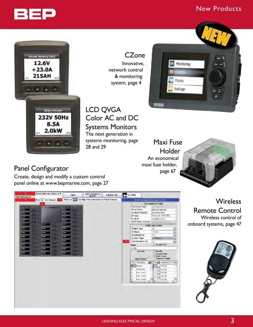
Panel Configurator<br />
Create, design and modify a custom control<br />
panel online at www.bepmarine.com, page 27<br />
<strong>CZone</strong><br />
Innovative,<br />
network control<br />
& monitoring<br />
system, page 4<br />
<strong>LCD</strong> <strong>QVGA</strong><br />
Color AC and DC<br />
Systems Monitors<br />
The next generation in<br />
systems monitoring, page<br />
28 and 29<br />
LEADING ELECTRICAL DESIGN<br />
Maxi Fuse<br />
Holder<br />
An economical<br />
maxi fuse holder,<br />
page 67<br />
New Products<br />
NEW<br />
<strong>Wireless</strong><br />
<strong>Remote</strong> <strong>Control</strong><br />
<strong>Wireless</strong> control of<br />
onboard systems, page 47<br />
3
TRADITIoNAL ELECTRICAL DC WIRING<br />
Wiring DC systems can be complex and installation time can be extensive. The larger the system, the more wire is required, which creates weight and space concerns, not to<br />
mention increased cost and complexity of design and manufacturing. Basic maintenance and trouble shooting of traditional wiring systems can be difficult to manage.<br />
ZONE ONE ZONE TWO ZONE THREE ZONE FOUR<br />
BATTERY<br />
DISTRIBUTION<br />
PANEL<br />
BATTERY BANK<br />
TM<br />
<strong>CZone</strong> Net wor k <strong>Control</strong> and Monitor ing Sys tem<br />
NEW<br />
<strong>CZone</strong> is what you want in a digital control system designed for manufacturers and installers of Marine, RV and Specialty Vehicles. It<br />
simplifies installation of electrical systems through the replacement of complicated, cumbersome wiring to switch and fuse panels, with<br />
state of the art, robust interfaces and light NMEA 2000 network cable. It also provides the the end user a sophisticated solution through<br />
the automation of complicated control and monitoring issues associated with today’s on board systems.<br />
INSTALLATIoN<br />
Builders recognize an immediate benefit with reductions in cable usage, harness weights and installation times. <strong>CZone</strong> also integrates many stand alone components into<br />
one intuitive system. Wiring is dramatically simplified, <strong>CZone</strong> is designed to remove complex switching clusters and wiring runs. Integrated diagnostics ensures fault finding<br />
is simple. <strong>CZone</strong> is the digital networking system that is both cost-effective and scalable. Modules can easily be added into the system to best suit the OEM and end-users’<br />
needs.<br />
CoNFIGuRATIoN<br />
We provide the tools to help you determine the modules needed based on your specific requirements. Then, simply program with the <strong>CZone</strong> intuitive configuration tool.<br />
MAIN DC CIRCUIT<br />
BREAKER PANEL<br />
NEGATIVE<br />
DISTRIBUTION BAR<br />
SWITCH<br />
CONTROL<br />
FOR<br />
LIGHT ONE<br />
DIMMER<br />
TIMER<br />
SWITCH CLUSTER<br />
• Switch panel wiring is complicated and extremely labor intensive to install<br />
• Cable runs are long and have multiple conductors. Switching of common circuits is complex<br />
• Long wire runs require larger cable, adding weight, increasing cost and reducing space<br />
4 LEADING ELECTRICAL DESIGN<br />
TELEVISION<br />
STEREO<br />
ZONE FIVE<br />
FAN<br />
WATER<br />
PUMP<br />
LIGHT<br />
LIGHT
EA 2000<br />
twork<br />
NEW<br />
<strong>CZone</strong> decentralizes the DC power distribution system, locates circuit control and protection modules closer to loads to shorten cable runs and reduce the size of<br />
conductors, significantly decreasing the cost and weight of the electrical wiring harness. The system replaces complex wiring with a single data wire.<br />
BATTERY BANK<br />
• Complex switch panel wiring removed, replaced with single data cable connection<br />
• The grouping of multiple loads into common areas (Zones) with Output Interfaces is the key to the <strong>CZone</strong> system<br />
• Heavy duty battery mains cable, replaced by multiple smaller conductors<br />
LEADING ELECTRICAL DESIGN<br />
<strong>CZone</strong> DC WIRING<br />
ZONE ONE ZONE TWO ZONE THREE ZONE FOUR ZONE FIVE<br />
NMEA 2000<br />
NETWORK<br />
BATTERY<br />
DISTRIBUTION<br />
PANEL<br />
NEGATIVE<br />
DISTRIBUTION<br />
BAR<br />
SWITCH<br />
CONTROL<br />
FOR<br />
LIGHT ONE<br />
SIGNAL<br />
INTERFACE<br />
<strong>CZone</strong> Net wor k <strong>Control</strong> and Monitor ing Sys tem<br />
NMEA<br />
T-Connector<br />
SWITCH<br />
CONTROL<br />
INTERFACE<br />
NMEA<br />
T-CONNECTOR<br />
SWITCH CLUSTER<br />
NMEA 2000<br />
Network<br />
INTEGRATIoN<br />
<strong>CZone</strong> is NMEA 2000 compliant and uses the standard Micro cables and connectors. Being NMEA 2000 compliant you can have<br />
trust in the netwoork. This also allows a single network backbone to be installed for multiple systems (<strong>CZone</strong> and other NMEA 2000<br />
devices). Aditionally, <strong>CZone</strong> can share certain monitoring functions with other NMEA 2000 compliant screens.<br />
VERSATILITy & SECuRITy<br />
<strong>CZone</strong>, designed for 9-32V systems, features built-in timers, dimmers (including support for halogen lighting), alarms, voltage reducers and load shedding. With safety in<br />
mind, <strong>CZone</strong> features a manual bypass. Our No-Single-Failure-Point technology ensures a plug-n-play system that is designed to handle mishaps. If a module is damaged,<br />
the system will automatically program the replacement module, when it is plugged in. This means any module can be replaced without using high tech service people. Our<br />
security features allow custom configurations that can be locked.<br />
OUPUT<br />
INTERFACE<br />
TELEVISION<br />
STEREO<br />
NEGATIVE<br />
DISTRIBUTION BAR<br />
LIGHT<br />
LIGHT<br />
FAN<br />
WATER<br />
PUMP<br />
5<br />
TM
TM<br />
<strong>CZone</strong> Net wor k <strong>Control</strong> and Monitor ing Sys tem<br />
DISPLAy INTERFACE<br />
The <strong>CZone</strong> Display Interface (DI) is the interface between the <strong>CZone</strong> network and the user. It offers full control of circuits as well as the ability to view important on<br />
board systems information such as tank levels and power levels (for both AC and DC supplies), it also provides audiable and visual alarms with systems diagnostics. The DI is<br />
extremely intuitive to use with simple controls and a menu structure that is easy to follow.The “modes of operation” feature allows the control of multiple circuits with a single<br />
push of a button. For instance, “night running” mode turns pre-selected lights on to dim levels. These modes are all user configurable. The DI can be used to set <strong>CZone</strong><br />
parameters for initial installation and future system maintenance.<br />
GENERAL SPECIFICATIoNS:<br />
• 3.5” Transflective <strong>QVGA</strong> <strong>LCD</strong><br />
• IpX7 water ingress Protection<br />
• Rotary Knob for easy menu navigation<br />
• Simple User Interface<br />
• Power consumption @12V: 180mA (standby 130mA)<br />
• H 105mm (4”3/32) x W165mm (6”7/16) x D 62mm<br />
(2”13/32)<br />
PoWER CoNTRoL:<br />
• Turn circuits on and off including timer and light dimming<br />
control (see opposite page for detail)<br />
MoNIToRING:<br />
DC PoWER METER:<br />
• Displays voltages of multiple battery banks, includes low<br />
and high voltage alarms<br />
• Displays charge and discharge (amps) of multiple battery<br />
banks<br />
• Displays battery capacity in ampere hours and % charge/<br />
discharge, includes low ampere hour alarm<br />
AC PoWER METER:<br />
• Displays multiple line voltages (230 and 110V), includes high<br />
and low voltage alarm<br />
• Displays AC line frequencies, includes high and low<br />
frequency alarm and AC power consumption in kW<br />
TANK LEVELS:<br />
• View tank level information for multiple tanks and fluid<br />
types<br />
DATA:<br />
• Displays standard NMEA 2000 information<br />
ALARMS/DIAGNoSTICS<br />
• <strong>CZone</strong> network status reporting<br />
• Presents alarms for on board faults in audible and Visual<br />
form (bilge pump running, smoke alarm)<br />
SET MoDES oF oPERATIoN<br />
CoNTRoL: Breaks down the circuits<br />
into easy to identify groups for quick<br />
control, ie., to turn on fresh water pump<br />
open “pumps” group. User can open<br />
pumps group and select fresh water<br />
pump. This screen also allows the user<br />
to monitor the status of the circuit ie on,<br />
off, fault and current draw.<br />
6 LEADING ELECTRICAL DESIGN<br />
MoNIToRING: Allows user to<br />
easily monitor AC and DC power,<br />
tanks, data, alarms, and circuit status.
<strong>CZone</strong> Net wor k <strong>Control</strong> and Monitor ing Sys tem<br />
The Display Interface is designed with both the manufacturer and end-user in mind. The easy to use display screen puts the control of all components directly at your fingertips.<br />
Multiple Display Interfaces can be used in the same system. The scroll and click interface is simple to use in the roughest of seas or bumpiest of roads. Installation is simple,<br />
bringing all the power of the DI to an area with the simple addition of a power and network cable.<br />
LEADING ELECTRICAL DESIGN<br />
DISPLAy INTERFACE<br />
SETTINGS: Allows OEM or technician access to the configuration (via password) of a<br />
system. No need for computer to set or change configuration settings such as circuit<br />
labels, circuit breaker sizes, etc.<br />
MoDES: Key to the ease of operation. With one key press, user can turn on a group of<br />
circuits, without having to scroll, search for, and turn on the individual circuits that they<br />
need for operation of their vessel/vehicle. When leaving vessel or vehicle, simply press<br />
“systems off” to turn off all non-essential circuits. Entertainment mode allows preset<br />
activation of salon lights, music etc... All functions can be controlled remotely with<br />
<strong>CZone</strong> remote.<br />
PART# DESCRIPTIoN<br />
80-911-0001-00 Display Interface, w/power cable, black bezel<br />
80-911-0002-00 Display Interface, w/power cable, grey bezel<br />
80-911-0003-00 Display Interface only, black<br />
80-911-0004-00 Display Interface only, grey<br />
2- pin Power Connector NMEA 2000 Connector<br />
7<br />
TM
TM<br />
<strong>CZone</strong> Net wor k <strong>Control</strong> and Monitor ing Sys tem<br />
SWITCH CoNTRoL INTERFACE<br />
The Switch <strong>Control</strong> Interface (SCI) provides an interface between the<br />
<strong>CZone</strong> network and traditional mechanical switches that manufacturers and<br />
users are familiar with. This interface converts the signal from those switches<br />
into the <strong>Control</strong> Area Network (CAN) signal needed across a digital network.<br />
No need to change existing designs.<br />
Diagnostics are important. Fault codes are provided to quickly identify issues<br />
with the network or switches. Information is provided on the Switch <strong>Control</strong><br />
Interface as well as sent to the <strong>CZone</strong> Display Interface.<br />
The SCI simplifies your wiring, supports your existing choice of switches,<br />
protects against failures and allows for expanding installation options.<br />
Backlighting and systems in operation lights are dimmable to ensure your night<br />
vision is not impared by bright lights on your control area, level control of<br />
these can be linked to the backlighting level of any Display Interfaces in close<br />
proximity of the SCI.<br />
GENERAL SPECIFICATIoNS:<br />
• Single switch position can control<br />
multiple OI channels<br />
• Attaches to switch panels via<br />
custom SCI cable<br />
• Multiple SCI switches can control<br />
single OI channel<br />
• Output for backlighting of switch<br />
labels (dimmable)<br />
• Outputs systems on and function/<br />
fault codes to systems on LED of<br />
switches (dimmable)<br />
• H 100mm (3”29/ 32) x W156mm<br />
(6”3/ 32) x D 42mm (1”5/ 8)<br />
• IPX5 water ingress protection<br />
• Programmable switch types<br />
• 8 inputs per module (16 individual<br />
controls)<br />
• Sequential button press<br />
functionality<br />
8-Way Connector Bank for SCI<br />
Cable Assembly to Switches<br />
Waterproof Cable Seal<br />
8 LEADING ELECTRICAL DESIGN<br />
PART# DESCRIPTIoN<br />
80-911-0011-00 Switch <strong>Control</strong> Interface w/seal<br />
80-911-0012-00 Switch <strong>Control</strong> Interface only<br />
NMEA 2000 Connector
SIGNAL INTERFACE<br />
The Signal Interface (SI) connects <strong>CZone</strong> to your external sensors, alarms<br />
and switching devices. The SI allows intelligent, automated operation of<br />
circuits depending on the state of the input. For example, the SI can be<br />
easily programmed to allow a fluid transfer pump and an alarm to turn on<br />
simultaneously when the SI detects that a low tank level has been reached.<br />
Connect standard switches to the SI to allow control of <strong>CZone</strong> outputs.<br />
The module provides LED status indications for each input. This allows fast<br />
diagnostics while providing information back to <strong>CZone</strong>’s Display Interface.<br />
GENERAL SPECIFICATIoNS:<br />
• Accepts inputs from traditional<br />
switch types being used to control<br />
outputs<br />
• Accepts inputs from switches to<br />
trigger alarm i.e. high water float<br />
switch<br />
• Accepts inputs from industry<br />
standard tank senders (0-5V, 10-<br />
180Ohm, 240-33Ohm)”<br />
• Accepts inputs from general<br />
voltaic or resistive signals can be<br />
used for controlling outputs or to<br />
display a physical position i.e. show<br />
a hatch is partially open<br />
• LED status indicators for each<br />
input<br />
• H 100mm (3”29/32) x W156mm<br />
(6”3/32) x D 42mm (1”5/8)<br />
• IPX5 water ingress protection<br />
Terminal Block<br />
<strong>CZone</strong> Net wor k <strong>Control</strong> and Monitor ing Sys tem<br />
Signal<br />
Status<br />
Indicator<br />
Waterproof Cable Seal<br />
LEADING ELECTRICAL DESIGN<br />
PART# DESCRIPTIoN<br />
80-911-0013-00 Signal Interface w/seals, connector<br />
80-911-0014-00 Signal Interface only<br />
CAN Network Status Indicator<br />
NMEA 2000 Connector<br />
9<br />
TM
METER INTERFACE<br />
The Meter Interface (MI) accepts inputs from external AC and DC power<br />
metering sensors. It then processes and converts the analog signals into<br />
digital strings that can then be presented, by the display, to the user, as one of<br />
several, easy-to-understand formats such as:<br />
AC and DC voltage and amps<br />
AC Kilowatts<br />
DC battery capacity in amp hours and % remaining<br />
All with user definable high and low alarms<br />
Intelligence is built into <strong>CZone</strong>. The MI can calculate the battery capacity<br />
as ampere hours and/or percentage of charge remaining. Since <strong>CZone</strong><br />
provides both monitoring and control for DC systems, it can be configured to<br />
turn off non-essential circuits in the event that the battery is discharged to a<br />
low level. This helps to ensure that there is enough charge left in the battery<br />
to power safety critical circuits.<br />
GENERAL SPECIFICATIoNS:<br />
AC<br />
• 3 x AC voltage inputs (multi<br />
voltage)<br />
• 2 x AC current inputs<br />
• Calculates true RMS power<br />
• Ignition protected<br />
TM<br />
<strong>CZone</strong> Net wor k <strong>Control</strong> and Monitor ing Sys tem<br />
DC<br />
• 3 x DC voltage inputs (multi<br />
voltage)<br />
• 2 x DC current inputs<br />
• Calculates battery capacity as<br />
Ampere hours and percentage<br />
charge remaining<br />
• Resolution for current metering<br />
down to 0.1A<br />
GENERAL<br />
• H 100mm (3”29/32) x W156mm<br />
(6”3/32) x D 42mm (1”5/8)<br />
• IPX5 water ingress protection<br />
Note: High and low alarm levels<br />
can be set for all inputs<br />
Terminal Block<br />
Waterproof Cable Seal<br />
AC Voltage<br />
Indicator<br />
DC Voltage<br />
Indicator<br />
Network<br />
Status Indicator<br />
10 LEADING ELECTRICAL DESIGN<br />
PART# DESCRIPTIoN<br />
80-911-0005-00 Meter Interface, w/seal & plug<br />
80-911-0006-00 Meter Interface only<br />
NMEA 2000 Connector
ouTPuT INTERFACE<br />
The Output Interface (OI) provides an intelligent replacement for traditional<br />
circuit breaker and fuse panels. It has 6x high power, robust output channels<br />
which provide the power supply, control and fusing for a circuit as well as<br />
integrating many other built in features such as timers and dimmers.<br />
The OI is behind the <strong>CZone</strong> concept of decentralising the power<br />
distribution, compared to a traditional electrical layouts which are typically<br />
based around a large, centralised circuit breaker or fuse panel. The OI’s allow<br />
the installer to move the circuit control and protection closer to the loads<br />
which significantly shortens cable runs and reduces the size of the conductors.<br />
This equates to a reduction in the cost and weight of the electrical wiring<br />
harness, ie. less copper.<br />
Connection to the unit is simple: a large 6 way plug allows connections to<br />
cables of up to 16mm 2 (6AWG) in size, or multiple smaller conductors. No<br />
need for specialised crimp terminals and expensive crimp tools to be carried<br />
for terminations to <strong>CZone</strong>, just a blade screwdriver. A protective flexible<br />
boot offers protection to the connections from harsh environment conditions.<br />
GENERAL SPECIFICATIoNS:<br />
• 4 levels of backup fusing including<br />
manual override (as required by<br />
ABYC)<br />
• 6 x 20 amp circuits<br />
• Programmable software “fuse”<br />
sizes<br />
• Multiple channels can be bridged<br />
together to offer higher current<br />
switching<br />
• Small, non metallic, easy to install<br />
case<br />
• IPX5 water ingress protection<br />
• Dimensions: H 128mm (5”) x<br />
W200mm (7”29/32) x D 45mm<br />
(1”3/4)<br />
• Power consumption @12V: 85mA<br />
(standby 60mA)<br />
DC Positive Feed<br />
Connector & Protective Boot<br />
<strong>CZone</strong> Net wor k <strong>Control</strong> and Monitor ing Sys tem<br />
Fuses For Emergency<br />
Circuit Bypass<br />
LEADING ELECTRICAL DESIGN<br />
PART# DESCRIPTIoN<br />
80-911-0009-00 Output interface w/connector, boot<br />
80-911-0010-00 Output interface only<br />
Circuit ID Label<br />
Circuit Status<br />
Indicator<br />
NMEA 2000 Connector<br />
11<br />
TM
TM<br />
<strong>CZone</strong> Net wor k <strong>Control</strong> and Monitor ing Sys tem<br />
MoToR ouTPuT INTERFACE<br />
The Motor Output Interface (MOI) has an output pair for controlling DC<br />
motors which require a reversal of polarity to change the direction of their<br />
mechanical operation. For example, a DC motor for an electric window<br />
mechanism will move the window up or down depending on the polarity of the<br />
feed to the motor.<br />
Historically the wiring and control circuitry for such installations is complicated<br />
and requires a number of individual components, often controls for these<br />
devices are mounted remotely to the motor so wiring runs can be long. the<br />
MOI replaces all of these devices with one simple solution that can be mounted<br />
close to the motor further reducing cable runs.<br />
The MOI can be configured to deliver a “soft start” so that motor driven<br />
devices don’t start with a sudden and abrupt motion.<br />
The MOI also incorporates two standard output channels such as is found on<br />
the OI.<br />
GENERAL SPECIFICATIoNS:<br />
• Single motor control and two<br />
normal channels per unit, 20A<br />
per output<br />
• Built In circuit protection<br />
• IPX5 water ingress protection<br />
• Dimensions: H 128mm (5”) x<br />
W200mm (7”29/32) x D 45mm<br />
(1”3/4)<br />
Fuses For<br />
Emergency<br />
Circuit Bypass<br />
Connector & Protective Boot<br />
Reverse Polarity<br />
Indicator<br />
12 LEADING ELECTRICAL DESIGN<br />
PART# DESCRIPTIoN<br />
80-911-0007-00 Motor Output Interface w/connector, boot<br />
80-911-0008-00 Motor Output Interface only<br />
Network Status<br />
indicator<br />
NMEA 2000 Connector
Historically, generating a configuration for and programming a system<br />
is a chore that requires a significant amount of training. The <strong>CZone</strong>’s<br />
configuration tool offers simple, straightforward programming that is<br />
easy to learn and to use.<br />
The <strong>CZone</strong> Configuration Tool allows the manufacturer to set<br />
up programming parameters on a standard PC, (use USB CAN<br />
Adapter# 80-911-0044-00) upload a saved configuration into the<br />
<strong>CZone</strong> network and simultaneously program every interface onboard.<br />
Changes and customizations can also be made from the Display<br />
Interface and downloaded back to the PC overriding the master<br />
configuration. The master template file is now ready to go and can be<br />
used on multiple vessels or vehicles during manufacturing.<br />
<strong>CZone</strong> Net wor k <strong>Control</strong> and Monitor ing Sys tem<br />
LEADING ELECTRICAL DESIGN<br />
CoNFIGuRATIoN MADE EASy<br />
13<br />
TM
TM<br />
<strong>CZone</strong> Net wor k <strong>Control</strong> and Monitor ing Sys tem<br />
<strong>CZone</strong> ACCESSoRIES<br />
NMEA 2000 Ext. Cable<br />
# 80-911-0024-00 15 ft 4.57meters<br />
# 80-911-0025-00 25 ft 7.62 meters<br />
# 80-911-0026-00 2 ft .61 meters<br />
# 80-911-0027-00 6 ft 1.82 meters<br />
uSB CAN Adapter<br />
# 80-911-0044-00<br />
• Connects PC to the CZONE network<br />
for configuration and system set up<br />
AC-VSEN-4<br />
The AC-VSEN-4 includes 3 voltage transformers for<br />
up to 3 voltage inputs.<br />
Dimensions: 69 x 140 x 50 mm (2.75 x 5.5 x 2 in)<br />
NMEA 2000 Power Cable<br />
# 80-911-0028-00 3.2 ft 1 meter<br />
NMEA 2000 T-Piece<br />
# 80-911-0029-00<br />
CT-10-3<br />
Dimensions: 37.5 x 39.2 x 13.7 mm<br />
(1.5 x 1.55 x .55 in)<br />
Hole size: 12 mm (0.5”)<br />
14 LEADING ELECTRICAL DESIGN<br />
Power Cable for<br />
Display Interface, 2 Pin, 2 meters<br />
# 80-911-0032-00 6.5 ft 2 meters<br />
<strong>CZone</strong> <strong>Wireless</strong> <strong>Remote</strong> Kit<br />
#80-911-0045-00<br />
• A simple to set up, wireless remote control<br />
• Configure the buttons to operate Individual<br />
circuits or to control multiple circuits through<br />
a mode of operation<br />
CT-HD<br />
CT-HD is available for systems with large mains<br />
cables, too large for CT-10-3 (ordered separately).<br />
CT-HD dimensions: Ø 47 x 10.5 mm<br />
(Ø 1.85 x 0.4 in)<br />
Hole size: 32 mm (1.25 in)
Cable Gland for SCI Blk Silicon<br />
# 80-911-0035-00<br />
Cable Gland, SI, Blk Silicon<br />
# 80-911-0036-00<br />
Cable Gland, MI Blk Silicon<br />
# 80-911-0033-00<br />
Hole Plugs, Blk<br />
# 80-911-0016-00 3.2mm<br />
# 80-911-0017-00 5 mm<br />
3.2mm for MI and SI cable glands<br />
5mm for SCI cable glands<br />
NMEA 2000 Resistors<br />
# 80-911-0030-00 Female<br />
# 80-911-0031-00 Male<br />
<strong>CZone</strong> Net wor k <strong>Control</strong> and Monitor ing Sys tem<br />
Terminal Block for MI, 6 Way<br />
# 80-911-0042-00<br />
LEADING ELECTRICAL DESIGN<br />
<strong>CZone</strong> ACCESSoRIES<br />
Terminal Block, SI/MI 8W<br />
# 80-911-0043-00<br />
Terminal Block, OI/MOI, 6W<br />
# 80-911-0041-00<br />
Seal Boot for oI/MoI ,<br />
6-Wire, Blk Silicon<br />
# 80-911-0034-00<br />
Cable Assembly, SCI<br />
to suit Switches below<br />
# 80-911-0018-00 .5 meter<br />
# 80-911-0019-00 1 meter<br />
# 80-911-0020-00 2 meter<br />
# 80-911-0021-00 3 meter<br />
# 80-911-0022-00 4 meter<br />
# 80-911-0023-00 5 meter<br />
Custom Switches<br />
# 80-911-0037-00 ON/OFF<br />
# 80-911-0038-00 mom ON/OFF<br />
# 80-911-0039-00 ON/OFF/ON<br />
# 80-911-0040-00 mom ON/OFF/mom ON<br />
15<br />
TM
Circuit Breaker Panels<br />
DC no meter s<br />
Range HigHligHts<br />
Red systems on LED<br />
Marine grade powder coated<br />
aluminium<br />
ABYC standard voltage indication<br />
Green LED backlit labels<br />
Airpax Circuit Breakers<br />
Stylish clip on contour fascia<br />
Label sets and buss bar supplied<br />
with panels; for additional labels<br />
see pages 71 and 72<br />
904NM<br />
DC <strong>Control</strong> Panels - No Meters, 12 V<br />
Part No. mm<br />
in Label CB's - Single Pole Neg Bus<br />
H x W x 65 H x W x 2.5 Sheet 5 10 15 20 25 30<br />
900 115 x 127 4.5 x 5 1 1 2 1 6 way<br />
901H 115 x 239 4.5 x 9.75 " 2 2 3 1 "<br />
901V 200 x 127 7.9 x 5 " 2 2 3 1 "<br />
902NMH 115 x 351 4.5 x 13.9 " 3 4 4 1 "<br />
902NMV 285 x 127 11.25 x 5 " 3 4 4 1 "<br />
904NM 200 x 239 7.9 x 9.75 " 4 5 5 1 1 12 way<br />
904NMH 115 x 463 4.5 x 18.25 " 4 5 5 1 1 "<br />
904NMV 370 x 127 14.6 x 5 " 4 5 5 1 1 "<br />
905NM 200 x 351 7.9 x 13.9 1 - 3 5 8 8 1 1 1 "<br />
905NMV 285 x 239 11.25 x 9.75 " 5 8 8 1 1 1 "<br />
906NMH 200 x 463 7.9 x 18.25 1 - 4 7 11 11 1 1 1 24 way<br />
906NMV 370 x 239 14.6 x 9.75 " 7 11 11 1 1 1 "<br />
NC36NM 285 x 351 11.25 x 13.9 1 - 4, 6 8 12 12 2 1 1 "<br />
Cutout size - 10 mm (3/8 in) inside all external edges<br />
All panels available in 12 or 24 V configuration. All part numbers shown are 12 V backlighting.<br />
If 24 V is required, please specify when ordering.<br />
16 LEADING ELECTRICAL DESIGN<br />
901V<br />
902NMV<br />
902NMH<br />
901H<br />
900<br />
904NMV
905NM<br />
NC36NM<br />
904NMH<br />
906NMH<br />
LEADING ELECTRICAL DESIGN<br />
Circuit Breaker Panels<br />
DC no meter s<br />
905NMV<br />
906NMV<br />
17
Circuit Breaker Panels<br />
DC analog/digital meter s<br />
900A<br />
901DV<br />
902A-12V<br />
DC <strong>Control</strong> Panels - Digital Meters<br />
Part No. mm<br />
in Label CB's - Single Pole Neg Bus<br />
L x W x 65 H x W x 2.5 Sheet 5 10 15 20 25 30<br />
900D 200 x 127 7.9 x 5 1 1 2 1 6 way<br />
901DV 295 x 127 11.6 x 5 " 2 2 3 1 "<br />
902D 200 x 239 7.1 x 9.75 " 3 4 4 1 "<br />
902DV 380 x 127 15 x 5 " 3 4 4 1 "<br />
903D 200 x 351 7.9 x 9.75 1 - 3 5 6 7 1 1 12 way<br />
904D 295 x 239 11.6 x 9.75 1 - 2 4 5 5 1 1 "<br />
905D 295 x 351 11.6 x 13.9 1 - 3 5 8 8 1 1 1 "<br />
905DV 380 x 239 15 x 9.75 " 5 8 8 1 1 1 "<br />
906D 295 x 463 11.6 x 18.25 1 - 4 7 11 11 1 1 1 24 way<br />
906DV 455 x 239 18 x 9.75 " 7 11 11 1 1 1 "<br />
907D-24V 380 x 463 15 x 18.25 1 - 5 12 15 15 3 1 2 2 x 24 way<br />
18 LEADING ELECTRICAL DESIGN<br />
903D<br />
904A-12V<br />
905A-12V 905DV<br />
902DV
906A<br />
907A<br />
LEADING ELECTRICAL DESIGN<br />
Circuit Breaker Panels<br />
DC analog/digital meter s<br />
Range HigHligHts<br />
Ammeters available in other scales<br />
(page 26).<br />
All panels are available with either<br />
Analog or Digital meters<br />
Label set and bus bar supplied with<br />
panel; for additional label sets see<br />
pages 71 and 72<br />
906AV<br />
DC <strong>Control</strong> Panels - Analog Meters<br />
Part No. mm<br />
in Label CB's - Single Pole Neg Bus<br />
H x W x 65 H x W x 2.5 Sheet 5 10 15 20 25 30<br />
900A 200 x 127 7.9 x 5 1 1 2 1 6 way<br />
901AV-12V 295 x 127 11.6 x 5 " 2 2 3 1 "<br />
902A-12V 200 x 239 7.9 x 9.75 " 3 4 4 1 "<br />
902AV-12V 380 x 127 15 x 5 " 3 4 4 1 "<br />
903A 200 x 351 7.9 x 9.75 1 - 3 5 6 7 1 1 12 way<br />
904A-12V 295 x 239 11.6 x 9.75 1 - 2 4 5 5 1 1 "<br />
905A-12V 295 x 351 11.6 x 13.9 1 - 3 5 8 8 1 1 1 "<br />
905AV 380 x 239 15 x 9.75 " 5 8 8 1 1 1 "<br />
906A 295 x 463 11.6 x 18.25 1 - 4 7 11 11 1 1 1 24 way<br />
906AV 455 x 239 18 x 9.75 " 7 11 11 1 1 1 "<br />
907A 380 x 463 15 x 18.25 1 - 5 12 15 15 3 1 2 2 x 24 way<br />
All analog panels supplied with one shunt, extra shunts ordered separately. Digital panels supplied<br />
with 450 A-50mV shunt.<br />
Cutout size - 10 mm (3/8 in) inside all external edges<br />
All panels available in 12 or 24 V configuration. All part numbers shown are 12 V backlighting.<br />
If 24 V is required, please specify when ordering.<br />
19
Circuit Breaker Panels<br />
Cr uiser Ser ies<br />
Range HigHligHts<br />
Mimic panel for quick reference of<br />
systems in operation<br />
Blank space for addition of extra<br />
meter eg: tank monitor<br />
Digital or analog readouts<br />
DC <strong>Control</strong> Panels - Cruiser Series, 24 Way, 12 V<br />
Part No. mm<br />
in Label Sheet CB's - Single Pole Meter<br />
H x W x 65 H x W x 2.5<br />
5 10 15 20 25 30<br />
NC32YD 380 x 351 15 x 13.9 1 - 4, 6 7 11 11 1 1 1 Digital<br />
NC36LD 380 x 351 15 x 13.9 " 8 12 12 2 1 1 Digital<br />
NC32YA 380 x 351 15 x 13.9 " 7 11 11 1 1 1 Analog<br />
NC36LA 380 x 351 15 x 13.9 " 8 12 12 2 1 1 Analog<br />
All analog panels supplied with one shunt, extra shunts ordered separately. Digital panels supplied with 450A – 50mV shunt.<br />
Cutout size - 10 mm (3/8 in) inside all external edges<br />
All panels available in 12 or 24 V configuration. If 24 V is required, please spcify when ordering,<br />
Range HigHligHts -<br />
DP Panel<br />
Double pole panels available in all<br />
panel sizes.<br />
Double pole CBs use twice the<br />
space of single pole breakers; an<br />
8-way panel can become a 4-way<br />
AC or DC versions available<br />
Single toggle<br />
NC36LD NC32yD<br />
20 LEADING ELECTRICAL DESIGN<br />
DP PANEL
M44D<br />
M32D<br />
M28D<br />
LEADING ELECTRICAL DESIGN<br />
Circuit Breaker Panels<br />
Compact sizing<br />
Millenium Ser ies<br />
Range HigHligHts -<br />
MillenniuM Range<br />
Battery monitoring using BEP<br />
multifunction meter (voltage on 3<br />
battery banks, charge, discharge<br />
amps and amp-hours remaining on<br />
main battery bank (see 600-DCM<br />
page 30)<br />
M44DH M56D<br />
DC <strong>Control</strong> Panels - Millennium Range, 24 Way, 12 V<br />
Part No. mm<br />
in Label CB's - Single Pole Meter<br />
H x W x 65 H x W x 2.5 Sheet 5 10 15 20 25 30<br />
M28D 370 x 239 14.6 x 9.75 1 - 4 8 8 8 2 2 Digital<br />
M32D 285 x 351 11.25 x 13.9 1 - 4, 6 7 11 11 1 1 1 "<br />
M44D 370 x 351 14.6 x 13.9 " 10 14 14 3 1 2 "<br />
M44DH 285 x 463 11.25 x 18.25 " 10 14 14 3 1 2 "<br />
M56D 455 x 351 18 x 13.9 " 12 18 18 4 2 2 "<br />
21
AC Circuit Breaker Panels<br />
No meter s<br />
REVERSE PoLARITy<br />
AuTo TRIP BREAKER<br />
NoW STANDARD on<br />
all 230 V, 50 Hz panels<br />
(Euro and Asia-Pacific).<br />
This will automatically trip<br />
when it detects reverse<br />
polarity.<br />
900-ACM2W<br />
CBS-20A-DP-TC230<br />
900-AC1<br />
For standard twin<br />
input systems, eg:<br />
one shore power<br />
and one genset<br />
input.<br />
22 LEADING ELECTRICAL DESIGN<br />
Range HigHligHts<br />
Ideal for AC shore power<br />
installations and on board inverter<br />
installations.<br />
900-ACM6W<br />
900-ACCH<br />
AC <strong>Control</strong> Panels - No Meters<br />
Part No. Volts mm<br />
in Label CB's - Single Pole CB's - Double Pole Neg Bus<br />
H x W x 65 H x W x 2.5 Sheet 5 10 15 20 25 30 20 25 30 50 80<br />
900-ACM2WA 230 115 x 239 4.5 x 9.75 5 2 2 2 IS-6MM-2<br />
900-AC1-110V 110 115 x 239 4.5 x 9.75 5 2 2 2 IS-6MM-2<br />
900-ACM2W 230 115 x 127 4.5 x 5 5 2 1 IS-6MM-2<br />
900-ACM2W-110V 110 115 x 127 4.5 x 5 5 2 1 IS-6MM-2<br />
900-ACM6W 230 200 x 127 7.9 x 5 5 2 3 1 1 IS-6MM-2<br />
900-ACM6W-110V 110 200 x 127 7.9 x 5 5 3 2 1 1 IS-6MM-2<br />
900-ACCH 230 115 x 127 7.9 x 5 5 2 IS-6MM-2<br />
900-ACCH-110V 110 115 x 127 7.9 x 5 5 2 IS-6MM-2
Range HigHligHts<br />
All available in 110 V/60 Hz or<br />
230 V/50 Hz<br />
All supplied with tranducers<br />
Reverse polarity indicator<br />
Double pole mains input CBs with<br />
slde lockout<br />
Digital meter shows volts, amps<br />
and frequency<br />
LED wired to indicate live panel<br />
with mains breaker either on or off<br />
AC source selector ensures no<br />
cross over between AC inputs<br />
(ship or shore power)<br />
AC voltage/frequency label to<br />
comply with ABYC Standards<br />
Reverse polarity auto trip breakers are used as standard<br />
for shore power mains inputs (230 V AC panels only)<br />
900-ACMA2W 900-AC2AH 900-AC4D<br />
AC <strong>Control</strong> Panels - Analog Meters<br />
Part No. Volts mm in Label CB's - Single Pole CB's - Double Pole Neg Bus<br />
H x W x 65 H x W x 2.5 Sheet 5 10 15 20 25 30 20 25 30 50 80<br />
900-ACMA2W 230 200 x 127 7.9 x 5 5 2 2 IS-6MM-2<br />
900-ACMA2W-110V 110 200 x 127 7.9 x 5 5 2 1 IS-6MM-2<br />
900-ACM6WA-V 230 295 x 127 11.6 x 5 5 2 3 1 1 IS-6MM-2<br />
900-ACM6WA-V-110V 110 295 x 127 11.6 x 5 5 1 3 3 1 1 1 IS-6MM-2<br />
900-AC2AH 230 200 x 239 7.9 x 9.75 5 1 3 3 1 1 1 2 x 6 way<br />
900-AC2AH-110V 110 200 x 239 7.9 x 9.75 5 2 3 2 1 1 1 2 x 6 way<br />
900-AC2AV 230 380 x 127 15 x 5 5 1 3 3 1 1 1 2 x 6 way<br />
900-AC2AV-110V 110 380 x 127 15 x 5 5 1 2 3 2 1 1 1 2 x 6 way<br />
900-AC3A 230 200 x 351 7.9 x 13.9 5 1 4 5 1 1 1 1 2 x 12 way<br />
900-AC3A-110V 110 200 x 351 7.9 x 13.9 5 1 3 4 3 1 1 1 1 2 x 12 way<br />
AC <strong>Control</strong> Panels - Digital Meters<br />
900-AC2DH 230 200 x 239 7.9 x 9.75 5 1 3 3 1 1 1 2 x 6 way<br />
900-AC2DH-110V 110 200 x 239 7.9 x 9.75 5 2 3 2 1 1 1 2 x 6 way<br />
900-AC2DV 230 380 x 127 15 x 5 5 1 3 3 1 1 1 2 x 6 way<br />
900-AC2DV-110V 110 380 x 127 15 x 5 5 1 2 3 2 1 1 1 2 x 6 way<br />
900-AC3D 230 200 x 351 7.9 x 13.9 5 1 4 5 1 1 1 1 2 x 12 way<br />
900-AC3D-110V 110 200 x 351 7.9 x 13.9 5 1 3 4 3 1 1 1 2 x 6 way<br />
900-AC4D 230 200 x 351 7.9 x 13.9 5 1 5 7 2 1 1 1 2 x 6 way<br />
900-AC4D-110V 110 200 x 351 7.9 x 13.9 5 5 8 2 1 1 1 2 x 6 way<br />
Cutout size - 10 mm (3/8 in) inside all external edges<br />
All panels available in 12 or 24 V backlighting configuration. For 110 V versions add -110V to Part No.<br />
LEADING ELECTRICAL DESIGN<br />
AC Circuit Breaker Panels<br />
Analog/digital meter s<br />
900-AC3D<br />
900-ACM6WA-V<br />
900-AC2DV<br />
23
AC Circuit Breaker Panels<br />
Back Cover s/RCDs<br />
Range HigHligHts<br />
Designed to insulate exposed rear<br />
terminals<br />
Flame retardant PVC in two styles<br />
FLANGE MOUNT: for access to<br />
control panel back when mounted<br />
in place. Attaches to the rear of<br />
the same mounting surface as the<br />
panel<br />
PANEL MOUNT: for access only<br />
when panel is removed. Supplied<br />
with mounting pedestals<br />
AC Back Panel Covers<br />
Part No. Mount Cover description mm in<br />
type<br />
L x W x 90 L x W x 3.5<br />
BC-FM1 Flange 1 column 8-12 CBs + meter 380 x 127 15 x 5<br />
BC-FM2 Flange 2 column 8-12 CBs + meter 380 x 239 15 x 9.4<br />
BC-FM3 Flange 1 column 8-12 CBs 285 x 127 15 x 5<br />
BC-FM4 Flange 2 column 8-12 CBs 285 x 239 15 x 9.4<br />
BC-PM1 Panel 1 column 8-12 CBs + meter 360 x 107 15 x 4.2<br />
BC-PM2 Panel 2 column 8-12 CBs + meter 360 x 219 15 x 8.6<br />
BC-PM3 Panel 1 column 8-12 CBs 265 x 107 15 x 4.2<br />
Range HigHligHts -<br />
We supply two Residual Current<br />
Device (RCD) ratings (16 & 32 A).<br />
Due to the difference in style of the<br />
RCD’s, these panels are made to be<br />
mounted separately from the main<br />
AC panel.<br />
24 LEADING ELECTRICAL DESIGN<br />
Part No.<br />
RCD Panels<br />
Rating (A) mm in<br />
H x W x 65 H x W x 2.5<br />
900-RCD-16A 16 115 x 127 4.5 x 5<br />
900-RCD-1X16-32A 32 115 x 127 4.5 x 5<br />
900-RCD-2X16A 16x2 115 x 127 4.5 x 5<br />
900-RCD-2X32A 32x2 115 x 127 4.5 x 5<br />
900-RCD-32A 16x1, + 32x1 115 x 127 4.5 x 5<br />
Cutout size - 10 mm (3/8 in) inside all external edges<br />
For installations in Australia and New Zealand to comply with AS/NZ3004 an approved double pole mains circuit breaker must be mounted upstream of the<br />
BEP <strong>Control</strong> Panel in the form of a RCD or MCB. The MCB-3WENC is an enclosure with IP65 rating. The enclosure and CB is ordered separately. The RCD<br />
panels above can also be used for this application, however they would have to be mounted in a dry protected position on the vessel.<br />
Dimensions of MCB-3WENC:<br />
160 mm (6.3”) H x<br />
92 mm (3.6”) W x<br />
90 mm (3.5”) D<br />
900-RCD-16A<br />
900-RCD-2X16A<br />
MCB-3WENC RCD (see chart) MCB (see chart)<br />
BC-PM1<br />
BC-FM2<br />
BC-FM1<br />
BC-PM2<br />
Part No.<br />
CB options<br />
Rating (A) Type<br />
RCD16A30MA 16 Residual CB Overload<br />
RCD32A30MA 32 Residual CB Overload<br />
RCD63A30MA 63 Residual CB<br />
MCB16A 16 Miniature CB<br />
MCB32A 32 Miniature CB<br />
MCB63A 63 Miniature CB
Range HigHligHts<br />
Spacing compliance: IEC<br />
specification 601, 950; VDE 0804,<br />
0805<br />
UL recognized; CSA certified; VDE<br />
0660 approved; Part 101 & CE<br />
compliant<br />
Available in single or double pole;<br />
triple pole available on special<br />
orders<br />
NoTE: Part numbers shown are all<br />
BEP specific and have no reference<br />
to the Airpax part number system.<br />
IEG Magnetic CBs<br />
IEG magnetic circuit breakers provide reliable<br />
circuit protection and accurate circuit control for<br />
equipment in the international market place.<br />
Designed using the latest in sensitive hydraulic<br />
magnetic technology, the IEG line adapts itself to<br />
many applications and environments. They are ideal<br />
for marine applications, data processing and business<br />
CBS-50A-SP-IGP<br />
Single Toggle 1-2 & 3 Pole Small Frame<br />
Single pole Rating (A) Double pole Rating Triple pole / Rating Rating (A)<br />
(A)<br />
(A)<br />
CBS-2.5A-SP 2.5 CBS-2.5A-DP 2.5 CBS-30A-TP / 30 30<br />
CBS-5A-SP 5 CBS-5A-DP 5 CBS-50A-TP / 50 50<br />
CBS-10A-SP 10 CBS-10A-DP 10 D/Pole trip coil Volts (V)<br />
CBS-15A-SP 15 CBS-15A-DP 15 CBS-15A-DP-TC230 230<br />
CBS-20A-SP 20 CBS-20A-DP 20 CBS-20A-DP-TC230 230<br />
CBS-25A-SP 25 CBS-25A-DP 25 CBS-30A-DP-TC230 230<br />
CBS-30A-SP 30 CBS-30A-DP 30 CBS-50A-DP-TC230 230<br />
CBS-40A-SP 40 CBS-40A-DP 40<br />
CBS-50A-SP 50 CBS-50A-DP 50<br />
Single Toggle 1-2 & 3 Pole Large Frame<br />
Single pole Rating (A) Double pole Rating<br />
(A)<br />
Triple pole Rating (A)<br />
CBL-50A-SP 50 CBL-50A-DP 50 CBL-50A-TP 50<br />
CBL-60A-SP 60 CBL-60A-DP 60 CBL-80A-TP 80<br />
CBL-75A-SP 75 CBL-75A-DP 75 CBL-100A-TP 100<br />
CBL-100A-SP 100 CBL-100A-DP 100<br />
LEADING ELECTRICAL DESIGN<br />
Circuit Breakers<br />
Tog gles<br />
machines, as well as medical instrumentation,<br />
broadcast equipment, vending and amusement<br />
machines, military applications and wherever<br />
precision operation is required. Temperature<br />
differences which affect fuses and other thermal<br />
devices are not a concern. One important feature of<br />
this breaker line is a ‘trip free’ action, which means<br />
the circuit will trip in the presence of an overload<br />
even though the handle is held in the ON position.<br />
The delay mechanism senses the fault and the<br />
contacts open.<br />
CBS-50A-DP<br />
121-710-1101<br />
Image shows “handle lock” as used in all our battery management panels for essential CBs<br />
to prevent accidental or unintended actuation of essential circuits CB’s from either the<br />
“on” or “off” position. (ordered separately)<br />
IuL Magnetic CBs<br />
provide reliable<br />
circuit protection and<br />
accurate circuit control<br />
for equipment in the<br />
international market place.<br />
BEP uses the IUL range<br />
CBL-50A-SP<br />
121-710-1101/1<br />
of circuit breakers where<br />
current requirements<br />
exceed 50 A and are within<br />
100 A. Available in single<br />
and double pole with triple<br />
pole available on special<br />
orders.<br />
CBL-100A-DP<br />
25
Circuit Breakers<br />
Heav y Duty/Push to Reset<br />
Single Pole Thermal Type Breakers<br />
Ratings: 50 A to 150 A; 30 V DC, 3000 A<br />
interrupt capacity<br />
operating Temperature: -25°F (-32°C) to 180°F (82°C)<br />
Storage Temperature: -30°F (-34°C) to 300°F (149°C)<br />
Applications: Auxiliary and accessory circuits – trucks,<br />
buses, RVs and marine applications,<br />
battery chargers and DC audio systems.<br />
Series 181, 184 & 185 are sealed for<br />
engine compartment and bilge area<br />
applications.<br />
Housing: Thermoset plastic; UL rated 94VO;<br />
311ºF (155ºC). Stud insulators are<br />
200%<br />
TEMPERATURE provided on DERATING covered units CURVES with F<br />
(Surface Mount) bases<br />
Mounting:<br />
150%<br />
Panel or surface<br />
Indicator: Series 184 & 185 have a unique reset<br />
100% mechanism providing visible indication<br />
of tripped condition<br />
Approvals:<br />
50%<br />
0%<br />
Complies with SAEJ1625<br />
TEMERATURE IN DEGREES F.<br />
% OF RATED CURRENT<br />
Busmann ® Heavy Duty<br />
Carling CLB Series Push Reset Thermal Circuit Breakers<br />
Specifications:<br />
Ratings: 5—40 A; 200 A @ 250 V AC Interrupt<br />
Capacity<br />
Operating Temperature: -10—60° C<br />
Interrupting capacity: 2500 A<br />
Ressettable overload capacity: 10 x rated current<br />
Approvals: UL, CUL, TUV, CE, UL1500ISO8846 for<br />
ignition protection/marine<br />
TEMPERATURE DERATING CURVES<br />
200%<br />
TEMERATURE IN DEGREES F.<br />
26 LEADING ELECTRICAL DESIGN<br />
% OF RATED CURRENT<br />
% OF RATED CURRENT<br />
TIME VS. PERCENT OF RATED CURRENT<br />
600%<br />
500%<br />
400%<br />
300%<br />
200%<br />
0%<br />
150%<br />
100%<br />
50%<br />
0%<br />
184150P-01-1 185100F-01-1<br />
0 5 10 15 20 30 40 100 200 500<br />
TIME IN SECONDS<br />
CLB-BooT<br />
CLB-20<br />
Manual Reset<br />
Part No. Rating (P)anel mount /<br />
(A) (F)lush mount<br />
184060P-01-1 60 P<br />
184150P-01-1 150 P<br />
184100F-01-1 100 F<br />
184150F-01-1 150 F<br />
Switchable Reset<br />
Part No. Rating (P)anel mount /<br />
(A) (F)lush mount<br />
185050P-01-1 TIME VS. 50PERCENT OF PRATED<br />
CURRENT<br />
185070P-01-1 600% 70 P<br />
185080P-01-1 80 P<br />
500%<br />
185100P-01-1 100 P<br />
185135P-01-1 400% 135 P<br />
185150P-01-1<br />
300%<br />
185050F-01-1<br />
150<br />
50<br />
P<br />
F<br />
185080F-01-1 200% 80 F<br />
185100F-01-1 0%<br />
185150F-01-1<br />
100<br />
150<br />
F<br />
F<br />
% OF RATED CURRENT<br />
0 5 10 15 20 30 40 100 200 500<br />
TIME IN SECONDS<br />
Push To Reset<br />
Part No. Rating (A)<br />
CLB-05 5<br />
CLB-10 10<br />
CLB-15 15<br />
CLB-20 20<br />
CLB-25 25<br />
CLB-30 30<br />
CLB-40 40<br />
CLB-BOOT BOOT
NEW<br />
Panel Configurator<br />
LEADING ELECTRICAL DESIGN<br />
Panel Configurator<br />
The BEP Panel Configurator is a software program designed for do-it-yourself creation and modification of standard circuit<br />
breaker panels. The user friendly software is available to both account and non-account holders.<br />
Designed for the creation and modification of standard panels, the software provides the end user prompt turn around for<br />
panel requirements. Additionally, the built-in communication tool allows for customer created drawings to be transferred<br />
with ease to BEP customer service for quotation. The use of the software greatly streamlines the entire panel production<br />
process – reducing design and modification time, decreasing correspondence and cutting lead time.<br />
To learn more and to download the software, go to www.bepmarine.com.<br />
27
Monitoring<br />
DC Systems Monitor (DCSM)<br />
Range HigHligHts<br />
Monitors:<br />
Charge/discharge amps for two banks<br />
Capacity remaining in A/h and %<br />
Battery condition<br />
Tank fluid level<br />
Circuit status<br />
Features:<br />
8 Generic, user configurable inputs<br />
Programmable high/low audio/visual<br />
alarms for volts, amps and tank levels<br />
Backlit keypad and dimmable screen<br />
Can be panel or surface mounted<br />
DC Power Meter<br />
Displays voltages of multiple battery<br />
banks (0-32VDC)<br />
Displays charge and discharge<br />
(amps) of 2 battery banks<br />
Displays battery capacity in amp hours<br />
High/Low level alarms<br />
Installation Cable Kit<br />
2 core screened cable in<br />
2 lengths pre-terminated.<br />
600-DCM-5M 5 m (16.45") cable<br />
600-DCM-10M 10 m (32.9") cable<br />
NEW<br />
Display Type<br />
° Configure the DCSM to show the<br />
data in analogue, digital and graphic<br />
form<br />
The BEP Digital Monitoring System<br />
Designed and manufactured by BEP, these state of the art full color<br />
monitors are made to meet the systems monitoring requirements of<br />
today’s modern vessel and recreational vehicle. Complex AC and DC<br />
electrical installations onboard are becoming more common place.<br />
600-DCM-5M<br />
Circuit Status<br />
View the status of important<br />
circuits (on/off)<br />
In graphic and numeric form<br />
28 LEADING ELECTRICAL DESIGN<br />
Specifications:<br />
2.8” Colour <strong>QVGA</strong> <strong>LCD</strong><br />
Input voltage 8-32VDC<br />
Dimensions Width 38mm (1.50") x<br />
High 40mm (1.57")<br />
Backlit keypad<br />
80-600-0021-00 (DCSM including 1x shunt and cable)<br />
80-600-0022-00 (DCSM excluding shunt)<br />
450A / 50 mV shunt supplied<br />
supplied with 80-600-0021-00<br />
83L x 45W x 44H mm<br />
(3.25L x 2.8W x 2.75H in)<br />
Tank Level<br />
View tank level information for<br />
multiple tanks in numeric and<br />
graphic forms. Resetable when<br />
leaving boat<br />
Additionally the increase in tank monitoring requirements for fuel, fresh,<br />
grey and black water, accurate monitoring of these systems is essential.<br />
The DCSM and ACSM displays feature clear, extra large type face. This<br />
allows for more detailed on-screen information and increased clarity.<br />
The screen has backlighting for easy night time viewing.<br />
LB-450-50
AC Power Meter<br />
Specifications:<br />
2.8” Colour <strong>QVGA</strong> <strong>LCD</strong><br />
Input voltage 8-32VDC<br />
Dimensions Width 38mm (1.50") x<br />
High 40mm (1.57")<br />
Backlit keypad<br />
Displays AC volts, amps frequency<br />
and power for two supplies with<br />
a third position for monitoring<br />
AC volts and frequency of a third<br />
supply<br />
Displays AC power in kW (true<br />
RMS)<br />
The AC-VSEN-4 includes 3 voltage transformers for<br />
up to 3 voltage inputs.<br />
Supplied with 80-600-0023-00<br />
Dimensions: 69 x 140 x 50 mm (2.75 x 5.5 x 2 in)<br />
NEW<br />
80-600-0023-00 (ACSM) includes 1X AC-VSEN-4 and 2X CT-10-3<br />
AC Volts/Frequency<br />
Displays AC voltage and frequency,<br />
80-264 Vac 50 & 60 Hz<br />
AC Amps<br />
Displays Current for 2x AC<br />
supplies (0-75A)<br />
One CT-10-3 current transformer is supplied with<br />
600-ACM. If a twin line system is in use, a second CT<br />
must be ordered<br />
Supplied with 80-600-0023-00<br />
CT-10-3 dimensions: 37.5 x 39.2 x 13.7 mm<br />
(1.5 x 1.55 x .55 in)<br />
Hole size: 12 mm (0.5”)<br />
LEADING ELECTRICAL DESIGN<br />
Monitoring<br />
AC Systems Monitor (ACSM)<br />
Monitors:<br />
Range HigHligHts<br />
AC volts, amps and frequency<br />
Features:<br />
3 Generic user configurable inputs<br />
Displays data in analogue, digital<br />
and graphic forms<br />
Output for load shedding<br />
Programmable high/low audio/visual<br />
alarms for each input<br />
AC-VSEN-4 CT-10-3 CT-HD<br />
Alarms<br />
High and low alarms for each input<br />
User selectable alarm levels<br />
Mutable<br />
CT-HD is available for systems with large mains<br />
cables, too large for CT-10-3 (ordered separately).<br />
CT-HD dimensions: Ø 47 x 10.5 mm<br />
(Ø 1.85 x 0.4 in)<br />
Hole size: 32 mm (1.25 in)<br />
29
Monitoring<br />
Range HigHligHts<br />
Monitors:<br />
Volts on up to 3 battery banks<br />
Amps for charge/discharge (One<br />
battery bank only)<br />
Capacity remaining in A/h and %<br />
Software uses Peukerts Exponent<br />
24-hour bilge pump monitor<br />
Voltage Monitor<br />
Voltage monitoring for up to 3<br />
battery banks<br />
12 custom selectable legends<br />
Hi /Low voltage alarms on all 3<br />
banks<br />
Installation cable kit<br />
ordered separately.<br />
DC<br />
2 core screened cable in<br />
2 lengths pre-terminated.<br />
600-DCM-5M 5 m (16.45") cable<br />
600-DCM-10M 10 m (32.9") cable<br />
Amps charge & discharge (on house<br />
bank only)<br />
Meter supplied with a 450-50 mV<br />
shunt<br />
0.1 A resolution up to 40 A.<br />
1.0 A resolution over 40 A.<br />
The BEP Digital Monitoring System<br />
Designed and manufactured by BEP is made to meet the requirements of<br />
modern boating and recreational vehicles. Electrical installations on-board<br />
the modern boat now incorporate complex AC & DC systems along with<br />
extensive tankage for items such as fuel, fresh water, sewage and grey water.<br />
600-DCM-5M<br />
600-DCM<br />
Percentage remaining in A/h (on<br />
house bank only)<br />
Software uses Peukerts exponent<br />
Suitable for use on battery banks<br />
from 60 - 3000 A/h<br />
Low A/h alarm (for remote alarm<br />
operation use part no. 54-27C4)<br />
30 LEADING ELECTRICAL DESIGN<br />
450A / 50 mV shunt supplied<br />
with 600-DCM<br />
83L x 45W x 44H mm<br />
(3.25L x 2.8W x 2.75H in)<br />
Specifications:<br />
Input voltage 10-35 V DC<br />
Power consumption 45 mA; power<br />
consumption 65 mA (backlighting<br />
on)<br />
Dimensions page 31<br />
Bilge monitor<br />
Monitors bilge pump functions 24<br />
hours, 7 days a week. Stores bilge<br />
pump operations and accumulated<br />
time<br />
Resetable when leaving boat<br />
(Function only available when third<br />
voltmeter position is not used.)<br />
Accurate monitoring of such systems is essential, as a malfunction in any<br />
one of the above areas could cause major damage to expensive equipment<br />
and ultimately endanger the vessel or peoples lives. The dot matrix display<br />
incorporated in this series allows for more detailed on-screen information and<br />
clarity of viewing. The screen has backlighting for easy night time viewing.<br />
LB-450-50
AC Volts Functions<br />
Specifications:<br />
Input voltage 10-35 V DC<br />
power consumption 45 mA<br />
power consumption 65 mA (back<br />
lighting on)<br />
for remote alarm operation use<br />
part no. 54-27C4<br />
See below<br />
3 inputs with selectable legends –<br />
AC volts Line 1, AC volts Line 2,<br />
AC volts L1 + L2, AC volts panel &<br />
AC volts transfer<br />
High / low volts alarms<br />
AC-VSEN<br />
The AC-VSEN includes 3 voltage transformers for up<br />
to 3 voltage inputs.<br />
Supplied with 600-ACM.<br />
Dimensions: 69 x 69 x 50 mm (2.75 x 2.75 x 2 in)<br />
AC Volts expanded screen<br />
Shows all voltage inputs on one<br />
screen<br />
600-ACM<br />
LEADING ELECTRICAL DESIGN<br />
Amp Functions<br />
2 AC amps inputs<br />
Selectable legends AC amps, AC<br />
amps line 1 & AC amps line 2<br />
High amps alarm<br />
Panel mounting kit available for MATRIX monitors.<br />
Includes fascia, fastenings and template: part no 600-PMK<br />
One CT-10-3 current transformer is supplied with<br />
600-ACM. If a twin line system is in use, a second CT<br />
must be ordered<br />
CT-10-3 dimensions: 37.5 x 39.2 x 13.7 mm<br />
(1.5 x 1.55 x .55 in)<br />
Hole size: 12 mm (0.5”)<br />
Monitoring<br />
AC<br />
Range HigHligHts<br />
Monitors single or twin line inputs<br />
Supplied with AC transducer<br />
Draws 70% less current than<br />
equivalent LED screens<br />
CT-10-3 CT-HD<br />
Frequency Function<br />
0-100 Hz<br />
Frequency alarm selectable for 50<br />
or 60 Hz<br />
CT-HD is available for systems with large mains<br />
cables, too large for CT-10-3 (ordered separately).<br />
CT-HD dimensions: Ø 47 x 10.5 mm<br />
(Ø 1.85 x 0.4 in)<br />
Hole size: 32 mm (1.25 in)<br />
31
Monitoring<br />
Range HigHligHts<br />
Monitoring for up to 3 tanks<br />
14 selectable legends for tank<br />
descriptions eg. Fuel, Water,<br />
Blackwater<br />
Hi/Low level alarms for 3 tanks<br />
Graphic or percentage display<br />
Backlit display for night viewing<br />
Audible alarm with mute<br />
Easy to install probe<br />
senders<br />
Fully adjustable to suit the<br />
600-TLM-N (no moving<br />
parts). Available for fuel or<br />
water tanks in two mounting<br />
styles, top (TSTM) or side<br />
mount (TSSM).<br />
Please note: These fuel and<br />
water senders are 0-5V<br />
output and do not require a<br />
600-TLM-SIF.<br />
Tank Level<br />
600-TLM-SIF Tank sender interface module<br />
Is only required when using VDO (10-180 �)<br />
or Teleflex (240-33 �) senders to produce a<br />
0-5 V signal to operate the 600-TLM-N.<br />
Switchable link for VDO or Teleflex signal.<br />
10-32 V supply.<br />
One unit per sender required.<br />
RV-TS-5M<br />
Suits tanks with maximum depth of 280 mm<br />
and a maximum wall thickness of 10 mm, and<br />
a maximum hole size of 22 mm. Comes with<br />
5 m cable.<br />
TSTM TSSM<br />
600-TGSK<br />
Single or Multi-tank display<br />
600-TLM-SIF<br />
600-TLM-N<br />
Dimensions:<br />
60 x 34 x 22 mm (2.4 x 1.3 x .9 in)<br />
Well nut hole size 9 mm ( 3 /8”). Cable length 5 m.<br />
(One kit supplied with 600-TG).<br />
32 LEADING ELECTRICAL DESIGN<br />
Specifications:<br />
Litres, imperial or US gallons<br />
Power supply 10-35 V DC<br />
Interfaces directly with pre-calibrated<br />
TS1 Sender 0-5 V output. (see page 33).<br />
If fitting an uncalibrated TS1 Sender,<br />
calibration can be done on site within<br />
the 600-TLM-N meter.<br />
Part No.<br />
Fuel & Water Tank Senders<br />
Tank Depth<br />
(probe adjust range)<br />
Fuel Water Mounting<br />
TSTMF-15-30 N 150-300 Yes No Top<br />
TSTMF-30-60 N 300-600 Yes No Top<br />
TSTMF-60-100 N 600-1000 Yes No Top<br />
TSSMF-15-30 N 150-300 Yes No Side<br />
TSSMF-30-60 N 300-600 Yes No Side<br />
TSSMF-60-100 N 600-1000 Yes No Side<br />
TSSMF-15-30 N 150-300 No Yes Top<br />
TSTMW-30-60 N 300-600 No Yes Top<br />
TSTMW-60-100 N 600-1000 No Yes Top<br />
TSTMW-15-30 N 150-300 No Yes Side<br />
TSTMW-30-60 N 300-600 No Yes Side<br />
TSTMW-60-100 N 600-1000 No Yes Side<br />
600-TG<br />
LED Tank Gauge<br />
The 600-TG offers economical monitoring for fresh<br />
or grey water tanks (plastic or fibreglass only). Using<br />
600-TGSK strategically mounted well nuts will give<br />
4 tank levels. Supplied with one sender kit. Second<br />
sender ordered separately.<br />
Also available is the RV-TS-5M Tank sender. Only<br />
one hole is required for installation, the sender is<br />
sealed via external lock nuts. Suitable for tanks with<br />
maximum depth of 280 mm.
19.64 [3/4"]<br />
84.88 [3 5/16"]<br />
Specifications:<br />
Operating voltage: 10-32 V<br />
Current draw: 25 mA with 5 V gauge<br />
output<br />
Measurement method: Acoustic sonic<br />
measurement<br />
Tank depth: 0–2000 mm (6.5 ft)<br />
Accuracy Distance: 0–2000 mm (6.5 ft)<br />
at 2 mm accuracy<br />
Mounting: SAE 5 stud mounting pattern<br />
with gasket, seal and screws (top mount<br />
only).<br />
Environmental temperature: 4–65 °C<br />
Chemical resistance: Petrol, diesel,<br />
water, toilet chemicals<br />
Tank type style: Metal and plastic with<br />
non linear capacity<br />
Works with petrol, diesel, fresh water,<br />
grey water and black water<br />
95.43 [3 3/4"]<br />
95.27 [3 3/4"]<br />
0.5M<br />
BEP ultrasonic Tank<br />
Sender - No Moving Parts<br />
TS1<br />
BEP’s proprietary Window’s based<br />
software application allows for TS1<br />
senders to be programmed specific<br />
to tank shape, size and fluid type<br />
via a computer’s uSB port.<br />
Programming is a simple<br />
process and can be carried out<br />
by downloading free software<br />
from www.bepmarine.com and<br />
purchasing a programming kit<br />
TS1-PK.<br />
Once programmed, the specific<br />
tank parameters are stored in the<br />
non-volatile memory of the TS1.<br />
Find more detailed information at<br />
www.bepmarine.com<br />
LEADING ELECTRICAL DESIGN<br />
Monitoring<br />
Ultr asonic Tank Sender<br />
Range HigHligHts<br />
Handles common outputs – 240-<br />
33 �, 10-180 �, Vetus 10-300 �<br />
and 0-5 V tanks from BEP, Teleflex,<br />
Faria, VDO and many other<br />
popular instrument brands. (When<br />
connecting to non-adjustable<br />
gauges the TS1 must be precalibrated)<br />
Low Profile Design and standard<br />
SAE 5 hole mounting pattern,<br />
allowing it to be retrofitted to<br />
practically all other sender brands.<br />
Can be set for tank dimensions<br />
via computer using BEP Marine’s<br />
propietary TS1 software, avoiding<br />
experimental tank filling on site<br />
Connects directly to the BEP<br />
600-TLM-N digital tank monitor<br />
when configured to a 0-5 V output<br />
Is set for 0-2000 mm depth off the<br />
shelf (not suitable for tank depths<br />
less than 200 mm)<br />
…the most unique and sophisticated<br />
system of any tank monitor tested…<br />
the ultrasonic technology is extremely<br />
accurate.<br />
Practical Sailor Magazine, July 2009<br />
TS1-PK<br />
33
Contour<br />
Multifunc tion digital monitor s<br />
Range HigHligHts<br />
More information, one screen<br />
Legends can display detailed info,<br />
rather than just digits<br />
Draws 70% less power than<br />
equivalent <strong>LCD</strong> screens<br />
Supplied with LB-450-50 mV shunt<br />
Compatible with TS1 Ultrasonic<br />
Tank Sender (p 33)<br />
Range HigHligHts<br />
V/A pressed repeatedly cycles<br />
through 3 voltage inputs and<br />
amps charge and discharge<br />
Designed to be surface mounted<br />
or recessed into a panel with a<br />
contour panel fascia<br />
Audible alarm with mute function<br />
Power supply 10-35V<br />
Display is backlit for easy night time<br />
viewing<br />
Current consumption 45 mA<br />
Current consumption 65 mA<br />
(backlight on)<br />
600-DCTLM<br />
C pressed repeatedly cycles<br />
through amphour capacity and<br />
percentage of charg<br />
600-VM3<br />
34 LEADING ELECTRICAL DESIGN<br />
The 600-DCTLM is designed for<br />
installations where space is not available to<br />
fit both the 600-DCM and 600-TLM-N.<br />
Selectable legends allow full information to<br />
be clearly shown on the screen unlike other<br />
digital meters which only show confusing<br />
digits.<br />
T pressed repeatedly cycles<br />
through tank 1, 2, 3, 4, and<br />
multitank screen (up to 4<br />
tanks)<br />
Voltmeter Bilge Monitor<br />
The 600-VM3 offers the ability to have<br />
3 voltage inputs with Hi/Low alarms. It<br />
can also be configured as a bilge monitor<br />
with selectable legends for different bilge<br />
areas. This allows the 600-VM3 to be<br />
either fully configured as a voltmeter or<br />
partially as volts or bilge, eg: position 1<br />
volt meter, position 2 & 3 bilge monitor.<br />
Selectable legends allow full information<br />
to be shown on the screen, unlike other<br />
digital meters available which only show<br />
confusing digits. <strong>LCD</strong> screen draws 70%<br />
less than equivalent LED screens.
The BEP Detectors use microprocessor control to ensure correct sensor<br />
sensitivity. The Detectors have the capability to control two sensors which<br />
detect both LPG and Petrol, with visual and audible alarms.<br />
600-GD will detect LPG, Petrol and CNG fumes.<br />
Supplied with one sensor, with an option for a second<br />
sensor, Part no BL-SL-L output for remote alarm<br />
and blower unit. 600-GD can be used on 12 or 24 V<br />
systems.<br />
VR2.2<br />
600-GDRV has the sensor mounted<br />
in the front facia creating a stand alone<br />
unit. The unit is designed to be surface<br />
mounted at the vessel's lowest point.<br />
600-GD 600-GDL<br />
600-GDL has the same features as the 600-GD, with<br />
the ability to switch a valve on. It contain a unique<br />
“Pulse & Hold” circuit within the detector.This allows<br />
the valve to be pulled in at 12 V and then once<br />
energized it will step down to hold the valve in place.<br />
This reduces power consumption and heat while the<br />
gas is turned on.<br />
VR2.2 Solenoid Valve and Regulator kit,<br />
compatible with 600-GDL Gas Detector or 600-<br />
LPG.<br />
Solenoid voltage: 12 V or 24 V; Gas outlet: 3 /8 BSP;<br />
Gas inlet: POL Thread; Current draw: 800 mA;<br />
Current draw with GDL or PH-12V: 0.2 A;<br />
Regulator Flow Rate: 3 kPa.<br />
Note: The VR2.2 may not comply in some countries,<br />
and does not comply with uSCG requirements.<br />
Please check with you local gas installer. Not for sale<br />
in the uSA.<br />
The SA296CoMP-12V is suitable for countries<br />
where VR2.2 is not approved. The CE approved<br />
SA296COMP-12V can be installed by an approved<br />
gas installer using approved components from<br />
within specific markets. 12 V or 24 V options<br />
available. Uses 1 /4" BSP thread.<br />
600-LPG is a stand alone gas shut-off system<br />
with no gas detection ability. For 12 V systems<br />
order VR2.2 separately. For 24 V systems order<br />
VR2.2-24V.<br />
LEADING ELECTRICAL DESIGN<br />
Monitoring<br />
Gas detec tor s<br />
Range HigHligHts<br />
Dual sensors for LPG and Petrol<br />
Visual and audible alarms; provision<br />
for external alarm<br />
Self-testing<br />
Automatic shut-off solenoid control<br />
with pulse and hold circuit for low<br />
power draw (600-GDL only)<br />
Provision of bilge blower<br />
66.5 x 88 x 17 mm<br />
2.4 x 3.5 x 0.7 in<br />
Contour Matrix Gas Detectors - 600GD,<br />
600GDL, FD-2<br />
Voltage (V DC) 10 - 32<br />
Current (mA) 350 max.<br />
Alarm Sensitivity 20% lower explosive limit<br />
Current@Out (mA) 800 max.<br />
Solenoid (mA) 700 pulse, 250 hold<br />
One Sensor lead supplied<br />
(5 m) with GD & GDL.<br />
Second Sensor lead<br />
ordered separately<br />
Part no BL-SL-L<br />
SA296CoMP-12V<br />
600-GDRV 600-LPG FD-2<br />
FD-2 is designed for an economic indash<br />
installation. Supplied with sensor<br />
(5 m cable) which is capable of detecting<br />
combustible gases.<br />
35
Monitoring<br />
Analog monitor ing sys tems<br />
Range HigHligHts<br />
Analog meters as used in BEP<br />
Contour circuit breaker panels.<br />
All analog meters accurate to<br />
within 2.5%<br />
CT-10-AN must be ordered<br />
when using<br />
N060ACT or<br />
N0100ACT.<br />
Meters<br />
Part No. Range Division<br />
Marks<br />
Volt (DC)<br />
N816DCV<br />
N1632DCV<br />
8-16 V DC<br />
16-32 V DC<br />
0.2 V<br />
0.4 V<br />
Volt (AC)<br />
N0150ACV<br />
N0300ACV<br />
0-150 V AC<br />
0-300 V AC<br />
10 V<br />
20 V<br />
Amp (AC)<br />
N060ACT<br />
N0100ACT<br />
0-60 A AC<br />
0-100 A AC<br />
5 A<br />
5 A<br />
sOP Panels<br />
10 mm red LED’s giving important<br />
systems on information<br />
Ideal for flybridge or remote dash<br />
position. Also available with alarm<br />
and mute switch.<br />
Backlit labels<br />
No60ACT<br />
29.10mm (1 1/8”)<br />
SoP Panels<br />
Part No. mm<br />
in Label LEDs Alarm Mute<br />
L x W x 40 L x W x 1.6 Sheet<br />
switch<br />
SOP1 115 x 127 4.5 x 5 1 4 No No<br />
SOP1-AL 115 x 127 4.5 x 5 1 3+1 switch Yes Yes<br />
SOP2 115 x 239 4.5 x 9 1 - 2 8 No No<br />
SOP2-AL 115 x 239 4.5 x 9 1 - 2 7+1 switch Yes Yes<br />
N816DCV<br />
No100A<br />
13.80mm (9/16”)<br />
36 LEADING ELECTRICAL DESIGN<br />
71.00mm (2 13/16”)<br />
66.80mm (2 5/8”)<br />
48.30mm (1 7/8”)<br />
Meters Part No. Range Division<br />
Marks<br />
Shunt Type<br />
N010A 0-10 A DC 0.5 A Internal<br />
N020A 0-20 A DC 1 A Internal<br />
Amp (DC) N050A 0-50 A DC 2 A 50A-50mV<br />
N0100A 0-100 A DC 5 A 100A-50mV<br />
N0150A 0-150 A 1 A 150A-50mV<br />
When ordering optional external shunt ammeters,<br />
shunts must be ordered separately.<br />
Ø3.00mm (Ø1/8”)<br />
No300ACV<br />
Ø51mm (Ø2”)<br />
SoP1 SoP2<br />
32.20mm (1 1/4”)<br />
48.30mm (1 7/8”)<br />
59.71mm (2 3/8”)
MS1 Analog Battery Condition Meter<br />
(expanded scale)<br />
Panel switchable to show 3 different battery banks.<br />
Available 12V (8-16V) or 24V (16-32V)<br />
MS2 Analog<br />
Ammeter Panel<br />
Panel switchable for use on up to 3 different ammeter<br />
shunts<br />
Supplied with 1 shunt, meter scales available, 0-50A<br />
0-100A 0-150A (refer table left)<br />
MS3 Digital Battery Monitor<br />
Same functions as 600-DCM (p.30)<br />
Supplied with 450A-50mV shunt<br />
MS4 Digital AC Monitor<br />
Same functions as 600-ACM monitor (as shown on<br />
page 31)<br />
Supplied with volts and amps transducer and current<br />
transformer (CT)<br />
87.16mm (3 7/16”)<br />
LEADING ELECTRICAL DESIGN<br />
Monitoring<br />
Analog & digital monitor ing sys tems<br />
MS1-12V<br />
MS2-0100<br />
MS3<br />
76.84mm (3”)<br />
MS4<br />
Front<br />
Facia<br />
Available<br />
47.09mm (1 7/8”) 27.70mm (1 1/16”)<br />
115.55mm (4 9/16”)<br />
Range HigHligHts<br />
Contour panel/front facia<br />
complements Contour range<br />
All Contour Matrix monitors can<br />
fit into this style of panel<br />
MS1<br />
Part No. Range Inputs<br />
MS1-12V 8 - 16 V DC 3<br />
MS1-24V 16 - 32 V DC 3<br />
MS1-0150V 0 - 150 V AC 1<br />
MS1-0300V 0 - 300 V AC 1<br />
MS2<br />
Part No. Range Inputs<br />
MS2-050 0 - 50 A DC 3<br />
MS2-0100 0 - 100 A DC 3<br />
MS2-0150 0 - 150 A DC 3<br />
127.00mm (5”)<br />
107.00mm (4 3/16”)<br />
37<br />
95.00mm (3 3/4”)<br />
Cut-Out<br />
Dimensions
Sprayproof Switch Panels<br />
Compac t Mar ine Panels<br />
Range HigHligHts<br />
Molded gasket incorporates<br />
fastening covers<br />
Switches clip easily into rear of<br />
panel and can be removed to<br />
replace with different function<br />
switches eg. on/on, on/off/on,<br />
off/(on) and (on)off(on)<br />
Mini fuses accessible from front of<br />
panel with removable cartridge<br />
Custom designed toggle cover with<br />
unique sealing feature<br />
Panel supplied with label LBL-CMP<br />
(page 73)<br />
Part No. mm<br />
Specifications<br />
in Label Switches<br />
L x W x 65 L x W x 2.5 Sheet<br />
CMP-4WP 95 x 107 3.75 x 4.25 LBL-CMP 4<br />
CMP-6WP 95 x 107 3.75 x 4.25 LBL-CMP 6<br />
CMP-5WPS 95 x 107 3.75 x 4.25 LBL-CMP 5<br />
Range HigHligHts<br />
Compact panel size<br />
Sprayproof inline fuse holders with<br />
fuses included<br />
Waterproof power receptacles<br />
(16A) in five and three way models<br />
Waterproof to IP56<br />
Panel supplied with label LBL-WP<br />
(page 73)<br />
CMP-4WP<br />
Replacement Fuses ATM<br />
Part No. Type operation<br />
603905 5 2<br />
603910 10 2<br />
603915 15 2<br />
603920 20 2<br />
603930 30 2<br />
ATM fuses are supplied in packs of 2.<br />
900-4WP<br />
Part No. mm<br />
Specifications<br />
in<br />
Label Sheet Switches<br />
L x W x H<br />
L x W x H<br />
900-3WPS 95 x 107 x 75 3.75" x 4.25 x 2.9 LBL-WP 3<br />
900-3WPSW 95 x 107 x 75 3.75" x 4.25 x 2.9 LBL-WP 3<br />
900-4WP 96 x 107 x 75 3.75" x 4.25 x 2.9 LBL-WP 4<br />
900-4WPW 96 x 107 x 75 3.75" x 4.25 x 2.9 LBL-WP 4<br />
900-5WPS 96 x 107 x 75 3.75" x 4.25 x 2.9 LBL-WP 4<br />
900-5WPSW 96 x 107 x 75 3.75" x 4.25 x 2.9 LBL-WP 4<br />
900-6WP 96 x 107 x 75 3.75" x 4.25 x 2.9 LBL-WP 6<br />
900-6WPW 96 x 107 x 75 3.75" x 4.25 x 2.9 LBL-WP 6<br />
38 LEADING ELECTRICAL DESIGN<br />
CMP-5WPS<br />
CMP-6WP<br />
900-6WPW<br />
900-5WP
Range HigHligHts<br />
Replaceable clip-on contour wave<br />
(customized colors available for<br />
OEMs)<br />
Mounting screws covered by<br />
switch cover<br />
Backlit LEDs<br />
Flexible overshot cover allows for<br />
easy switch operation<br />
Ribbed gasket provides watertight<br />
seal with switch cover<br />
Molded gasket on panel base<br />
creates watertight seal against<br />
mounting surface<br />
Unique design allows labels to be<br />
read whether mounted vertically<br />
or horizontally.<br />
Panel supplied standard with<br />
label SET-G2-1 (labels SET-G2-2<br />
ordered separately, page 75)<br />
SW-CG1<br />
Spare Switches for Contour Generation II<br />
Part No. Switch type<br />
SW-CG1 On/Off<br />
SW-CG2 On/Off Momentary<br />
SW-CG3 On/Off/On<br />
SW-CG4 Momentary On/Off/Momentary On<br />
SW-CG5 On/On<br />
Available upon request: Different<br />
custom color combinations for<br />
Contour strip and rubber over-mold.<br />
The Contour Generation II spray proof<br />
range offers unique styling using the latest<br />
techniques in injection molding.<br />
The switch tray is molded plastic with a<br />
rubber gasket and seal molded into the<br />
plastic.<br />
The cover is molded in a clear plastic with<br />
a rubber over-mold allowing the flexibility<br />
to operate the switches through the<br />
front of the panel while providing a clear<br />
window for label backlighting.<br />
CG2-6W<br />
LEADING ELECTRICAL DESIGN<br />
Sprayproof Switch Panels<br />
Contour Gener ation II<br />
The contour wave strip is interchangeable<br />
allowing for custom colors for OEM<br />
applications. Standard color supplied is<br />
black panel with charcoal strip.<br />
G2 can be mounted vertically or<br />
horizontally and is available in 2, 4 and 6<br />
way configurations.<br />
A joiner (CG2-JB) is available for multiple<br />
panel installations. Supplied complete with<br />
on/off switches, these can be interchanged<br />
with a variety of different switch options.<br />
CG2-2W<br />
CG2-JB<br />
CG2-4W<br />
Specifications<br />
Part No. Color Switches Fuses Label Sheet<br />
CG2-2W Black 2 No SET-G2-1<br />
CG2-2W-F Black 2 1 SET-G2-1<br />
CG2-4W Black 4 No SET-G2-1<br />
CG2-4W-F Black 4 2 SET-G2-1<br />
CG2-6W Black 6 No SET-G2-1<br />
CG2-6W-F Black 6 3 SET-G2-1<br />
CG2-2W-W White 2 No SET-G2-1<br />
CG2-2W-F-W White 2 1 SET-G2-1<br />
CG2-4W-W White 4 No SET-G2-1<br />
CG2-4W-F-W White 4 2 SET-G2-1<br />
CG2-6W-W White 6 No SET-G2-1<br />
CG2-6W-F-W White 6 3 SET-G2-1<br />
39
Sprayproof Switch Panels<br />
Micro ser ies<br />
900-BA<br />
Bilge alarm and bilge pump control<br />
panel includes: 1 on/off/on switch for<br />
auto manual control; 1 warning light<br />
and alarm for high water level alarm.<br />
(Float switch ordered separately –<br />
Part No. SB1-FS)<br />
1 x 2 way switch, 1 x 3<br />
momentary switch<br />
2 x 10 mm LEDs showing<br />
systems in operation<br />
40 LEADING ELECTRICAL DESIGN<br />
Range HigHligHts<br />
Green LED backlit labels; red when<br />
on<br />
Full range of text or graphic labels<br />
available; mix n' match labels and<br />
panels to suit<br />
Switching rated 20 A DC<br />
86 x 58 x 28 mm (3.4 x 2.3 x 1.2 in)<br />
Waterproof to IP56<br />
Label see LBL-MIC included;<br />
additional label sets available, see<br />
page 75<br />
2 x 2 way switches 1 x 2 way switch, 1 x 3 way double pole switch<br />
CSP6<br />
900-2WPMoM 900-SoP<br />
900-2WP<br />
CSP6 Includes 6 switches unfused for<br />
installation where separate fused supply is<br />
available.<br />
CSP6-F Includes 6 switches and 3 inline fuse<br />
holders with fuses behind panel.<br />
CSP6-PTC fuses are solid state resettable<br />
fuses which change to a high resistance device<br />
on over-current. The panel is supplied with 6<br />
x 9A PTC fuses mounted internally. No more<br />
changing fuses!<br />
900-2WPoFo<br />
Range HigHligHts<br />
CSP6-PTC uses the latest in<br />
overload protection technology -<br />
Positive Temperature Co-efficient<br />
Green LED backlit labels; red<br />
systems on indicator<br />
Switching rated 20 A DC<br />
Removable cover plates conceal<br />
screws & water drain<br />
Label set SET-1SP included,<br />
additional label sets available, see<br />
page 73<br />
Part No. mm<br />
Specifications<br />
in Label Fuses PTC<br />
L x W x H L x W x H Sheet<br />
CSP6 158 x 112 x 65 6.25 x 4.4 x 2.5 SET-1SP No No<br />
CSP6-F 158 x 122 x 75 6.25 x 4.4 x 2.5 SET-1SP 3 No<br />
CSP6-PTC 158 x 112 x 75 6.25 x 4.4 x 2.5 SET-1SP No 6
16mm<br />
(.6")<br />
1000-6W<br />
40mm<br />
(1.6")<br />
1000-VM-12V<br />
VoLTMETER<br />
1000-VM-12V 12 Volt Systems<br />
1000-VM-24V 24 Volt Systems<br />
60mm (2.4")<br />
108mm (4.25")<br />
108mm (4.25")<br />
Contour Interior<br />
Switch Panel Series<br />
The smart, economical<br />
interior option for smaller<br />
vessels.<br />
Fully modular and built<br />
with ease of access in<br />
mind.<br />
1000-AM50<br />
AMMETER<br />
1000-AM10 10 A Ammeter<br />
(internal shunt)<br />
1000-AM20 20 A Ammeter<br />
(internal shunt)<br />
1000-AM50 50 A Ammeter<br />
(external shunt, supplied)<br />
SW-RVS2 ON/OFF<br />
LEADING ELECTRICAL DESIGN<br />
The 1000-DFR is<br />
designed to take<br />
the BEP 600 series<br />
products.<br />
Frame and digital<br />
meter ordered<br />
separately.<br />
Switch Panels<br />
10 0 0 Ser ies Inter ior<br />
Range HigHligHts<br />
Removable frame conceals<br />
mounting screws<br />
Concealed ATC fuses accessible<br />
from front of panel; ATC fuses<br />
supplied<br />
16 A rocker switches<br />
Panels are modular and square for<br />
vertical or horizontal stacking.<br />
LED Systems On light<br />
Supplied with: Spacer for accurate<br />
mounting placement, label sheet<br />
part no. SET-1000 (page 75)<br />
Maximum panel load 50 A<br />
1000-6W<br />
SWITCH PANEL<br />
Specifications<br />
Part No. Switches Fuses Voltage<br />
1000-6W 6 6 12<br />
1000-DFR<br />
41
Switches Interior/Exterior<br />
Contour 110 0 Ser ies<br />
The Contour Interior switch can be either surface or recess mounted and is available in<br />
black, gold, chrome and white.<br />
The interior series is supplied standard with a three terminal on/on switch which can be<br />
used for on/off circuits or two way light installations. For applications, eg: shower drain<br />
pumps or electric toilets, momentary switches can be interchanged into the switch plate.<br />
Switches can be turned 90º for horizontal mounting, and all are current rated at 10 A DC.<br />
All switches come supplied with a label sheet.<br />
For reference, see page 73<br />
Interior Switches - Rated 10 A<br />
Part No. Color Single/Double L x W x H<br />
1100-BK Black Single 60 x 30 x 18 mm<br />
1100-CH<br />
1100-GD<br />
Chrome<br />
Gold<br />
2.4 x 1.2 x 0.75 in<br />
1100-WH White<br />
1101-BK Black Double 91 x 30 x 18 mm<br />
1101-CH<br />
1101-GD<br />
Chrome<br />
Gold<br />
3.6 x 1.2 x 0.75 in<br />
1101-WH White<br />
Replacement<br />
and/or different<br />
operational<br />
switch<br />
42 LEADING ELECTRICAL DESIGN<br />
1101-GD<br />
Exterior Switches<br />
1100-BK 1101-BK<br />
1101-CH<br />
1101-BK-TS<br />
1100-BK-TS<br />
SW-6064B3P<br />
Exterior Switches - Rated 10 A<br />
Part No. Color Single/Double L x W x H<br />
1100-BK-TS Black Single 60 x 30 x 18 mm<br />
1100-WH-TS White<br />
2.4 x 1.2 x 0.75 in<br />
1101-BK-TS Black Double 91 x 30 x 18 mm<br />
1101-WH-TS White<br />
3.6 x 1.2 x 0.75 in<br />
Supplied with on/off 20 A DC rated switches. For other operations,<br />
eg: momentary, see table below.<br />
Specifications<br />
Part No. Description<br />
SW-6064B3P On/On (On/Off)<br />
SW-6064C3P On/Off/On<br />
SW-6064D3P On/Off Spring-loaded<br />
in "on" position
Range HigHligHts<br />
Essential circuits, 24 hour supply<br />
Mains breakers for control panels,<br />
davit winches, or treatment<br />
systems<br />
Panels are supplied with a BEP 703-<br />
300A/B heavy duty negative bus,<br />
to accommodate all the negative<br />
connections at the battery. (Please<br />
note: 800-MS4 is supplied with<br />
702B negative stud)<br />
Heavy duty breakers for anchor<br />
winches<br />
Powder coated aluminum panel<br />
Supplied with a full label set for<br />
panel circuit breakers - Part No<br />
SET-MSP; additional label sets<br />
available (see page 73)<br />
Spare positions for additional<br />
battery switches and circuit<br />
breakers for extras such as radio<br />
batteries and genset batteries<br />
The 800-MS2 panel is designed for power boats between<br />
10–12 m (32.9 - 39.5 ft) with twin engines. 281 x 463 x 75 mm<br />
(11.1 x 18.25 x 2.9 in)<br />
800-MS4<br />
800-MS2<br />
The 800-MS1 panel is designed for power or sail boats between<br />
10–12m (32.9-39.5 ft) with single engines.<br />
260 x 351 x 75 mm (10.25 x 13.8 x 2.9 in)<br />
The 800-MS4 panel is<br />
designed for sail boats up to<br />
14 m (46 ft) and power boats<br />
up to 10 m (32.9 ft) with<br />
single engine. 160 x 239 x 75<br />
mm (6.3 x 9.4 x 2.9 in)<br />
LEADING ELECTRICAL DESIGN<br />
Battery Management Panels<br />
The 800-MS3 panel is designed for power boats between<br />
12 –16 m (39.5 – 52.5 ft) with larger diesels. 380 x 463 x 95 mm<br />
(15 x 18.25 x 3.75 in)<br />
Auxiliary Parts<br />
(ordered separately)<br />
701 Battery switches to<br />
fit panel cutouts<br />
713 Battery switch<br />
label sheet<br />
800-MS1<br />
Circuit Breakers<br />
800-MS3<br />
CBL-50A-SP 50 A<br />
CBL-75A-SP 75 A<br />
CBL-100A-SP 100 A<br />
For treatment systems, davit<br />
winches and sub-mains.<br />
43
Battery Distribution<br />
Bat ter y switches on/of f<br />
The 701 Contour Battery Master Switch offers a number of unique<br />
features, the highlight being the patented Contour Locking System,<br />
allowing it to be a stand alone unit, or locked together with other<br />
switches.<br />
The 701 also features a control knob which cannot be removed while<br />
in the ON or OFF position, however, can be removed by switching to<br />
an counter-clockwise 45° position. The control knob also features an<br />
interchangeable labeling system allowing a full range of applications (Part<br />
number 713 or 715: page 74).<br />
The 701 also features removable side plates on 4 sides for access of up to<br />
1/0 cables plus a rear cover insulating the rear terminals against any short<br />
circuits. This ensures the switch meets ABYC requirements.<br />
The 701 can be either surface or recess mounted by cutting a 52 mm hole<br />
(2.1 in)<br />
The 721 Heavy Duty Battery Switch fits into the same contour lock system<br />
as used on the battery distribution system. Rated at 600 A continuous and<br />
2500 A cranking. It is well suited to larger vessels.<br />
As with the 701, the 721 can be recessed or surface mounted. The 721 uses<br />
the same style of self cleaning sliding contact as used in the 701 and uses the<br />
same label sheet (part number 713 or 715 refer page 74).<br />
BEP’s patented Contour Locking System is an<br />
innovative feature that allows for multiple battery<br />
management components to be connected to each<br />
other providing for a clean finished installation.<br />
These locking tabs can be found on battery<br />
switches, heavy duty buss bars, fuse holders,<br />
distribution studs and breaker modules.<br />
Specifications - All recessed or surface mount, tin-plated copper studs & nuts, ignition-protected<br />
Part No. mm<br />
in<br />
Rating (A DC) Voltage Operation Stud size<br />
L x W x H L x W x H Continuous Intermittent Cranking (V DC)<br />
[Studs x (mm / in)]<br />
700 68 x 68 x 110 2.7 x 2.7 x 4.3 275 455 1250 48 On/Off 2 x (10 / 3/8)<br />
701 69 x 69 x 75 2.75 x 2.75 x 3 275 455 1250 48 On/Off 2 x (10 / 3/8)<br />
701S 69 x 69 x 75 2.75 x 2.75 x 3 200 300 1000 48 1-2-Both-Off 3 x (8 / 5/16)<br />
720 102 x 102 x 90 4 x 4 x 3.5 600 800 2500 48 On/Off 2 x (12 / 1/2)<br />
720-DP 102 x 102 x 90 4 x 4 x 3.5 400 525 1500 48 On/Off 2 poles 4 x (12 / 1/2)<br />
721 102 x 102 x 90 4 x 4 x 3.5 350 500 1500 48 1-2-both-Off 3 x (10 / 3/8)<br />
44 LEADING ELECTRICAL DESIGN<br />
720<br />
701
701S Mini Battery Selector Switch<br />
The 701S is the most compact selector switch available on the<br />
market. Housed in the same dimensions as the 701, and includes the<br />
same removable side plates and back cover. While BEP recommends<br />
isolated battery systems as outlined with our distribution clusters,<br />
the 701S offers a simple economical way of separating two batteries.<br />
Please note selector switches will not separate electronics from<br />
harmful engine starting spikes.<br />
The 700 Easyfit Battery Switch<br />
Specifications for these items on page 44<br />
Following customer feedback about installations where switches need to<br />
be recessed through varying thicknesses of panels, we developed the 700<br />
Easyfit. It achieves this through an easily removable threaded ring allowing<br />
for panel thicknesses up to 19mm (3/4”). It uses the same features as the<br />
701 with the removable key 45° past the off position, labelled handle<br />
and a removable back cover covering exposed terminals to meet ABYC<br />
specifications.<br />
The switch can also be surface mounted offering a unique style compared<br />
to other switches available on the market.<br />
The 700 Easyfit can easily be retro - fitted in place of most European post<br />
and lever type switches.<br />
LEADING ELECTRICAL DESIGN<br />
Battery Distribution<br />
721 Battery Selector Switch<br />
Selec tor Switches<br />
The 721 Battery Selector Switch is our heavy duty selector switch.<br />
Housed in the same module as the 720, it includes the same<br />
removable plates and back cover. While BEP recommends isolated<br />
battery systems as outlined with our distribution clusters, the 721<br />
offers a simple economical way of separating two batteries.<br />
Please note selector switches will not separate electronics from<br />
harmful engine starting spikes.<br />
720-DP Double Pole Battery Switch<br />
The 720-DP Double pole battery switch Is a welcome addition to the<br />
BEP battery switch range. It has the same dimensions and features as the<br />
720 battery switch. The 720-DP also meets the needs of systems where<br />
positive and negative supplies must be isolated at the same time.<br />
SAFETy NoTE: BEP recommends the 720-DP for isolating positive and<br />
negative circuits. We do not recommend it for switching house and start<br />
battery systems at the same time. We recommend separate switches for<br />
house and start for safety reasons. You may need to isolate your engine<br />
battery in an emergency and not your house battery, which typically<br />
powers the communications.<br />
45
Battery Distribution<br />
Panel-mounted switches; mounting plates<br />
The panel mount range of battery<br />
switches are designed specifically<br />
for panel mount applications.<br />
This range gives a very compact,<br />
versatile solution.<br />
Range HigHligHts<br />
Compact, lightweight<br />
Same specifications as model 701<br />
and 701S (see pages 44 and 45)<br />
Removable key on 701-PM<br />
Countersunk recesses for surface<br />
mount application<br />
Standard 52 mm (2 1 /16 in) hole cut<br />
out (same as standard gauge hole)<br />
Inside: captive inserts for 4.8 mm<br />
( 3 /16 in) nuts; full access for cables -<br />
no restrictions<br />
Standard BEP interchange label<br />
system (page 74)<br />
BSPL-1<br />
701S-PM<br />
With the growing number of<br />
builders installing BEP battery<br />
switches in panels greater than<br />
10 mm (3/8 inch) thickness,<br />
BEP realized the need to supply<br />
simple mounting plates for<br />
Mounting Plates for Battery Switches<br />
For Part No. mm<br />
in Description<br />
L x W L x W<br />
701 BSP-1 95 x 95 3.75 x 3.75 Single recessed<br />
BSPL-1 170 x 170 6.75 x 6.75 Single recessed<br />
720 BSPL-2 170 x 273 6.75 x 10.75 Dual recessed<br />
BSPL-3 170 x 379 6.75 x 14.9 Triple recessed<br />
As shown in Contour Connect panels<br />
46 LEADING ELECTRICAL DESIGN<br />
single or multiple switches in<br />
our small and large battery<br />
switch ranges. These are<br />
supplied with all the mounting<br />
hardware and come in a<br />
matching grey finish.<br />
701-PM<br />
701 Battery Switch<br />
Accessory<br />
For applications where emergency<br />
parallel switch needs to be highlighted.<br />
Ordered separately - replaces existing<br />
knob.<br />
BSP-1 701-KEy-EP
Due to the increased load requirements and large increases in the cost of copper<br />
battery cable, the MD range of battery switches allows you to install the battery<br />
switch very close to the battery, reducing cable lengths to starter motor. They are<br />
also ideal for remote isolation of bow thrusters.<br />
Part No. mm<br />
L x W x H<br />
High-Current <strong>Remote</strong> operated Battery Switches<br />
All recessed or surface mount, tin-plated copper studs & nuts, ignition-protected<br />
in<br />
Rating (A DC) Voltage<br />
L x W x H<br />
Continuous Intermittent Cranking<br />
LEADING ELECTRICAL DESIGN<br />
(V DC)<br />
Battery Distribution<br />
<strong>Remote</strong> oper ated bat ter y switches/<br />
<strong>Remote</strong> operation<br />
Range HigHligHts<br />
Battery switch can be mounted<br />
alongside battery, reducing cable<br />
lengths and cable sizes to starter<br />
motor. (Large cost saving in copper<br />
cables)<br />
Reduced installation labor, due to<br />
shorter battery cable runs<br />
Manual override option to meet CE<br />
requirements<br />
Power Draw: Switch off: 12mA.<br />
Switch on: 15 mA, switch operating<br />
120 mA for 3 seconds @ 12 v nominal<br />
LED status identification for remote<br />
control switch<br />
Same capacities/specifications and<br />
mounting options as standard BEP<br />
battery switches<br />
Uses same interchangable labeling<br />
system as BEP battery switches (page<br />
74)<br />
Function Stud size<br />
Studs x (mm/in)<br />
701-MD 68 x 68 x 101 2.7 x 2.7 x 4 275 455 1250 9.5 - 32 On/Off 2 x (10 / 3/8)<br />
720-MD 102 x 102 x 110 4 x 4 x 4.33 500 700 2500 9.5 - 32 On/Off 2 x (12 / 1/2)<br />
80-724-0006-00<br />
For the remote operation of the<br />
701-MD and 720-MD battery<br />
switches (above).<br />
It can be mounted standalone or<br />
within the Contour Connect panel<br />
range.<br />
80-724-0006-00<br />
720-MD<br />
NEW<br />
701-MD<br />
<strong>Wireless</strong> <strong>Remote</strong> <strong>Control</strong><br />
You can now wirelessly operate your BEP<br />
motorized battery switches from a distance of up<br />
to 80 meters (250 feet) away<br />
80-911-0045-00<br />
<strong>Control</strong> up to 4 separate 5 A circuits; eg, 701/720-MD battery<br />
switches, anchor light, navigation lights, and courtesy lights<br />
No more lifting hatches to turn on battery switches — it's now<br />
all controlled from the remote keyfob<br />
<strong>Control</strong> battery switches easily (On / Off) from the dock<br />
<strong>Remote</strong> has a rolling code, for security<br />
47
Voltage Sensitive Relays<br />
High cur rent remote oper ated ( VSR)<br />
Range HigHligHts<br />
Dual battery sensing<br />
<strong>Remote</strong> emergency parallel function:<br />
the 701-MDVS and 720-MDVS can be<br />
operated through a momentary button<br />
on the dash which will parallel the<br />
batteries for a preset time of 10 minutes.<br />
Once this 10 minutes has passed, if the<br />
voltage is up high enough for the voltage<br />
sensitive switch to operate, it will stay<br />
engaged. If not, it will disengage.<br />
Engine run sensing: VSR will engage<br />
when the voltage on either start or<br />
house battery reaches 13.7 volts. If the<br />
combined battery voltage drops below<br />
13.0 volts and the engine is not running,<br />
after 5 seconds the contacts will open<br />
and stay open until the start or house<br />
battery voltage exceeds 13.7 volts. If the<br />
combined battery voltage drops below<br />
12.2 volts and the engine is running, after<br />
5 minutes the contacts will open and stay<br />
open until the start or house battery<br />
voltage exceeds 13.7 volts. If voltage<br />
drops below 13 volts and stays above12.2<br />
volts on either start or house battery<br />
while engine is running, the VSR will stay<br />
engaged.<br />
Manual override option<br />
The advantages of using a high current<br />
VSR is that it will cover your dual battery<br />
charging requirements and emergency<br />
parallel operation in one unit.<br />
High Current <strong>Remote</strong> operated VSR<br />
Part No. mm<br />
in<br />
L x W x H L x W x H<br />
701-MDVS 68 x 68 x 101 2.7 x 2.7 x 4<br />
720-MDVS 102 x 102 x 110 4 x 4 x 4.3<br />
701-MDVS-24V 68 x 68 x 101 2.7 x 2.7 x 4<br />
720-MDVS-24V 102 x 102 x 110 4 x 4 x 4.3<br />
80-701-0018-00 68 x 68 x 101 2.7 x 2.7 x 4<br />
80-720-0018-00 102 x 102 x 110 4 x 4 x 4.3<br />
High Current <strong>Remote</strong> operated VSR<br />
Part No. Volts Rating Engages Disengages<br />
(V) (A) (V DC) (V DC)<br />
701-MDVS 12 275 13.7 12.2 - 13.00<br />
720-MDVS 12 500 13.7 12.2 - 13.00<br />
701-MDVS-24V 24 275 27.4 24.4 - 26.00<br />
720-MDVS-24V 24 500 27.4 24.4 - 26.00<br />
80-701-0018-00 12/24 275 Emergency Parallel Only<br />
80-720-0018-00 12/24 500 Emergency Parallel Only<br />
701-MDVS<br />
Also available in<br />
Emergency parallel only<br />
(no voltage sensitive<br />
function). See table.<br />
OUTPUT<br />
INPUT<br />
48 LEADING ELECTRICAL DESIGN<br />
80-724-0007-00<br />
RED<br />
GREEN<br />
BLACK<br />
IT IS IMPERATIVE THAT THE NEGATIVE (BLACK) FOR THE MD/MDVS IS TAKEN<br />
FROM THE SAME BATTERY THAT IT IS ISOLATING. FAILURE TO<br />
DO THIS WILL CAUSE THE UNIT TO WORK ERRATICALLY. ONLY ONE NEGATIVE<br />
MUST BE SUPPLIED TO EACH UNIT FOR CORRECT OPERATION.<br />
Dual operation VSR<br />
and Emergency Parallel<br />
The High Current <strong>Remote</strong><br />
Operated VSR (Voltage Sensitive<br />
Relay), uses the same operation<br />
as the motor driven Battery<br />
Switches.<br />
For the remote operation of the 701-MDVS and 720-MDVS voltage<br />
sensitive battery switches. It can be mounted standalone or within the<br />
Contour Connect panel range.<br />
80-724-0006-00<br />
701<br />
701<br />
(ON)/OFF<br />
SWITCH<br />
THESE TWO CABLES MUST BE<br />
TERMINATED INTO WAGO PLUG<br />
720-MDVS
Wiring diagrams indicative<br />
of installation only, for<br />
full instructions see the<br />
BEP website: www.<br />
bepmarine.com<br />
710-125A (Single Sense) VSR operation<br />
The Voltage Sensitive Relay (VSR) allows two batteries to be<br />
charged at the same time. When the engine is started and the<br />
start battery reaches 13.7 volts, the VSR engages, allowing two<br />
battery banks (start and house) to be charged simultaneously.<br />
When the voltage drops below 12.8 volts (eg the engine is<br />
stopped), the VSR disengages, separating the batteries. This<br />
system eliminates the possibility of draining the start battery<br />
and protects sensitive electronic equipment, powered from the<br />
house battery, from harmful engine start up spikes.<br />
LEADING ELECTRICAL DESIGN<br />
Voltage Sensitive Relays<br />
12 /24 V DC , 10 0 -125 A<br />
Range HigHligHts<br />
Modern charging systems must be able<br />
to safely charge two or more different<br />
types of batteries from one engine. BEP’s<br />
VSR (Voltage Sensitive Relay) allows for<br />
fully charged engine starting batteries and<br />
deep cycle house batteries with one easyto-install<br />
charging system.<br />
Case allows for surface or panel mount<br />
(52mm - 2 1/16 hole). Fits standard into<br />
Contour Connect panels<br />
Easy 3 wire connection at the battery. No<br />
need to bypass existing alternator wiring<br />
VSR’s have no volt drop. Conventional<br />
diode isolators incur a minimum of 0.6 V<br />
drop<br />
Compact size – no large heat sink<br />
Lower cost<br />
Voltage Sensitive Relays - Ignition protected<br />
Part No. mm<br />
in Volts<br />
Rating<br />
Engages Disengages<br />
L x W x 50 L x W x H (V)<br />
(A)<br />
(V DC) (V DC)<br />
Continuous Intermittent<br />
710-125A 69 x 69 2.75 x 2.75 x 2 12 125 150 13.7 12.8<br />
710-125A-DS 69 x 69 2.75 x 2.75 x 2 12 125 150 13.7 12.8<br />
710-100A-24V 69 x 69 2.75 x 2.75 x 2 24 100 130 27.4 25.6<br />
24V version only available in dual sense<br />
710-125A-DS (Dual Sense) VSR Operation<br />
Same as the 710-125A with the added feature of dual sensing. This allows the unit to sense the voltage of both batteries<br />
that it is connected between. If either battery is receiving a charge the VSR will activate paralleling the two battery banks.<br />
The 710-125A-DS is designed for situations where a battery charger or second charging source is used into the house<br />
battery.<br />
Low Voltage Sensitive Relay<br />
The LVSR is BEP's latest innovation in battery protection.<br />
If your vessel's primary voltage falls below 11 V, the LVSR<br />
automatically detects this and switches the essential circuit<br />
load to a second battery. When the LVSR detects a rise<br />
to 13 V on the primary battery, it reverts to its original<br />
state, and the LVSRs alert light switches off. The primary<br />
application for this is to ensure power is available for bilge<br />
pumps on unattended boats during heavy rain conditions.<br />
If a second battery is not connected to the LVSR, it will act<br />
as a low voltage disconnect. Ideal for charter boats.<br />
Range HigHligHts<br />
Avoids batteries being totally<br />
discharged<br />
Easy 3 wire connection at the battery.<br />
No need to bypass existing alternator<br />
wiring VSR’s have no volt drop.<br />
Conventional diode isolators incur a<br />
minimum of 0.6 V drop.<br />
Voltage Sensitive Relays - Ignition protected<br />
Part No. mm<br />
in Volts Rating Engages Disengages<br />
L x W x H L x W x H (V) (A) (V DC) (V DC)<br />
80-710-0014-00 69 x 69 x 50 2.75 x 2.75 x 2 12 40 13 11<br />
49
Battery Distribution Clusters<br />
Single engine, t wo bat ter ies<br />
With the successful release of the BEP battery distribution system, BEP saw the need for ready assembled clusters for<br />
different applications to make the installation within the battery area even easier. Following is the range as outlined in each<br />
diagram, which are overviews only.<br />
All clusters are completely bused and pre-wired internally and are supplied with mounting fastenings along with easy to<br />
follow instructions. These include all connecting points clearly marked with ABC labels as shown in all illustrations.<br />
Single Engine, Two Battery Banks<br />
714-100A<br />
BATTERy CHARGING<br />
MADE EASy!!<br />
The 714-100A uses a dual sensing VSR (710-125A-DS). A<br />
welcome alternative to the 701 selector switch, it ensures<br />
you will always have a fully charged reserve battery. When<br />
the switch is in position one, it becomes the sensing battery<br />
for the VSR. Battery two, which is in isolation, will be charged<br />
via the VSR when the engine is running ensuring it is always<br />
fully charged. When the switch is in battery two position, this<br />
becomes the sensing battery and battery one is charged via<br />
the VSR. The fact that there is always a fully charged battery<br />
in reserve is a huge safety factor.<br />
Please note: With the 714-100A the electronic loads are<br />
run off the same battery as the engine starting battery.<br />
See tables on page 52 for specifications.<br />
715-V<br />
715-H and 715-V<br />
Available as Horizontal or Vertical units.<br />
To be used in the following systems:<br />
1) Single outboard dual battery bank<br />
2) Single alternator dual battery bank<br />
3) Twin alternator dual battery bank<br />
50<br />
LEADING ELECTRICAL DESIGN
Single Engine, Two Battery Banks<br />
716-SQ-100AVSR<br />
716-H-100AVSR<br />
The 716 cluster is for use on charging systems up to 125A.<br />
To be used in the following systems:<br />
1. Single outboard dual battery bank.<br />
2. Single alternator inboard engine dual battery bank.<br />
The 716 cluster replaces battery isolator systems. For VSR<br />
operation, see page 49.<br />
LEADING ELECTRICAL DESIGN<br />
Battery Distribution Clusters<br />
Single engine, t wo bat ter ies<br />
An ideal replacement for a Battery Selector Switch. Just remove<br />
selector switch and connect existing wires to a 716 cluster, no extra<br />
wires are required for a fully automatic battery management system.<br />
No more flat start batteries.<br />
Electronics protection from harmful engine start spikes.<br />
BATTERy CHARGING<br />
MADE EASy!!<br />
51
Battery Distribution Clusters<br />
Multiple engine, multiple bat ter ies<br />
Twin Engine, Two Banks<br />
The 715-S allows the house loads<br />
to be switched between port and<br />
starboard batteries.<br />
The selector switch can also be<br />
used to parallel the batteries when<br />
in both positions.<br />
Twin outboard, Three Banks<br />
This system is designed for twin outboard installations using outboards<br />
without AUX outputs. It will allow the port engine to charge the port start<br />
battery and the house battery when the VSR is engaged. It will also allow<br />
the starboard engine to charge the starboard start battery and the house<br />
battery when the starboard VSR is engaged, giving a combined charge from<br />
two outboards into the house battery until the voltage regulators on both<br />
engines control the charge. It will also allow the house battery to be charged<br />
if steaming on one engine.<br />
717-100A<br />
Battery Distribution Clusters<br />
VSR Charging Current: 125 A, Battery Switch Rating: 275 A<br />
Engine type / battery (banks) Part No. mm<br />
715-S<br />
L x W x 75 L x W x 3<br />
714-100A 138 x 69 5.4 x 2.75<br />
715-H 207 x 69 8.1 x 2.75<br />
Single inboard or outboard / 2<br />
715-V<br />
716-SQ-100AVSR<br />
69 x 207<br />
138 x 138<br />
2.75 x 8.1<br />
5.4 x 5.4<br />
716-H-100AVSR 276 x 69 10.85 x 2.75<br />
716-V-100AVSR 276 x 69 10.85 x 2.75<br />
Twin inboard or outboard / 2 715-S 210 x 69 8.1 x 2.75<br />
Twin outboard / 3 717-100A 138 x 207 5.4 x 8.1<br />
Twin inboard / 3 718-100A 207x 138 8.1 x 5.4<br />
Triple outboard / 4 719-100A 207 x 207 8.1 x 8.1<br />
52 LEADING ELECTRICAL DESIGN<br />
in<br />
Twin Engine, Three Banks<br />
The 718-100A is designed for twin inboard systems when<br />
it is not practical to have both engine alternators in parallel<br />
because of the types of regulators used on these alternators.<br />
The house battery is charged from the port engine when the<br />
VSR is engaged. (for VSR operation read page 49).<br />
718-100A<br />
Triple outboard, Four Banks<br />
This system is designed for triple outboard installations. Once again<br />
using multiple VSR’s off each start battery giving combined charge from<br />
all 3 outboards into the house battery via VSRs.<br />
719-100A
Manual Clusters using Motorized VSR<br />
80-716-0017-00<br />
Offers the same features as the 717-100A (see page 52).<br />
The VSR and Emergency parallel switch are combined into one voltage-sensitive<br />
switch, and that switch is able to be remote-operated. For features of the motorized<br />
VSR, see page 48. The layout allows all cables to be attached from the bottom of the<br />
cluster.<br />
LEADING ELECTRICAL DESIGN<br />
Battery Distribution Clusters<br />
Multiple engine, multiple bat ter ies<br />
Offers the same features as the 716-SQ-100AVSR (page 51), with two important differences.<br />
The VSR and Emergency parallel switch are combined into one voltage-sensitive switch, and<br />
that switch is able to be remote-operated. For features of the motorized VSR, see page 48.<br />
The layout allows all cables to be attached from the bottom of the cluster.<br />
80-716-0018-00<br />
53
Batter y <strong>Control</strong> Center<br />
Range HigHligHts<br />
<strong>Control</strong> all battery switches from<br />
one convenient position<br />
Isolate each battery via key switch<br />
or designated battery banks via<br />
breaker<br />
LED Status indicators for battery<br />
switch status.<br />
Uses Contour Connect molding<br />
to match other BEP products. (see<br />
Contour Connect panel range)<br />
Essential Circuits<br />
If you're installing a single engine<br />
system, there will be 2 spare CBs<br />
which can be used for essential<br />
circuits, eg. stereo memory, bilge<br />
pumps. If installing a dual system, only<br />
one CB is available.<br />
Battery Switch <strong>Control</strong> Centers<br />
Part No. Description<br />
80-700-0050-00 Single engine remote<br />
80-700-0051-00 Twin engine remote<br />
80-700-0052-00 Triple engine remote<br />
54 LEADING ELECTRICAL DESIGN<br />
Sophisticated Electrical Systems Need Reliable Automation.<br />
That's Key. Centralize power handling with the BEP Battery<br />
<strong>Control</strong> Center…<br />
…and BEP's latest line of rugged remote-operated switching banks, Cluster or Contour Connect<br />
mounted, delivers hard-handling, good-looking power management where it's needed. The<br />
Battery <strong>Control</strong> Center (BCC) is equipped with locks on each battery switch position. This<br />
ensures group operation at the turn of the key. Any switch can be isolated by disengaging its lock<br />
and toggling the switch off.<br />
80-700-0051-00
Single Engine<br />
Dual Engine<br />
80-716-0014-00<br />
80-716-0015-00<br />
80-700-0047-00<br />
80-700-0048-00<br />
Single Engine<br />
<strong>Remote</strong> Batter y Management Systems<br />
Triple Engine<br />
Dual Engine<br />
80-700-0053-00<br />
LEADING ELECTRICAL DESIGN<br />
12 /24 V DC , 10 0 -125 A<br />
Range HigHligHts<br />
Complete system including all<br />
cable links (Battery <strong>Control</strong> Center<br />
ordered separately)<br />
Offers all features of motorized<br />
battery switches and Motorized VSRs<br />
in one kit. Makes ordering easy!<br />
Contour Connect panels can be<br />
flush-mounted for tidy installation<br />
and can be combined with other<br />
Contour Connect products (page<br />
58-61)<br />
Clusters are surface mount, and<br />
can be rearranged to meet specific<br />
needs, such as port and starboard<br />
configurations and can be combined<br />
with other battery distribution<br />
products (page 67-70)<br />
Available in single, dual and triple<br />
engine configurations<br />
Triple Engine<br />
Dimension guide<br />
80-716-0016-00<br />
Clusters are made from uniformly square<br />
switches, each side 69 mm (2.7")<br />
55
Contour Connect Panels<br />
Single engine, t wo bat ter ies<br />
Single Engine, Two Battery Banks<br />
80-700-0054-00<br />
Offers the same features as the CC-802.<br />
The VSR and Emergency parallel switch are combined<br />
into one voltage-sensitive switch, and that switch is able<br />
to be remote-operated.<br />
Fewer components, more compact.<br />
The layout allows all cables to be attached from the<br />
bottom of the cluster.<br />
For features of the voltage sensitive relay, see page 48.<br />
CC-801<br />
The CC-801 incorporates a version of our very<br />
successful 714-100A cluster (see page 50)<br />
The CC-801 is supplied pre-wired with back cover<br />
and with a CC-J joiner to allow it to be combined<br />
with other modules.<br />
The CC-801 is supplied standard in charcoal<br />
with light grey wave strip. Other trim colors are<br />
available for volume OEM orders.<br />
56 LEADING ELECTRICAL DESIGN<br />
Dimensions<br />
Part No. L x H x D mm L x H X D in<br />
Module Cut-out Module Cut-out<br />
CC-801 166 x 106 x 55 146 x 86 6.5 x 4.2 x 2.2 5.75 x 3.4<br />
CC-802 166 x 212 x 55 126 x 192* 6.5 x 8.3 x 2.2 5.75 x 7.5*<br />
80-700-0054-00 233 x 106 x 55 213 x 86 9.2 x 4.2 x 2.2 8.5 x 3.4<br />
* Single hole only.<br />
CC-802<br />
The CC-802 incorporates a version of our very successful single engine battery switch cluster (page 51).<br />
The CC-802 is supplied loosely assembled with links and joiners to allow it to be assembled in either the<br />
vertical or horizontal orientation as shown in illustrations.<br />
Full wiring instructions are supplied to allow pre assembly for both orientations.<br />
CC-802
Twin outboard, Three Battery Banks<br />
CC-803N<br />
The 80-700-0055-00 offers the same features as the CC-803N.<br />
The VSR and Emergency parallel switch are combined into one voltage-sensitive<br />
switch, and that switch is able to be remote-operated.<br />
Fewer components, more compact.<br />
The layout also allows all cables to be attached from the bottom of the cluster.<br />
Installation diagrams are available on our website: www.bepmarine.com<br />
LEADING ELECTRICAL DESIGN<br />
Contour Connect Panels<br />
Twin outboard, three bat ter ies<br />
The CC-803N incorporates a version of our very successful dual engine battery switch<br />
cluster (page 52).<br />
The CC-803N is supplied with cables to allow for horizontal or vertical configurations.<br />
The components can also be easily removed and reconfigured if the factory layout does<br />
not suit your application.<br />
Dimensions<br />
Part No. L x W x H mm L x W X H in<br />
Module Cut-out Module Cut-out<br />
CC-803N 223 x 212 x 55 213 x 86* 9.2 x 4.2 x 2.2 8.5 x 3.4*<br />
80-700-0055-00 223 x 212 x 55 213 x 86* 9.2 x 4.2 x 2.2 8.5 x 3.4*<br />
CC-804 166 x 106 x 55 146 x 86 6.5 x 4.2 x 2.2 5.75 x 3.4<br />
80-700-0055-00<br />
CC-804<br />
CC-803N<br />
The CC-804 is equipped to cover essential circuits<br />
requirements (bilge, pumps etc) and is fitted with one<br />
50 A CB for DC mains or treatment systems.<br />
It is also supplied with a 135 A 185 Series CB for anchor<br />
windlass.<br />
The CC-804 compliments the other modules for either<br />
single or dual engine installations.<br />
57
Contour Connect Panels<br />
Stand-alone<br />
The CC-810 is supplied standard with 3 x 701-PM battery switches<br />
pre-assembled. Ideal for installing alongside any other Contour Connect<br />
Modules.<br />
Panels can be joined together to create a clean and compact system.<br />
Dimensions - All units This Page<br />
Part No. L x W x H mm L x W X H in<br />
Module Cut-out Module Cut-out<br />
CC-801 166 x 106 x 55 146 x 86 6.5 x 4.2 x 2.2 5.75 x 3.4<br />
CC-810 233 x 106 x 55 213 x 86 9.2 x 4.2 x 2.2 8.5 x 3.4<br />
CC-811PR 101 x 106 x 55 82 x 86 4 x 4.2 x 2.2 3.5 x 3.4<br />
CC-811T 101 x 106 x 55 82 x 86 4 x 4.2 x 2.2 3.5 x 3.4<br />
58 LEADING ELECTRICAL DESIGN<br />
CC-810 CC-811T<br />
CC-811PR<br />
CC-810<br />
CC-811T CC-801<br />
Both the CC-811T and CC-811PR can be mounted as a stand alone<br />
panel or can be attached to other Contour Connect Panels using a<br />
CC-J joiner (supplied with panel). Supplied with 2 x 10 A and 2 x 15<br />
A toggle or push-reset CBs and Set-CC-1 label sheet (see page 74).<br />
CC-811PR<br />
CC-BLANK<br />
The CC-BLANK will<br />
cover an unused hole<br />
in CC-1 and CC-2.<br />
Attached from the<br />
rear of the panel, it<br />
allows for expanding<br />
with other options at a<br />
later date.<br />
CC-12VRC<br />
The CC-12VRC allows<br />
a DC outlet socket<br />
to be placed within<br />
the Contour Connect<br />
panels. It will fit into<br />
the CC-1, CC-2 or<br />
CC-5 panels.
The CC-805T is supplied pre-wired with one battery switch, 2 x<br />
10 A and 2 x 15 A toggle circuit breakers. Supplied with SET-CC-1<br />
label sheet (page 74) and back cover to enclose exposed terminals.<br />
The CC-806T is supplied pre-wired with one battery selector<br />
switch, 2 x 10 A and 2 x 15 A toggle circuit breakers. Supplied with<br />
SET-CC-1 label sheet (page 74) and back cover to enclose exposed<br />
terminals.<br />
The CC-807T is supplied pre-wired with 2 x 5 A, 2 x 10 A, 3 x 15 A<br />
and 1 x 20 A toggle CBs. Supplied with SET-CC-1 label sheet (page<br />
74) and back cover to enclose exposed terminals. An economical 8<br />
way circuit breaker panel option. Stackable for vertical or horizontal<br />
mounting.<br />
The CC-807T-PR is supplied pre-wired with 2 x 10 A, and 2 x 15 A<br />
toggle circuit breakers and 2x 10 A and 2 x15 A push reset circuit<br />
breakers. Supplied with SET-CC-1 label sheet (page 74) and back<br />
cover to enclose exposed terminals.<br />
LEADING ELECTRICAL DESIGN<br />
Contour Connect Panels<br />
CC-805T CC-805PR<br />
CC-806T<br />
CC-807T<br />
CC-807T-PR<br />
Stand-alone<br />
The CC-805PR is supplied pre-wired with one battery switch, 1 x 5<br />
A, 2 x 10 A and 1 x 15 A push reset circuit breakers. Supplied with<br />
SET-CC-1 label sheet (page 74) and back cover to enclose exposed<br />
terminals.<br />
CC-806PR<br />
The CC-806PR is supplied pre-wired with one selector battery<br />
switch, 1 x 5 A, 2 x 10 A and 1 x 15 A push reset circuit breakers.<br />
Supplied with SET-CC-1 label sheet (page 74) and back cover to<br />
enclose exposed terminals.<br />
CC-807PR<br />
The CC-807PR is supplied pre-wired with 2 x 5 A, 2 x 10 A, 3 x 15<br />
A and 1 x 20 A push reset circuit breakers. Supplied with SET-CC-1<br />
label sheet (page 74) and back cover to enclose exposed terminals.<br />
Suitable for essential circuits where circuit breaker needs to be left<br />
on. Ideal for helm area giving protection for switching.<br />
Dimensions - All units This Page<br />
L x W x H mm L x W X H in<br />
Module Cut-out Module Cut-out<br />
166 x 106 x 55 146 x 86 6.5 x 4.2 x 2.2 5.75 x 3.4<br />
59
Contour Connect Components<br />
The Contour Connect Kit set Panels are designed for applications where the OEM or panel builder wishes to construct a<br />
custom system. They're supplied as empty panels with all necessary mounting hardware, including one CC-joiner.<br />
CC-1<br />
CC-2<br />
CC-3<br />
CC-4<br />
CC-5<br />
60 LEADING ELECTRICAL DESIGN<br />
The CC-1 module will house the following components.<br />
701-PM Panel mount battery on/off (page 46).<br />
701S-PM Panel mount battery selector switch (page 46).<br />
185 Series Heavy duty circuit breakers (page 26).<br />
(CC-HDBM must be ordered with 185 circuit breakers, one per breaker).<br />
710-125A Voltage sensitive relay (page 29).<br />
710-125A-DS Voltage sensitive relay dual sense (page 49).<br />
The CC-2 module will house the following components:<br />
CLB series (push reset) Carling circuit breakers (page 26).<br />
Toggle Magnetic Hydraulic Airpax Carling circuit breakers (page 25).<br />
The CC-3 module will house the following components:<br />
CLB series (push reset) Carling circuit breakers (page 26)<br />
Toggle Magnetic Hydraulic Airpax Carling circuit breakers (page 25)<br />
The CC-4 module is designed for different applications.<br />
Application One: For fitting insulated studs in back of panel to prewire assembled panel. (IS-<br />
10MM-2). The CC-4 will also accept the 703-300A or 703-500A heavy duty bus bars (page 69)<br />
This can be used to terminate negatives at back of panel or for multiple outputs from battery<br />
switches.<br />
Application Two: For installing ancillary equipment associated with battery management area.<br />
The CC-5 module will house all the same components as the CC-1.
709-300/BD Flexible links are supplied<br />
pre-connected with spare links for<br />
different orientations (horizontal or<br />
vertical) of Contour Connect panels.<br />
Must be ordered separately when<br />
ordering CC Kitset panels.<br />
Flexible Links<br />
Part No. Link Terminals<br />
(mm x mm, g) (mm, mm)<br />
LD-6R-120-CE 6 x 120, 10 6, 10<br />
LD-6R-150-BD 6 x 150, 10 6, 10<br />
LD-6R-210-BD 6 x 210, 10 6, 10<br />
LD-6R-300-BD 6 x 300, 10 6, 10<br />
709-150/BD 25 x 150, 4 6, 10<br />
709-250/BD 25 x 250, 4 6, 10<br />
709-300/BD 25 x 300, 4 6, 10<br />
709-150/DD 25 x 150, 4 2 x 10<br />
709-250/DD 25 x 250, 4 2 x 10<br />
709-300/DD 25 x 300, 4 2 x 10<br />
CC-BC<br />
CC/WS/CH<br />
The Contour Connect panels are supplied standard.<br />
Wave strips can be ordered separately and are<br />
supplied in pairs of top and bottom strips.<br />
NCB-CC Link bar between circuit<br />
breakers. Same bar fits toggle or push<br />
reset CBs. Bar can be cut to bring<br />
multiple feeds to circuit breakers.<br />
Supplied with 800 Series panels or CC-<br />
Kitset panel.<br />
LEADING ELECTRICAL DESIGN<br />
Contour Connect Components<br />
708-42.5 Solid terminal links supplied<br />
pre-connected with spare links for<br />
different orientations (horizontal or<br />
vertical) of Contour Connect panels.<br />
Must be ordered separately when<br />
ordering CC Kitset panels.<br />
Solid Links<br />
Part No. Application<br />
708-42.5 For horizontal linking of battery switches in the<br />
same panel<br />
708-70.0 For horizontal linking of battery switches studs<br />
between 2 separate panels<br />
708-107 For vertical linking of battery switches between<br />
panels<br />
The CC-BC back cover clips into the rear of all<br />
CC-1 to CC-4 modules (page 60) ensuring all<br />
exposed terminals are covered to comply with<br />
ABYC specifications. Supplied standard with all<br />
CC panel combinations. Ordered separately<br />
when ordering CC Kitset panels.<br />
CC-JC CC-J<br />
Interlink corner cross joiner<br />
for extra rigidity when four<br />
corners are placed together.<br />
Ordered separately.<br />
Interlink Joiners<br />
Busman CB Panel Mount<br />
CC-HDBM<br />
The CC-HDBM module<br />
must be ordered separately<br />
if ordering Busman 184 &<br />
185 series circuit breakers.<br />
Mounting hardware for CB and<br />
panel attachment is supplied<br />
with module.<br />
61
ATC Fuse Holder<br />
The BEP ATC Fuse Holder<br />
provides compact, easy<br />
access to fuses with the<br />
design integrity only BEP<br />
can offer.<br />
Fuse holder also available<br />
without cover for OEM<br />
installation.<br />
Fuse holder Link Part no.<br />
708-00015-00 included with<br />
display packed product.<br />
ATC Fuses<br />
80-712-0039-00<br />
Fuses available 3-30 A<br />
Interrupt capacity:<br />
1000 A DC<br />
Maximum voltage<br />
32 V DC<br />
ATC Fuses<br />
Part No. Rating (A)<br />
604003 3<br />
604005 5<br />
604007 7.5<br />
604010 10<br />
604015 15<br />
604020 20<br />
604025 25<br />
604030 30<br />
ATC-6W<br />
62 LEADING ELECTRICAL DESIGN<br />
Range HigHligHts<br />
Allows for multiple fuse holders<br />
and Bus bars to be joined together,<br />
increasing the number of circuits<br />
protected<br />
Fuse holder inputs can be linked<br />
together to form a single continuous<br />
fuse holder<br />
Includes patented Contour Lock<br />
system, see-thru clip-on cover and<br />
label set (See page 75)<br />
Available with screw terminals or<br />
quick connect terminals<br />
Max. current/circuit: 30 A; Max.<br />
current/block: 100 A; Max. voltage:<br />
32 V DC; Base & cover material:<br />
polycarbonate<br />
Positions for spare fuses<br />
ATC Fuse holder:<br />
80 x 90 x 47 mm (3.1 x 3.6 x 1.9 in)<br />
ATC Bus bar:<br />
35 x 90 x 47 mm<br />
Part No.<br />
ATC Fuse Holders<br />
Description Pack<br />
80-712-0039-01 6 Way bus/ with 5 mm input Bulk 24/pack minimum order<br />
stud, cover, joiners<br />
OEM use only<br />
80-712-0039-00 6 Way bus/ with 5 mm input<br />
stud, cover, joiners<br />
Display (blister pack)<br />
ATC-6W/B 6 Way fuse holder screw Bulk 24/pack minimum order<br />
terminals/with cover<br />
OEM use only<br />
ATC-6WQC/B 6 Way fuse holder Quick Bulk 24/pack minimum order<br />
Connect/with cover<br />
OEM use only<br />
ATC-6W 6 Way fuse holder screw<br />
terminals/with cover and link<br />
Display (blister pack)<br />
ATC-6WQC 6 Way fuse holder Quick<br />
Connect/with cover and link<br />
Display (blister pack)<br />
ATC Bus Bar<br />
The expandable ATC negative Bus uses the BEP<br />
Contour Lock system to allow it to be joined to<br />
the ATC fuse holder. This keeps wiring tidy and<br />
conveniently located.<br />
Current rating 100 A.
Easy to install, with supplied mounting plate for front panel<br />
installation locking ring for rear access installation.<br />
12 V Receptacle<br />
Watertight sealing cap<br />
Compatible with standard 12 V plugs<br />
Maximum current 16 A<br />
12VBR<br />
12VRC<br />
12VBP<br />
Spare Parts for Sprayproof panel range, rated 20 A<br />
DC (see page 38 and 41)<br />
Part No. Type operation<br />
SW-32111 Switch on/off<br />
SW-32113 Switch on/on<br />
SW-32114 Switch on/off/on<br />
SW-32115 Switch (on)off/ momentary<br />
SW-32120 Switch (on)off(on) momentary<br />
SW-32123 Switch on/off/on double pole<br />
SW-M331 Boot Splash proof cover<br />
WAFH-14# Fuse holder<br />
12VPG Plug 16 A<br />
Moisture seal ring<br />
LED power indicator light<br />
Interchangeable fuse<br />
Internal strain relief and cord seal<br />
Compatible with standard 12 V receptacles<br />
SW-M331<br />
SW-32111<br />
12VPG<br />
12VBR-BP-DSP<br />
LEADING ELECTRICAL DESIGN<br />
12 V DC Receptacles & Plugs<br />
Inline ATC fuseholder<br />
Range HigHligHts<br />
Corrosion-resistant, marine-grade<br />
materials<br />
Marinco-exclusive, moisture<br />
resistant connection system that<br />
locks plugs to receptacles securely<br />
Range HigHligHts<br />
50 A plugs & sockets for heavy<br />
duty DC connections<br />
Receives 10 AWG (6 mm) cable<br />
WAFH-14# 54-27C4<br />
<strong>Remote</strong> buzzer<br />
for matrix range<br />
63
Accessories<br />
DC Conver ter s/Galvanic Isolator s<br />
Ideal for running 12 V DC electronics (I.E. HF/SSB Radios, high<br />
power audio, TV’s, and appliances) off 24 V DC electrical systems,<br />
the DC Converter range is the compact, efficient solution to<br />
stepping down the load.<br />
12V<br />
BATTERY<br />
12V +12V = 24V<br />
12V<br />
BATTERY<br />
FUSE<br />
Part No. mm<br />
INPUT<br />
+18-38V<br />
COMMON<br />
Specifications<br />
Weight Input<br />
64 LEADING ELECTRICAL DESIGN<br />
in<br />
Range HigHligHts<br />
Compact, lightweight 24-12 V<br />
DC-DC converter<br />
High efficiency (>90%) switchmode<br />
voltage converter<br />
Short circuit protected: output<br />
drops to 0 V<br />
Reverse polarity protected: reverts<br />
when corrected<br />
Fast shutdown protects equipment<br />
and wiring<br />
Does not rely on fuses to protect<br />
equipment<br />
Case floating (no DC connection)<br />
LED state indicators<br />
Crimp on cable connectors and<br />
clip-on mounted bracket supplied<br />
EMC compliant – As/NZS 2064<br />
L x 75 x 32 L x 2.9 x 1.25 (g)<br />
(V)<br />
(V) Load (A) (A)<br />
(mA)<br />
DCVR-7A 80 3.2 198 15 - 38 13.2 7 10 < 15<br />
DCVR-10A 90 3.5 212 15 - 38 13.2 10 14 < 15<br />
DCVR-20A 160 6.25 343 18 - 38 13.2 20 24 < 15<br />
Not recommended for use with halogen lights<br />
OUTPUT<br />
+13-2V<br />
4531001<br />
Galvanic Isolators - 115-230 V, 50/60 Hz AC<br />
Part No. Rating (A) Voltage (V AC)<br />
4531001 30 115/230<br />
4531011 50/60 115/230<br />
FUSE<br />
WIRING<br />
INPUT<br />
12V LOAD<br />
COMMON<br />
Output<br />
4531011<br />
2436 SHAFT BRuSH<br />
Continuous<br />
Peak Load<br />
Range HigHligHts<br />
No Load<br />
Gold plated terminals provide<br />
superior corrosion resistance for<br />
harsh environment exposure<br />
Prevent galvanic corrosion due to<br />
dissimilar metals between boats<br />
Block DC current from flowing<br />
through shore power cable<br />
Ignition Protected<br />
2436 Shaft Brush<br />
Connects prop shaft to bonding system.<br />
Eliminates electronic frequency noise<br />
from rotating shaft. Arm length 300 mm<br />
(12”)
Range HigHligHts<br />
Now with easy-fit covers to ABYC<br />
standards, with polarity ID<br />
4 mm (5/32") stainless steel screws<br />
with shakeproof washers<br />
2 x 6 mm (1/4") input studs<br />
Tin-plated, brass-insulated<br />
mounting bases with recessed<br />
mounting holes to avoid accidental<br />
shorts on aluminum surfaces<br />
Supplied standard with all BEP AC<br />
& DC control panels<br />
Flame-resistant flexible plastic<br />
Color-coded for polarity<br />
Unique push-on fit<br />
COveRs<br />
Supplied standard with bus bars<br />
when ordered in display packs (for<br />
bulk packaging ordered seperately)<br />
117 x 15 x 29 mm<br />
4.6 x 0.6 x 1.3 in<br />
177 x 15 x 29 mm<br />
7 x 0.6 x 1.1 in<br />
204 x 24 x 29 mm<br />
8 x 0.9 x 1.1 in<br />
Part No. Pack Bus<br />
Bus Bars<br />
output screws Input studs Rating<br />
Type Type (4 mm / 5/32") (6 mm / 1/4") (A)<br />
BB-6W-2S/DSP Display Single 6 2 100<br />
BB-12W-2S/DSP Display Single 12 2 100<br />
BB-24W-2S/DSP Display Single 24 2 150<br />
BB-6W-2NC/DSP Display Double 2 x 2 2 x 6 way 100<br />
BB-12W-2NC/DSP Display Double 2 x 12 2 x 12 way 100<br />
BB-4S-150A/DSP Display 4 -way 1 x 4 4 x 6 mm (1/4 stud) 150<br />
BB-6W-2S Bulk Single 6 2 100<br />
BB-12W-2S Bulk Single 12 2 100<br />
BB-24W-2S Bulk Single 24 2 150<br />
BB-6W-2NC Bulk Double 2 x 2 2 x 6 way 100<br />
BB-12W-2NC Bulk Double 2 x 12 2 x 12 way 100<br />
BB-4S-150A Bulk 4 -way 1 x 4 4 x 6 mm (1/4 stud) 150<br />
Bus Bar Covers, 6 W<br />
Part No. Description<br />
BBC-6WR Positive<br />
BBC-6WBK Negative<br />
BB-6W-2S<br />
BB-12W-2S<br />
BB-24W-2S<br />
Bus Bar Covers, 12 W<br />
Part No. Description<br />
BBC-12WR Positive<br />
BBC-12WBK Negative<br />
Batter y Distribution Components<br />
LEADING ELECTRICAL DESIGN<br />
BB-4S-150A<br />
Bus Bar s & Cover s<br />
BB-12W-2NC<br />
BB-6W-2NC<br />
173 x 42 x 29 mm<br />
6.8 x 1.7 x 1.13 in<br />
113 x 42 x 29 mm<br />
4.45 x 1.7 x 1.1 in<br />
138 x 35 x 29 mm<br />
5.4 x 1.4 x 1.1 in<br />
All Bus bars in display packs are supplied<br />
standard with covers.<br />
Bus Bar Covers, 24 W<br />
Part No. Description<br />
BBC-24WR Positive<br />
BBC-24WBK Negative<br />
65
Batter y Distribution Components<br />
Insulated Studs & Cover s<br />
is-6MM-1 is-6MM-2<br />
is-10MM-2<br />
isC-10BK<br />
Single Studs<br />
Part No. Pack<br />
Type<br />
Stud Size<br />
(mm / in)<br />
Polarity<br />
IS-6MM-1R/DSP Display 6 / 1/4 Positive<br />
IS-6MM-1/DSP Display 6 / 1/4 Negative<br />
IS-8MM-1R/DSP Display 8 / 5/16 Positive<br />
IS-8MM-1/DSP Display 8 / 5/16 Negative<br />
IS-10MM-1R/DSP Display 10 / 3/8 Positive<br />
IS-10MM-1/DSP Display 10 / 3/8 Negative<br />
IS-6MM-1R Bulk 6 / 1/4 Positive<br />
IS-6MM-1 Bulk 6 / 1/4 Negative<br />
IS-8MM-1R Bulk 8 / 5/16 Positive<br />
IS-8MM-1 Bulk 8 / 5/16 Negative<br />
IS-10MM-1R Bulk 10 / 3/8 Positive<br />
IS-10MM-1 Bulk 10 / 3/8 Negative<br />
is-10MM-1<br />
is-10MM-2/l isC-6-2<br />
is-10MM-8MM<br />
Designed for Yamaha engine<br />
installations where the<br />
positive cable is supplied with<br />
a 10 mm (3/8”) lug and the<br />
negative cable is supplied with<br />
an 8 mm (5/16”) lug.<br />
37.93mm<br />
(1 1/2”)<br />
11.33mm<br />
(7/16”)<br />
35.8mm<br />
(1 7/16”)<br />
9.2mm<br />
(3/8”)<br />
31mm<br />
(1 1/4”)<br />
9.6mm<br />
(3/8”)<br />
Dual Studs<br />
Part No. Pack<br />
Type<br />
37.93mm<br />
is-10MM-1R<br />
(1 1/2”)<br />
11.33mm<br />
(7/16”)<br />
isC-10R<br />
35.8mm<br />
(1 7/16”)<br />
9.2mm<br />
(3/8”)<br />
31mm<br />
(1 1/4”)<br />
9.6mm<br />
(3/8”)<br />
Stud Size (mm / in)<br />
IS-10MM-2/DSP Display 2 x [10 / 3/8]<br />
IS-10MM-2/L/DSP Display 2 x [10 / 3/8] linked<br />
IS-10MM-8MM/DSP Display 1 x [10 / 3/8], 1 x [8 / 5/16]<br />
IS-6MM-2/DSP Display 2 x [6 / 1/4] 23.61mm<br />
(15/16”)<br />
IS-10MM-2 Bulk 2 x [10 / 3/8] 36mm<br />
(1 7/16”)<br />
IS-10MM-2/L Bulk 2 x [10 / 3/8] linked<br />
IS-10MM-8MM Bulk 1 x [10 / 3/8], 1 x [8 / 5/16]<br />
IS-6MM-2 Bulk 2 x [6 / 1/4]<br />
66 LEADING ELECTRICAL DESIGN<br />
30.77mm<br />
(1 3/16”)<br />
42.73mm<br />
(1 11/16”)<br />
18mm<br />
(11/16”)<br />
44mm<br />
(1 3/4”)<br />
32mm<br />
(1 1/4”)<br />
37.93mm<br />
(1 1/2”)<br />
11.33mm<br />
(7/16”)<br />
35.8mm<br />
(1 7/16”)<br />
9.2mm<br />
(3/8”)<br />
(1 7/8”)<br />
29mm<br />
(1 1/8”)<br />
Range HigHligHts<br />
Made with high temperature (1 3/16”) plastic<br />
42.73mm<br />
bases<br />
(1 11/16”)<br />
Stud covers push securely over the<br />
threaded stud covering to ABYC<br />
standards<br />
Dual 9.2mm studs deal for +ve / -ve<br />
(3/8”)<br />
connections, branch circuits,<br />
windlass or inverter installations.<br />
48.1mm<br />
(1 7/8”)<br />
29mm<br />
(1 1/8”)<br />
Reducing sleeve for 8 mm studs, supplied in<br />
display packs. Order as ISC-10BK-S 18mm for black<br />
(11/16”)<br />
or ISC-10R-S for red.<br />
30.77mm<br />
(1 3/16”)<br />
42.73mm<br />
(1 11/16”) 31mm<br />
(1 1/4”)<br />
9.6mm<br />
(3/8”)<br />
18mm<br />
(11/16”)<br />
44mm<br />
(1 3/4”)<br />
32mm<br />
(1 1/4”)<br />
Stud Covers<br />
Part No. Pack<br />
Type<br />
Description<br />
80-712-0033-00 Display Red positive 10 mm<br />
42.25mm<br />
(1 11/16”)<br />
25.5mm<br />
(1 ”)<br />
80-712-0031-00 Display Black negative 10 mm<br />
80-712-0035-00 Display Double 6 mm<br />
ISC-10R Bulk Red positive 10 mm<br />
ISC-10BK<br />
23.61mm<br />
Bulk Black negative 10 mm<br />
(15/16”) ISC-6-2 Bulk Double 6 mm<br />
36mm<br />
(1 7/16”)<br />
42.25mm<br />
(1 11/16”)<br />
25.5mm<br />
(1 ”)<br />
Terminal blocks<br />
TB-118-10P: 10 connections; TB-118-6P: 6 connections<br />
Ideal for isolated connections up to 30 A. Suitable for connecting tails from AC and DC panels.<br />
Base material: Phenolic; Current rating 30 A; Max. voltage rating: 300 V AC/DC; Screw size: 6.3 mm (0.25 in)<br />
48.1mm<br />
37.93mm<br />
(1 1/2”)<br />
11.33mm<br />
(7/16”)<br />
35.8mm<br />
(1 7/16”)<br />
31mm<br />
(1 1/4”)<br />
9.6mm<br />
(3/8”)<br />
30.77mm<br />
23.61mm<br />
(15/16”)<br />
36mm<br />
(1 7/16”)<br />
30.77mm<br />
(1 3/16”)<br />
42.73mm<br />
(1 11/16”)<br />
44mm<br />
(1 3/4”)<br />
32mm<br />
(1 1/4”)<br />
18mm<br />
(11/16”)<br />
23.61mm<br />
(15/16”)<br />
36mm<br />
(1 7/16”)<br />
48.1mm<br />
(1 7/8”)<br />
29mm<br />
(1 1/8”)<br />
42.25mm<br />
(1 11/16”)<br />
25.5mm<br />
(1 ”)<br />
44mm<br />
(1 3/4”)<br />
32mm<br />
(1 1/4”)<br />
(1 7/8”)<br />
29mm<br />
(1 1/8”)<br />
42.25mm<br />
(1 11/16”)<br />
25.5mm<br />
(1 ”)
708 Terminal Links<br />
708-42.5<br />
708-62.0<br />
19 mm<br />
Suits 701<br />
25 mm<br />
Suits 720<br />
Maxi-Blade Fuses<br />
Fuses available 30-80 A<br />
Interrupt capacity: 1000 A DC;<br />
Maximum voltage: 32 V DC<br />
The 708 links are designed for space saving<br />
interconnections of terminals when battery distribution<br />
modules are linked together. Four standard solid links<br />
are available for interconnection of the 701 battery<br />
switch with other Battery Distribution products and<br />
two larger links which are intended for the heavy duty<br />
battery switch.<br />
709 Terminal Links (Flexible)<br />
In some installations the solid links are not suitable or will not reach the correct<br />
terminal. For this purpose we supply the following lengths of flexible links.<br />
LEADING ELECTRICAL DESIGN<br />
Battery Distribution Components<br />
Ter minal Link s & Fuse Holder s<br />
Part No.<br />
708 Terminal Links<br />
Distance between centers,<br />
Hole diameter<br />
mm in<br />
708-42.5 42.5, 10 1.7, 3/8<br />
708-54.5 54.5, 10 2.2, 3/8<br />
708-64.5 64.5, 10 2.6, 3/8<br />
708-68.5 68.5, 10 2.7, 3/8<br />
708-62.0 62.0, 12 2.45, 1/2<br />
708-102 102, 12 2.45, 1/2<br />
709 Flexible Terminal Links<br />
709-25MM-150 709-25mm- 150 mm (6")<br />
709-25MM-200 709-25mm- 200 mm (8")<br />
709-25MM-300 709-25mm- 300 mm (12")<br />
709-25MM-500 709-25mm- 500 mm (20")<br />
Heavy Duty Fuse Holders<br />
704-HDBFH Dual Fuse Holder – housed in same double case as the 700 series products. Stackable with single or double fuse<br />
holders. 138 x 69 x 50 mm (5.3 x 2.75 x 2 in)<br />
702-HDBFH Single Fuse Holder – housed in the same single case as the 700 series products. Stackable with single or double fuse<br />
holders. 69 x 69 x 50 mm H (2.75 x 2.75 x 2 in)<br />
An economical way of fusing heavy loads 30-80 A. Ideal for battery charger outputs or mains feeds. 6 mm (1/4”)<br />
studs accept ring terminals and cables up to 25 mm2 (4 gauge). Fuse is clamped between tinned brass clamps for<br />
positive connection. Covers enclose exposed terminals to meet ABYC standards. Fuse holder part numbers are<br />
for display packed product. For Bulk packed product add B to part number.<br />
HDBFH Inline Heavy Duty Fuse Holder<br />
For installations where space is tight and fuse needs to be installed inline with the cable. Supplied with 8 mm (8G) tails for<br />
inline connections. An economical solution to heavy duty fusing. 80 x 55 x 15 mm (3.15 x 2.15 x .6 in)<br />
Maxi-Blade Fuses<br />
Part No. Rating (A)<br />
BFHD-30A 30<br />
BFHD-40A 40<br />
BFHD-50A 50<br />
BFHD-60A 60<br />
BFHD-70A 70<br />
BFHD-80A 80<br />
ATC Fuses<br />
Part No. Rating (A)<br />
604003 3<br />
604005 5<br />
604007 7.5<br />
604010 10<br />
604015 15<br />
604020 20<br />
604025 25<br />
604030 30<br />
ATC Fuses<br />
Fuses available 3-30 A<br />
Interrupt capacity: 1000 A DC<br />
Maximum voltage 32 V DC<br />
Maxi Fuse Holder<br />
702-MFH Maxi Fuse Holder<br />
An economical way of fusing heavy loads 30-80 A. Ideal for battery charger outputs or<br />
mains feeds. 6 mm (1/4”) studs accept ring terminals and cables up to 25 mm2 (4 gauge).<br />
Fuse is clamped between tinned brass clamps for positive connection. Covers enclose exposed<br />
terminals to meet ABYC standards. 71 x 53 x 36 mm (2.8 x 2 x 1.42 in)<br />
NEW<br />
67
Battery Distribution Components<br />
Dis tr ibution Studs/ANL Fuses & Fuse Holder<br />
702 Distribution Stud<br />
The Contour Distribution Stud allows terminating of heavy duty cables for one or more connections. Contour Lock housing has removable<br />
side plates which allows for connections from all sides.<br />
Stud size: 10 mm (3/8 in); 69 x 69 x 50 mm (2.75 x 2.75 x 2 in)<br />
702-2S Dual Distribution Stud<br />
Designed specifically for transom areas for connecting battery cables from outboards. It also has many other applications where heavy duty<br />
positive and negative connections need to be terminated.<br />
(702-2S/L same dimensions as 702-2S including link bar same as IS-10MM-2/L - see page 66.)<br />
704-4S<br />
The 704-4S was designed for multiple heavy duty connections which need to be isolated from each other. This model completes the<br />
range of heavy duty connectors and meets ABYC standards for exposed terminals.<br />
Stud size: 4 x 10 mm (3/8 in); 138 x 69 x 50 mm (5.3 x 2.75 x 2 in)<br />
Specifications<br />
Part No. mm<br />
in<br />
Stud Size<br />
L x W x H L x W x H mm, in<br />
702 69 x 69 x 50 2.75 x 2.75 x 2 10, 3/8<br />
702-2S 69 x 69 x 50 2.75 x 2.75 x 2 2 x (10, 3/8)<br />
704-4S 138 x 69 x 50 5.3 x 2.75 x 2 4 x (10, 3/8)<br />
704-ANL 138 x 69 x 50 5.3 x 2.75 x 2 10, 3/8<br />
702SB Secondary Bus<br />
Fitted to Distribution Stud 702 allows for small wire connections<br />
without cluttering main stud. Terminal screws 4 mm (1/8 inch).<br />
704-ANL Fuse Holder Heavy Duty<br />
Allows fusing of heavy duty accessories between 80-500 A. Mounted in Contour lock mouldings with<br />
removable sides. Meets ABYC Standards for exposed terminals.<br />
Stud size 10 mm (3/8 in); 138 x 69 x 50 mm (5.3 x 2.75 x 2 in)<br />
BEP’s patented Contour Locking System is an innovative<br />
feature that allows for multiple battery management<br />
components to be connected to each other providing for a<br />
clean finished installation. These locking tabs can be found<br />
on battery switches, heavy duty buss bars, fuse holders,<br />
distribution studs and breaker modules.<br />
IP250<br />
Ignition protected<br />
Tin plated<br />
Visible fuse status window<br />
6000 A interrupt capacity<br />
Maximum voltage 32 V DC<br />
68 LEADING ELECTRICAL DESIGN<br />
Fuse viewing window<br />
ANL Fuse Specifications<br />
Part No. ANL Fuselinks<br />
Rating (A)<br />
IP80 80<br />
IP100 100<br />
IP150 150<br />
IP200 200<br />
IP250 250<br />
IP300 300<br />
IP425 425<br />
IP500 500
Multi-purpose Bus Bar<br />
BB-6W-2 Multi purpose Bus Bar (Rated 100 A)<br />
Part No.<br />
BB-6W-2<br />
Stud size<br />
6 mm (1/4")<br />
mm<br />
138 x 69 x 50<br />
Terminal screws<br />
4 mm (5/32")<br />
in<br />
5.75 x 2.75 x 2<br />
Rating (A)<br />
100<br />
Allows for Bus bars to be separated using insulation partition as<br />
supplied (as illustrated) or Bus bars can be combined using the link<br />
supplied. For DC negative & positive common or separated, or AC<br />
Neutral Earth (linked or separate)<br />
Part No. mm<br />
Specifications<br />
in Stud Size<br />
mm, in<br />
Rating (A)<br />
703-300A 138 x 69 x 50 5.4 x 2.75 x 2 4 x (10, 3/8) 300<br />
703-500A 138 x 69 x 75 5.4 x 2.75 x 2.9 3 x (10, 3/8) 500<br />
703-500A Distribution Bus<br />
Designed to take loads from Heavy Duty Starter Circuits. Taller cover allows for more bulky<br />
cables and lugs.<br />
711 Ammeter Shunt Enclosure<br />
The 711 provides a protective housing for shunt termination meeting ABYC standards. Shunts ordered separately (see page 30<br />
and 36).<br />
711 Ammeter Shunt Enclosure Specifications<br />
Part No. mm in Description<br />
711L 138 x 69 x 50 5.4 x 2.75 x 2 Takes 2 mini or one maxi shunt<br />
711S 69 x 69 x 50 2.75 x 2.75 x 2 Takes 1 mini shunt<br />
Digital Maxi: 450 A - 50 mV<br />
Analog Mini: 50 A - 50 mV, 100 A - 50 mV, 150 A - 50 mV<br />
LEADING ELECTRICAL DESIGN<br />
Battery Distribution Components<br />
703-300A Distribution Bus<br />
Allows multiple terminations for heavy duty negative or positive connections. Modular sizing with<br />
Contour Lock housing allows easy grouping and meets ABYC standards for exposed terminals.<br />
Heav y Duty Bus Bar s<br />
Link<br />
Insulation Partition<br />
Use the 708-64.5 link<br />
(page 68) for optional<br />
expansion on either<br />
the 703-300A or the<br />
703-500A.<br />
69
Battery Distribution Components<br />
Breaker Modules<br />
707 Circuit Breaker Module<br />
Provides 3 CBs ideal for medium duty loads, like waste treatment systems and electric toilets. Designed to separate<br />
these loadings from the main DC panel, avoiding voltage spikes. Supplied standard with 1 x 50 A and 2 x 25 A B Series<br />
CBs in a Contour Lock housing for easy modulation. Extra CBs available (page 25).<br />
138 x 69 x 75 mm (5.5 x 2.75 x 2.9 in) Labels ordered separately: SET-714.<br />
Contour Circuit Breaker HD<br />
All 138 x 69 x 75 mm<br />
(5.3 x 2.75 x 3")<br />
Part No. Rating (A)<br />
705-50A 50<br />
705-80A 80<br />
705-100A 100<br />
705-135A 135<br />
705-150A 150<br />
705 Contour Circuit Breaker HD<br />
Allows switchable protection for heavy duty circuits like Windlasses or<br />
Davit winches using Busman Heavy Duty thermal circuit breakers (page<br />
26). Modular sizing with Contour Lock housing allows easy grouping. LED<br />
to indicate circuit is on. Five standard ratings available.<br />
706-4W 24hr Service Circuit Breaker Module (4 W)<br />
Consists of one 5 A and three 15 A push to reset Carling CLB Series thermal CBs. Suitable for essential circuits such<br />
as bilge pump, auto float switch supplies and stereo memory circuits. The push to reset function ensures essential 24hr<br />
circuits cannot be switched off inadvertently. This is contained in the contour lock double module. For spare circuit<br />
breakers see page 26. Labels: SET-714 Dims:138 x 69 x 75 mm (5.3 x 2.75 x 3")<br />
706-2W 24hr Essential Circuit Module<br />
Designed for smaller systems where only 2 circuit breakers are required. Supplied with 2 x 10 A Carling CLB Series circuit<br />
breakers – push to reset. Dims: 69 x 69 x 70 mm (2.75 x 2.75 x 2.75")<br />
70 LEADING ELECTRICAL DESIGN
LEADING ELECTRICAL DESIGN<br />
Labels<br />
Circuit breaker panels<br />
ACCESSoRIES BAIT TANK PuMP 12 V ouTLETS AFT LIGHTS AC MAINS AC MAINS<br />
SET-1N<br />
Accessories<br />
Anchor Light<br />
Auto Pilot<br />
Bilge Pump<br />
Cabin Lights<br />
Cabin Lights<br />
Cockpit Lights<br />
Compass Lights<br />
DC Outlets<br />
Depthsounder<br />
Freezer<br />
Freshwater Pump<br />
GPS<br />
Instruments<br />
LPG <strong>Control</strong><br />
Mast Light<br />
Navigation Lights<br />
Saltwater Pump<br />
Shower Drain Pump<br />
Spare<br />
Spotlight<br />
Spreader Light<br />
Steaming Light<br />
Stereo<br />
Trim Tabs<br />
VHF<br />
Winch<br />
Wiper<br />
AFT PEAK LIGHT<br />
SET-7N<br />
Aft Peak Light<br />
Deck Flood Lights Fwd<br />
Deck Flood Lights Aft<br />
Deck Lights<br />
Deck Lights Port<br />
Deck Lights Starboard<br />
Deck Lights Forward<br />
Deck Lights Aft<br />
Fishing Lights<br />
Fishing Lights White<br />
Fishing Lights Red<br />
Fishing Lights Green<br />
Fish Room Lights<br />
Fish Room Pump<br />
Fore Deck Light<br />
Focsle Light<br />
Mast Flood Lights Fwd<br />
Mast Flood Lights Aft<br />
Net Recorder<br />
Not Under Command<br />
NUC Lights<br />
Plotter<br />
Port Flood Lights<br />
Shower Lights<br />
Stbd Flood Lights<br />
Toilet Fan<br />
Toilet Light<br />
Winch Flood Lights<br />
SET-2N<br />
Bait Tank Pump<br />
Bilge Pump Aft<br />
Bilge Pump Forward<br />
Bilge Pump Mid<br />
Bilge Pump Port<br />
Bilge Pump Starboard<br />
Blower<br />
Boarding Light<br />
Cabin Lights Aft<br />
Cabin Lights Fwd<br />
Cabin Lights Mid<br />
Cabin Lights Port<br />
Cabin Lights Starboard<br />
Deck Wash Pump<br />
Electric Toilet<br />
Engine Room Lights<br />
Fridge<br />
Horn<br />
Nav Lt’s Port<br />
Nav Lights Starboard<br />
Panel Lights<br />
Radar<br />
Saloon Lights<br />
SSB<br />
Start<br />
Stern Light<br />
Stop<br />
Tri Light<br />
SET-3N<br />
12V Outlets<br />
24V Outlets<br />
Aft Deck Light<br />
Bilge Auto Man.<br />
Bow Lights<br />
Docking Lights<br />
Emergency Parallel<br />
Engine Alarm<br />
Engine Blowers<br />
Extraction Fan<br />
Flood Lights<br />
Fore Deck Light<br />
Galley Lt<br />
Generator Lights<br />
Holding Tank Pump<br />
House Batteries<br />
Lazerette Light<br />
Port<br />
Radio Battery<br />
Search Light<br />
Starboard<br />
Start Batteries<br />
Step Light<br />
Strobe Light<br />
Toilet Lt<br />
Weather Fax<br />
Windex Light<br />
Window Washers<br />
SET-4N<br />
Aft Lights<br />
Bedroom/Converter<br />
Davit Winch<br />
Engine Alternator<br />
Fire System<br />
Fish Finder<br />
Fishing Light<br />
Galley/Bath<br />
House Alternator<br />
Intercom<br />
Load<br />
Locker Light<br />
Mid Wiper<br />
Mid Lights<br />
Mizzen Spreader Light<br />
Plotter<br />
Port Wiper<br />
Preheat<br />
Sole Light<br />
Heater Fans<br />
Starboard Wiper<br />
Sub Main<br />
Sump Pump<br />
Tank Room Lights<br />
Toilet Pump<br />
Towing Light<br />
TV/Stereo<br />
Walvac<br />
SET-5N<br />
AC Mains<br />
AC Outlets<br />
AC Outlets<br />
Air Conditioning<br />
Battery Charger<br />
Cook Top<br />
Dishwasher<br />
Dive Compressor<br />
Dryer<br />
Frequency<br />
Genset<br />
Heater<br />
Hotwater Cylinder<br />
Ice Maker<br />
Inverter<br />
Inverter Outlets<br />
Microwave<br />
Oven<br />
Refrigeration<br />
Reverse Polarity<br />
Ships Power<br />
Shore Power<br />
Trash Compactor<br />
TV<br />
Video<br />
Washing Machine<br />
Waste Master<br />
Water Maker<br />
ANCHoR LIGHT BoILER/HEATER AIR CoMPRESSoR 12-12 V REDuCER<br />
SET-8N<br />
Anchor Light<br />
Baragraph Power<br />
Cabin Fans<br />
Cabin Fans Fwd<br />
Cabin Fans Aft<br />
Courtesy Lts<br />
Courtesy Lts Fwd<br />
Courtesy Lts Mid<br />
Courtesy Lts Aft<br />
Diesel Heater<br />
Fire System<br />
Fuel Pump<br />
Hailer<br />
Lectrasan<br />
Lectrasan Fwd<br />
Lectrasan Stbd<br />
Port Engine <strong>Control</strong>s<br />
Port Ignition<br />
Sat Com<br />
Shower Light<br />
Saloon Lights<br />
Spare<br />
Spare<br />
Stabilizer<br />
Stbd Engine <strong>Control</strong>s<br />
Stbd Ignition<br />
Toilet Light<br />
Waste Treatment<br />
SET-9N<br />
Boiler / Heater<br />
Bow Thruster<br />
DC/DC Converter<br />
Deck Lights Forward<br />
Decklights Aft<br />
Decklights Mid<br />
Decklights Upper<br />
Defroster<br />
Galley Lights<br />
Grey Water Pump<br />
Guest State Lights<br />
Head Pump 1<br />
Head Pump 2<br />
Master State Lights<br />
Nav Lights<br />
Oil Pump<br />
Pilot House Lights<br />
Saloon Lights<br />
Search Light<br />
Spare<br />
Spare<br />
Stereo<br />
Trim Tab <strong>Control</strong><br />
V-Berth Lights<br />
VHF Lower<br />
VHF Upper<br />
Wash Down Pump<br />
Windlass<br />
SET-10N<br />
Air Compressor<br />
Air Con Galley<br />
Air Con Guest Room<br />
Air Con Master State<br />
Air Con Pilot House<br />
Air Con Salon<br />
Air Con Saloon<br />
Air Con State Room<br />
Air Con V-Berth<br />
Air Conditioning<br />
Air Conditioning 1<br />
Air Conditioning 2<br />
Air Conditioning 3<br />
Central Vacuum<br />
Charger Generator<br />
Charger House<br />
Charger Inverter<br />
Compactor<br />
Engine Room Fans<br />
Hot Circ Pump<br />
Ice Maker Lower<br />
Ice Maker Upper<br />
Outlets Engine Room<br />
Outlets External<br />
Outlets Galley<br />
Outlets Lower Deck<br />
Outlets Upper Deck<br />
Water Heater<br />
SET-12N<br />
24-12V Reducer<br />
Aerator<br />
Ballast Aft<br />
Ballast <strong>Control</strong><br />
Ballast Fwd<br />
Black Tank Aft<br />
Black Tank Fwd<br />
Black Water Pump<br />
Boom Light<br />
Bridge Lights<br />
Bridge Supply<br />
Dining Lights<br />
Fire Alarm<br />
Flow Alarm<br />
Interior Lights<br />
Luff Light<br />
Modem<br />
Nav Area Fan<br />
Outlets Aft<br />
Outlets Fwd<br />
Outlets Mid<br />
Outlets Port<br />
Outlets Stbd<br />
Port Engine<br />
Stbd Engine<br />
Step Lights<br />
Strobe<br />
Riding Light<br />
SET-6N<br />
AC Mains<br />
Accessories<br />
Anchor Wash<br />
Automatic<br />
Autopilot<br />
Auxiliary<br />
Bilge Auto Manual<br />
Bilge Lights<br />
Boom Furl<br />
Bridge Lights<br />
Burglar Alarm<br />
Cabin Fan<br />
CB Radio<br />
Cell Phone<br />
Computer<br />
DC Mains<br />
Fuel Transfer<br />
Galley Fan<br />
Hatch <strong>Control</strong>s<br />
Hydraulics<br />
Loud Hailer<br />
Macerator<br />
Manual<br />
Night Lights<br />
Pelmet Lights<br />
Solar Panel<br />
Stove<br />
TV Antenna<br />
71
Labels<br />
Circuit breaker panels<br />
AFT BILGE ALARM 210KHz TX 12 V ouTLETS<br />
FLyBRIDGE<br />
SET-13N<br />
Aft Bilge Alarm<br />
Bilge Alarm<br />
Bilge Alarm Test<br />
Bilge Auto<br />
Bilge Lights<br />
Bilge Manual<br />
Bilge Pump Auto/Manual<br />
Fwd Bilge Alarm<br />
High Water Alarm<br />
Mid Bilge Alarm<br />
Port Aft Bilge Alarm<br />
Port Aft Bilge Auto<br />
Port Aft Bilge Manual<br />
Port Fwd Bilge Alarm<br />
Port Fwd Bilge Auto<br />
Port Fwd Bilge Manual<br />
Port Mid Bilge Alarm<br />
Port Mid Bilge Auto<br />
Port Mid Bilge Manual<br />
Stbd Aft Bilge Alarm<br />
Stbd Aft Bilge Auto<br />
Stbd Aft Bilge Manual<br />
Stbd Fwd Bilge Alarm<br />
Stbd Fwd Bilge Auto<br />
Stbd Fwd Bilge Manual<br />
Stbd Mid Bilge Alarm<br />
Stbd Mid Bilge Auto<br />
Stbd Mid Bilge Manual<br />
12 V BATTERy<br />
CHARGER<br />
SET-19N<br />
12V Battery Charger<br />
24hr Bilge Pump<br />
24V Battery Charger<br />
12V Battery Charger<br />
Bilge Pump Port Fwd<br />
Bilge Pump Port Mid<br />
Bilge Pump Stbd Aft<br />
Bilge Pump Stbd Fwd<br />
Bilge Pump Stbd Mid<br />
Boarding Platform<br />
Bulwark Lights<br />
Bunk Lights<br />
Cable Master<br />
Desalinator<br />
Dishwasher<br />
Electric Windows<br />
Engine <strong>Control</strong>s<br />
Macerator<br />
Oil Pump<br />
Pitch <strong>Control</strong><br />
Port Air Con<br />
Port Engine<br />
Sonar<br />
Storeroom Lights<br />
Spa<br />
Stbd Air Con<br />
Stbd Engine<br />
TV<br />
SET-14N<br />
210KHz TX<br />
33KHz TX<br />
Aft Hold Light<br />
Cockpit Freezer<br />
Engine <strong>Control</strong>s<br />
Fridge/Freezer<br />
Fire Pump<br />
Fluxgate Compass<br />
Flybridge Freezer<br />
Fuel Gauge<br />
Fuel Transfer Port<br />
Fuel Transfer Stbd<br />
Fwd Hold Light<br />
Gantry Lights<br />
Holding Tank Port<br />
Holding Tank Stbd<br />
Masthead Light<br />
Pilot Light Red<br />
Pilot Light White<br />
Port Fuel Filter<br />
Rudder Indicator<br />
Stbd Fuel Filter<br />
Steering<br />
Toilet Aft<br />
Toilet Fwd<br />
Towing Light Amber<br />
Towing Light White<br />
Tuna Tubes<br />
SET-20N<br />
12v Aux Horn<br />
Aft Fridge<br />
Alternator<br />
Anchor Winch<br />
Bathroom Fan<br />
Bathroom Outlets<br />
Bridge Supply<br />
Docking Lights<br />
Engine Room Bilge Alarm<br />
Fax<br />
Fish Finder<br />
Holding Tank Gauge<br />
Icemaker<br />
Inverter/Charger<br />
Lake Water<br />
Master Head<br />
RCD<br />
Reset<br />
Salon Lights<br />
Shaver Outlets<br />
Sounder<br />
Speed<br />
Sum Log<br />
Toilet Port<br />
Toilet Stbd<br />
TV lift<br />
Wind Instruments<br />
SET-15N<br />
12v Outlet Flybridge<br />
Arch Lights<br />
Bilge Pump Clutch<br />
Cabin Heater<br />
Compass<br />
Dry Head Pump<br />
Demister<br />
Engine Clutch Pump<br />
Flybridge Hatch<br />
Flybridge Wipers<br />
Freezer Clutch<br />
Fwd Stateroom Lights<br />
Greywater Pump 1<br />
Greywater Pump 2<br />
Guest Cabin Stereo<br />
Inmarsat<br />
Instrument Lights<br />
Instruments Flybridge<br />
Instruments Pilothouse<br />
Master Head Lights<br />
Nav Area Lights<br />
Overhead Lights<br />
Overhead Saloon Lights<br />
Saloon Wipers<br />
Security System<br />
Underfloor Lights<br />
24v DC Mains<br />
Bow Bilge High Water<br />
SET-22N<br />
Alarms<br />
CCTV<br />
Cockpit Fridge<br />
Communications<br />
<strong>Control</strong> Max 2.0<br />
Deck Lights<br />
Earth Leakage Lights<br />
Emergency Parallel<br />
Engine Room Main<br />
Equipment Room<br />
Flybridge Lights<br />
Fresh Water Pump Port<br />
Fresh Water Pump Stbd<br />
Genset Start<br />
Genset Stop<br />
Grill<br />
Head/Galley Vent<br />
HF Radio<br />
Ignition Start<br />
Mid Hold Lights<br />
Radio Light<br />
Radios<br />
Refrigerator<br />
Reverse Polarity Test<br />
UHF Radio<br />
VHF Radio<br />
Wheelhouse Lights<br />
Wine Cooler<br />
72 LEADING ELECTRICAL DESIGN<br />
AC ouTLETS AFT 24 HouR CIRCuITS 27 MEG<br />
SET-16N<br />
AC Outlets Aft<br />
AC Outlets Aft Cabin<br />
AC Outlets Cockpit<br />
AC Outlets Deck<br />
AC Outlets Fwd<br />
AC Outlets Fwd Cabin<br />
AC Outlets Galley<br />
AC Outlets Guest Cabin<br />
AC Outlets Mid<br />
AC Outlets Port<br />
AC Outlets Salon<br />
AC Outlets Saloon<br />
AC Outlets Staterooms<br />
AC Outlets Stbd<br />
AC Outlets Wheelhouse<br />
Aircon Aft<br />
Aircon Aft Deck<br />
Aircon Cabin<br />
Aircon Fwd<br />
Aircon Fwd Deck<br />
Aircon Helm<br />
Aircon Pump<br />
Aircon Port<br />
Aircon Stbd<br />
Airhandler Fwd Stateroom<br />
Airhandler Mstr Stateroom<br />
Airhandler Pilothouse<br />
Airhandler Saloon<br />
12 V AuX HoRN BoILER/HEATER AIR CoN<br />
FLyBRIDGE<br />
SET-23N<br />
Air Con Flybridge<br />
Air Con Fwd<br />
Air Con Port<br />
Air Con Stbd<br />
Berth Lights<br />
Blower<br />
Cabin Lights Main<br />
Cooling Pump 1<br />
Cooling Pump 2<br />
Discharge<br />
Discharge<br />
Discharge<br />
Discharge<br />
Emergency Lights<br />
Gallery Fridge<br />
Helm Lights<br />
Macerator<br />
Master Cabin Lights<br />
Port Engine <strong>Control</strong>s<br />
Port Engine <strong>Control</strong>s<br />
Port Engine <strong>Control</strong>s<br />
Quartz Lights<br />
Stbd Engine <strong>Control</strong>s<br />
Stbd Engine <strong>Control</strong>s<br />
Stbd Engine <strong>Control</strong>s<br />
Stereo Memory<br />
Storage Bin Pump<br />
Waterblaster<br />
SET-17N<br />
24 Hour Circuits<br />
Aft Bilge Pump Auto / Man<br />
Aft Head<br />
Alarm Mute<br />
Depth / Speed<br />
Electronics<br />
Engine Alarm<br />
Fans<br />
Fwd Bilge Pump Auto / Man<br />
Fwd Head<br />
Galley / Head Vent<br />
Galley Fridge<br />
Gas Stove<br />
Gauges<br />
Head Pump<br />
Level Indicator<br />
Lights<br />
Mid Bilge Pump Auto / Man<br />
Nav & Inst Lights<br />
Oil Pressure<br />
Pt Engine<br />
Pt Engine Start / Stop<br />
Stbd Engine<br />
Stb Engine Start / Stop<br />
Sum Log<br />
Synchronizer<br />
Water Temp<br />
Windshield<br />
SET-FRENCH<br />
Cabine Avant<br />
Cabine Babord<br />
Cabine Tribord<br />
Dessalinisateur<br />
Divers<br />
ECL Interieur<br />
Essuie-Glace<br />
Feu De Hune<br />
Feu De Mouillage<br />
Feu De Pont<br />
Feux De Navigation<br />
Flaps Trim Tabs<br />
GPS<br />
Groupe D’Eau<br />
Guindeau<br />
Instruments<br />
Pilote Automatique<br />
Pompe De Cale<br />
Prise 12V<br />
Refrigerateur<br />
Salle De Bain<br />
Salle Machine<br />
Sondeur<br />
Stereo<br />
Table A Carte<br />
Timonerie<br />
Ventilateur De Cale<br />
VHF<br />
SET-18N<br />
27 Meg<br />
Aft Holding Tank<br />
Aft Water Heater<br />
Cabin Outlets<br />
Cockpit Fridge<br />
DC Mains 1<br />
DC Mains 2<br />
Dehumidifier<br />
DVD<br />
Engine Blower<br />
Engine Room Outlets<br />
Entertainment<br />
Flybridge Main<br />
FWD Holding Tank<br />
FWD Water Heater<br />
Galley<br />
Gas Solenoid<br />
Generator<br />
GFCI Outlet<br />
Hatch Lifter<br />
Helm Main<br />
Hour Meter<br />
Laundry<br />
LPG/Cooktop<br />
Navigation<br />
Range<br />
TV /DVD<br />
UHF<br />
CABINE AVANT AuXILIARE 1<br />
SET-FRENCH 2<br />
Auxiliaire 1<br />
Auxiliaire 2<br />
Avertisseur<br />
Cabin 2<br />
Cabin 3<br />
Cabine I<br />
Centrale Nav<br />
Chauffage<br />
Chauffe-Eau<br />
Confort<br />
Congelateur<br />
Divers<br />
Eclairage Babord<br />
Eclairage Carre<br />
Eclairage Nacelle<br />
Eclairage Tribord<br />
Electronique<br />
Feu Tricolore<br />
Hi-Fi<br />
Micro-Ondes<br />
Pompe Babord<br />
Pompe De Lavage<br />
Pompe Douche<br />
Pompe Tribord<br />
Radar<br />
Spots<br />
Toilettes<br />
Winch
CSP6<br />
ACCESSoRIES ANCHoR LIGHT ACCESSoRIES<br />
SET-1SP<br />
Anc. Light Nav. Lights<br />
Accessories<br />
Aerator<br />
Anchor Light<br />
Autopilot<br />
Bait Tank Pump<br />
Bilge Pump<br />
Bilge Pump Auto Man<br />
Blower<br />
Cabin Lights<br />
Cockpit Lights<br />
DC Outlets<br />
Deck Wash<br />
Depth Sounder<br />
Flood Lights<br />
Freshwater Pump<br />
Fridge<br />
GPS<br />
Horn<br />
Inst. Lights<br />
Instruments<br />
Navigation Lights<br />
Radio<br />
Saltwater Pump<br />
Spot Lights<br />
Trim Tabs<br />
Winch<br />
Wiper<br />
800-MS1-4<br />
ALARM SySTEM<br />
SET-MSP<br />
Alarm System<br />
Bilge Pump FWD<br />
Bilge Pump MID<br />
Bilge Pump AFT<br />
Bilge Pump Port<br />
Bilge Pump Starb<br />
Bilge Pump Engine Room<br />
Boarding Platform<br />
Cable Master<br />
24 Hour<br />
Davit<br />
DC Mains<br />
Engine <strong>Control</strong>s<br />
Engine Room Lights<br />
Engine <strong>Control</strong>s Port<br />
Engine <strong>Control</strong>s STBD<br />
Electric Toilet<br />
Fire System<br />
Fridge<br />
Flybridge Main<br />
Halyard Winch<br />
Inverter<br />
Lectrasan<br />
Oil Transfer Pump<br />
Sheetwinch<br />
Shower Drain Pump<br />
Stereo Memory<br />
Sump Pump<br />
Waste Treatment<br />
Winch<br />
CSP6 CSP6<br />
SET-2SP<br />
Anchor Light<br />
Bilge Auto Man<br />
Boom Light<br />
Cabin Light<br />
Cockpit Lights<br />
Compass Light<br />
Deck Lights<br />
Depth Sounder<br />
E/R Blower<br />
Freezer<br />
Hot Tub Light<br />
Hot Tub Pump<br />
Instruments<br />
Locker Lights<br />
Nav Lights<br />
Port Nav Lights<br />
Port wiper<br />
Shower Drain Pump<br />
Spare 1<br />
Spare 2<br />
Spare 3<br />
Stbd Nav Lights<br />
Stbd Wiper<br />
Steaming Light<br />
Stern Light<br />
Sumlog<br />
Transom Lights<br />
Tri Light<br />
800-MS1-4<br />
SET-MSP2<br />
Aft Bilge Overide<br />
Auto Pilot<br />
Battery Charger<br />
Battery Charger<br />
Bow Thruster <strong>Control</strong><br />
DC Outlets<br />
Deckwash<br />
Electronics<br />
Cockpit Pumps<br />
Engine Memory<br />
Engine Room Lights<br />
Entertainment<br />
Flybridge Fridge<br />
Fresh Water Pump<br />
Fwd Bilge Overide<br />
Galley Fridge<br />
High Water<br />
Holding Tank<br />
Horn<br />
Lights<br />
Lights<br />
Mid Bilge Overide<br />
Nav Lights<br />
Saltwater Pump<br />
Spot Light<br />
Pasarelle<br />
Trim Tabs<br />
VHF<br />
Winch<br />
Wipers<br />
SET-1SP/F<br />
<br />
Accessoires<br />
Accessoires<br />
Aerateur<br />
Appliques De Cockpit<br />
Appliques Interieures<br />
Avertisseur<br />
Essuie-Glace 1<br />
Essuie-Glace 2<br />
Essuie-Glace 3<br />
Feu De Mouillage<br />
Feu De Navigation<br />
Frigo<br />
GPS<br />
Groupe D’Eau<br />
Instruments<br />
Lecteurs De Cartes<br />
Pilote Automatique<br />
Pompe Cale <br />
Pompe De Cale<br />
Pompe De Lavage<br />
Pompe De Vidange<br />
Prises De Courant<br />
Radio<br />
Sondeur<br />
Spots<br />
Ventilateur<br />
Winch<br />
SET-MSP3<br />
24Hour Lights<br />
Bow Bilge Pump<br />
Bow bilge Override<br />
Bow Thruster<br />
Cathodic Protection<br />
Charts/Sounder<br />
Cockpit Main<br />
CO Detector<br />
Cockpit Fridge<br />
Electronics Main<br />
Electric <strong>Control</strong>s<br />
Electric Head<br />
Genset Battery Charger<br />
Hatch Lifter<br />
Helm Main<br />
Head Macerator<br />
Port Battery Charger<br />
Port Engine Blower<br />
Port <strong>Control</strong>s<br />
Saloon Mains<br />
Stbd <strong>Control</strong>s<br />
Stereo<br />
Stereo Amplifier<br />
Stbd Battery Charger<br />
Stbd Engine Blower<br />
Wiper Mid<br />
Wiper Port<br />
Wiper Stbd<br />
Accessories<br />
<strong>Control</strong>s<br />
LEADING ELECTRICAL DESIGN<br />
Labels<br />
Spr ayproof/Bat ter y Management Panels<br />
900-6WP<br />
NAVIGATIoN<br />
LIGHTS<br />
SET- LBL-WP<br />
Accessories<br />
Aerator<br />
Anchor Lights<br />
Autopilot<br />
Bait Tank Pump<br />
Bilge Pump<br />
Blower<br />
Cabin Lights<br />
Cockpit Lights<br />
DC Outlets<br />
Deck Wash<br />
Depth Sounder<br />
Freshwater Pump<br />
Fridge<br />
GPS<br />
Horn<br />
Inst. Lights<br />
Instruments<br />
Log<br />
Navigation lights<br />
Radar<br />
Spare<br />
Spot Lights<br />
Stereo<br />
Stern Light<br />
Trim Tabs<br />
VHF<br />
Wiper<br />
800-MS1-4 800-MS1-4<br />
AFT BILGE oVERRIDE 24 HouR LIGHTS 24V HouSE<br />
VoLTMETER FEED<br />
NOTE:<br />
The 900-6WP applies<br />
to the superceded WP-<br />
Panel range - 4WP, 6WP<br />
and 5WPS.<br />
The complete range of<br />
BEP labels are listed in a<br />
quick reference table on<br />
our website:<br />
www.bepmarine.com<br />
Interior series<br />
switch plates<br />
SET-MSP4<br />
24V House Voltmeter Feed<br />
Bilge Alarm<br />
Bilge Pump 24hr<br />
Bilge Pump Aft High Water<br />
Bilge Pump Fwd High Water<br />
Bilge Pump Mid High Water<br />
Bilge Pumps<br />
Bilge Pumps Main<br />
Flybridge 12V Mains<br />
Flybridge 24V Mains<br />
Genset Blower<br />
High Water Alarm<br />
House Battery Charger<br />
House Battery Meter<br />
House Main<br />
Lower 12V Mains<br />
Lower 24V Mains<br />
Port Aft Bilge Pump<br />
Port Batter Meter<br />
Port Fwd Bilge Pump<br />
Port Mid Bilge Pump<br />
Shower Sump<br />
Stbd Aft Bilge Pump<br />
Stbd Battery Meter<br />
Stbd Fwd Bilge Pump<br />
Stbd Mid Bilge Pump<br />
Toilet<br />
Twin Disk<br />
Twin Disk Port<br />
Twin Disk Stbd<br />
706 - 707<br />
WINCH<br />
SET-714<br />
Anchor Winch<br />
Bilge Pump Aft<br />
Bilge Pump Fwd<br />
Bilge Pump Mid<br />
Bilge Pump Port<br />
Bilge Pump Starb<br />
Bow Thruster<br />
Davit Winch<br />
DC Mains 1<br />
DC Mains 2<br />
Halyard Winch<br />
Head 1<br />
Head 2<br />
Holding Tank<br />
Inverter<br />
Memory Circuits<br />
Security System<br />
Sheet Winch<br />
Spare<br />
Waste Treatment 1<br />
Waste Treatment 2<br />
CMP-6WP<br />
FRESHWATER<br />
PuMP<br />
SET- LBL-CMP<br />
Accessories<br />
Aerator<br />
Anchor Lights<br />
Autopilot<br />
Bait Tank Pump<br />
Bilge Pump<br />
Blower<br />
Cabin Lights<br />
Cockpit Lights<br />
DC Outlets<br />
Deck Wash<br />
Depth Sounder<br />
Freshwater Pump<br />
Fridge<br />
GPS<br />
Horn<br />
Inst. Lights<br />
Instruments<br />
Log<br />
Navigation lights<br />
Radar<br />
Spare<br />
Spot Lights<br />
Stereo<br />
Stern Light<br />
Trim Tabs<br />
VHF<br />
Wiper<br />
73
Labels<br />
Bat ter y Switches/<strong>Control</strong> Center/Contour Connec t<br />
Battery Switches<br />
701-720<br />
713<br />
2<br />
4<br />
6<br />
8<br />
10<br />
12<br />
14<br />
Battery <strong>Control</strong> Center<br />
SET-CC-BCC-1<br />
Labels can be purchased separately under<br />
the following part numbers<br />
1. 713-HB<br />
2. 713-PS<br />
3. 713-SS<br />
4. 713-EP<br />
5. 713-INV<br />
6. 713-BT<br />
7. 713-SB<br />
8. 713-RAD<br />
9. 713-GEN<br />
10. 713-W<br />
Battery Switches<br />
SET-715<br />
11. 713-B1<br />
12. 713-B2<br />
13. 713-MS<br />
14. 713-CH<br />
SET-715 contains the 3 most<br />
commonly requested labels out<br />
of set 713 without the need to<br />
purchase a full label set.<br />
74 LEADING ELECTRICAL DESIGN<br />
Heavy Duty Circuit<br />
Breaker Modules<br />
BATTERY<br />
CHARGER<br />
BILGE<br />
PUMP<br />
AFT<br />
BILGE<br />
PUMP<br />
ENGINE<br />
ROOM<br />
BILGE<br />
PUMP<br />
FWD<br />
BILGE<br />
PUMP<br />
MID<br />
BILGE<br />
PUMP<br />
PORT<br />
FRESH<br />
WATER<br />
PUMP<br />
FUEL<br />
TRANSFER<br />
PUMP<br />
HIGH<br />
WATER<br />
HOLDING<br />
TANK<br />
HOUSE<br />
BATTERY<br />
CHARGER<br />
SET-CC-A<br />
ANCHOR<br />
WINCH<br />
DAVIT<br />
DC MAINS<br />
DECK<br />
WINCH<br />
DOCKING<br />
WINCH<br />
FLYBRIDGE<br />
MAINS<br />
BILGE<br />
PUMP<br />
STBD<br />
CATHODIC<br />
PROTECTION<br />
CO<br />
DETECTOR<br />
DAVIT<br />
DC<br />
MAIN<br />
DC<br />
OUTLETS<br />
FRIDGE LIGHTS<br />
PORT<br />
BATTERY<br />
CHARGER<br />
ELECTRONICS<br />
ENGINE<br />
CONTROLS<br />
ENGINE<br />
CONTROLS<br />
PORT<br />
ENGINE<br />
CONTROLS<br />
STBD<br />
ENGINE<br />
ROOM<br />
LIGHTS<br />
FIRE<br />
SYSTEM<br />
LECTRASAN STEREO<br />
SPARE<br />
SPARE<br />
STBD<br />
BATTERY<br />
CHARGER<br />
HELM<br />
MAIN<br />
LECTRASAN<br />
PUMPS<br />
SALOON<br />
MAINS<br />
TOILET<br />
WINCH<br />
Circuit Breaker Modules<br />
SET-CC-1<br />
STEREO<br />
MEMORY<br />
SUMP<br />
PUMP<br />
TOILET<br />
TRIM<br />
TABS<br />
WINCH<br />
SET-CC-1 labels are supplied standard<br />
with any 800 series module containing<br />
toggle or push reset circuit breakers.<br />
SET-CC-A labels are<br />
supplied standard with<br />
any 800 series module<br />
containing the heavy duty<br />
Busman circuit breaker.
B/PUMP AFT<br />
LABEL SET SET-G2-1<br />
ACCESSORIES<br />
AERATOR<br />
ANCHOR LT<br />
BAIT TANK<br />
BILGE PUMP<br />
AUTO B/P MAN<br />
BLOWER<br />
CABIN LIGHTS<br />
COCKPIT LTS<br />
DC OUTLETS<br />
DECK WASH<br />
DN WINCH UP<br />
ELECTRONICS<br />
ENGROOM LTS<br />
FLOOD LIGHTS<br />
Spray-Proof Panels Generation II ( page 34)<br />
.<br />
COMPASS LIGHT<br />
FW PUMP<br />
FRIDGE<br />
GPS<br />
HORN<br />
INST. LIGHTS<br />
INSTRUMENTS<br />
NAV LIGHTS<br />
RADIO<br />
SW PUMP<br />
SPOT LIGHTS<br />
UP PORT DN<br />
UP STBD DN<br />
WIPER<br />
Sprayproof Switch Panels - Micro<br />
LBL-MIC1<br />
NAV LTS STBD<br />
LABEL SET SET-G2-2<br />
B/PUMP PORT<br />
B/PUMP STBD<br />
B/PUMP FWD<br />
B/PUMP MID<br />
B/PUMP AFT<br />
B/PUMP ENG RM<br />
COMPASS LT<br />
DECK LTS<br />
STEAMING LT<br />
NAV LTS PT<br />
NAV LTS STBD<br />
STEP LTS<br />
STERN LT<br />
WIPER PT<br />
WIPER MID<br />
WIPER STBD<br />
WASHERS<br />
FREEZER<br />
H/TANK PUMP<br />
SUMP PUMP<br />
LOCKER LTS<br />
PANEL LTS<br />
TRI LT<br />
BOW LTS<br />
SHOWER LT<br />
SHOWER PUMP<br />
SPARE<br />
SPARE<br />
LEADING ELECTRICAL DESIGN<br />
Labels<br />
Gener ation 2 /Micro/Inter ior Panels<br />
WIPER MID<br />
Contour Interior Series Monitor Panels<br />
SET-1001<br />
SET-1002<br />
75
Reference charts<br />
Voltage drop, Cable size, Leng th<br />
ABYC specs ask for 3% maximum voltage drop<br />
[VD] for navigation lights, switch board feeders,<br />
bilge blowers and electronic equipment. Other<br />
circuits ie motors and general lighting can have a<br />
maximum 10% VD.<br />
The chart shows conductors in an ambient<br />
temperature of 30ºC. Engine room<br />
temperatures are assumed at 50ºC. This<br />
requires a rating decrease of 15% ampacity.<br />
Example 1: A 10 A WG cable in a 12 V circuit<br />
has a total cable run of 40 feet from the battery<br />
to the load and back.<br />
Table A Shows that the maximum amperage<br />
this cable can carry without exceeding a 3%<br />
voltage drop is 5 A.<br />
If a 10% Voltage drop is acceptable, Table B<br />
shows that this rises to 25 A. Because of the<br />
relatively long cable run, the voltage drop is the<br />
limiting factor in cable sizing.<br />
Example 2: A 12 V bilge pump draws 8 A and is<br />
situated 30’ from the battery, so the total cable<br />
run is 60’.<br />
To select a cable that will keep the voltage<br />
drop below 3%, a builder would use the 12 V<br />
columns in Table A, and look down the left<br />
hand column to 10 A (the closest reading above<br />
8 A). The numbers to the right are AWG sizes<br />
based on total cable runs. For 60’ 6 AWG is<br />
listed In this case.<br />
To convert meters to feet,<br />
divide meter measurement<br />
by 0.305<br />
76 LEADING ELECTRICAL DESIGN
Custom Panel Layouts<br />
Although the panels shown in this catalog are our standard range, there are a number of changes that<br />
can be made to fit the needs of custom and production boatbuilders. For example, a panel can be made<br />
up with eight circuit breakers, four systems in operation lights plus a meter, or a panel can consist of a<br />
mixture of analog and digital meters if required.<br />
(See label index pages 64-65)<br />
NAV LTS<br />
ANCHOR LTS<br />
CABIN LTS<br />
SPOT LTS<br />
5A<br />
5A<br />
10A<br />
15A<br />
If the panel involves a total<br />
custom layout, as described<br />
above, a specific part number<br />
will be applied to that panel<br />
and quoted accordingly.<br />
If the design is unable to be<br />
achieved we will notify the<br />
customer.<br />
Alternatively a customer may<br />
request a standard panel<br />
with circuit breakers laid out<br />
to their requirements with<br />
labels factory fitted. This<br />
involves a personalized layout<br />
charge with the following part<br />
numbers applying, eg:<br />
901V is ordered as NPF-901V.<br />
902A-12V-12V is ordered as<br />
NPF-902A-12V-12V<br />
When ordering personalized<br />
panels see pages 64-65 for our<br />
label selection. We can also<br />
do specific label sets, priced<br />
per-job.<br />
Voltage: AC DC 12V 24V 110V 230V<br />
Backlighting: 12V 24V<br />
Meters: Yes Blank<br />
Digital: 600-ACM 600-DCM 600-TLM-N<br />
METER PoSITIoN 1<br />
600-VM3 600-TG 600-SOM<br />
Meter Position: 1 2 3 4<br />
CONTROL<br />
METER METER PoSITIoN PoSITIoN 12<br />
CONTROL<br />
LEADING ELECTRICAL DESIGN<br />
Anlg Volts DC: 8-16 16-32<br />
Meter Position: 1 2 3 4<br />
Anlg Amps DC: 0- 50 0-100 0-150<br />
Meter Position: 1 2 3 4<br />
Anlg Volts AC: 0-150 0- 300<br />
Meter Position: 1 2 3 4<br />
Anlg Amps AC: 0-60 0-100AAC<br />
Meter Position: 1 2 3 4<br />
METER METER PoSITIoN PoSITIoN 13<br />
CONTROL<br />
METER PoSITIoN 14<br />
CONTROL<br />
77
Notes<br />
78 LEADING ELECTRICAL DESIGN
LEADING ELECTRICAL DESIGN<br />
Notes<br />
79
Notes<br />
80 LEADING ELECTRICAL DESIGN
LEADING ELECTRICAL DESIGN<br />
Notes<br />
81
Notes<br />
82 LEADING ELECTRICAL DESIGN