Create successful ePaper yourself
Turn your PDF publications into a flip-book with our unique Google optimized e-Paper software.
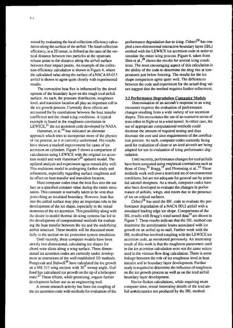
mined by evaluating the local collection efficiency calcu-<br />
lation along the surface of the airfoil. The local collection<br />
efficiency, in a 2D sense, is defined as the ratio of the ver-<br />
tical distance between two particles at the upstream<br />
release point to the distance along the airfoil surface<br />
between their impact points. An example of the collec-<br />
tion efficiency calculation is shown in Figure 4, where<br />
the calculated value along the surface of a NACA 65-015<br />
airfoil is shown to agree quite closely with experimental<br />
results.<br />
The convective heat flux is influenced by the devcl-<br />
opment of the boundary layer on the rough iced airfoil<br />
surface. As such, the pressure distribution, roughness<br />
lcvcl, and transition location alI play an important roll in<br />
the iw growth process. Currently these effects are<br />
accounted for by correlations between the heat transfer<br />
coefficient and the cloud icing conditions. A typical<br />
example is found in the roughness correlation in<br />
LEWICE?’ the ice accretion code developed by NASA.<br />
Hansman, et al.I4 has indicated an alternate<br />
approach which tries to incorporate more of the physics<br />
of the process, as it is currently understood. His results<br />
have shown a marked improvement for cases of ice<br />
accretion on cylinders. Figure 5 shows a comparison of<br />
calculations using LEWICE with the original ice accre-<br />
tion model and with Hansman’sZ updated model. The<br />
updated analysis and experiment agree remarkably well.<br />
This mulkone model is undergoing further study and<br />
refinement, especially regarding surface roughness and<br />
its effect on heat transfer and transition location.<br />
Most computer codes treat the heat flux into the sur-<br />
face as a specified constant value during the entire. simu-<br />
lation. This constant is normally taken to be zero thus<br />
prescribing an insulated boundary. However, heat flux<br />
into the airfoil surface may play an important role in the<br />
development of the ice shape, especially in the initial<br />
moments of the ice accretion. This possibility along with<br />
the desire to model thermal de-icing systems has led to<br />
the development of computational methods for evaluat-<br />
ing the heat transfer between the ice and the underlying<br />
airfoil smcture. These models will be discussed more<br />
fully in the section on ice protection system simulation.<br />
Until recently, these computer models have been<br />
strictly two dimensional, calculating ice shapes for<br />
chord-wise slices along a wing surface. Three dimen-<br />
sional ice accretion codes are currently under devclop-<br />
mcnt as extensions of the well established 2D methods.<br />
Potapczuk and Bidwe1Ix have calculated the ice growth<br />
on a MS-317 wing section with 30’ sweep angle. Guf-<br />
fond has calculated ice growth on the tip of a helicopter<br />
r0tor.2~ These efforts, while promising, require. further<br />
development before use as an engineering tool.<br />
A recent research activity has been the coupling of<br />
the ice accretion code with methods for evaluation of the<br />
performance degradation due to icing. Cebeciz8 has cou-<br />
pled a twodimensional interactive boundary layer (IBL)<br />
method with the LEWICE ice accretion code in order to<br />
simulate the entire icing process. Figure 6, taken from<br />
Shin et a~.,” shows the results for several icing condi-<br />
tions. The most encouraging aspect of this calculation is<br />
the ability of the code to determine the drag rise at tem-<br />
peratures just below freezing. The results for the ice<br />
shape comparison agree quite well. The differences<br />
between the code and experiment for the actual drag val-<br />
ues suggest that the method requires further refinement<br />
3.2 Performance Deeradation ComDuter Model5<br />
Determination of an aircraft’s response to an icing<br />
encounter requires the evaluation of performance<br />
changes resulting from a wide variety of ice accretion<br />
shapes. This necessitates the use of an extensive series of<br />
tests either in flight or in a wind tunnel. In either casc, the<br />
use of appropriate computational methods could<br />
decrease the amount of required testing and thus<br />
decrease the cost and time requirements of the certification<br />
process. As such, computer codes currently being<br />
used for evaluation of clean or un-iced aircraft are being<br />
adapted for use in evaluation of icing performance degradation.<br />
Until recently, performance changes for iced akfoils<br />
have been com uted usin empirical correlations such as<br />
those of Gray,% Bragg:‘and Flemming et al.?’ These<br />
methods work well over a restricted set of environmental<br />
conditions, hut are not adequate for general use by potential<br />
aircraft designers. As a result, computer codes have<br />
also been developed to evaluate the changes in performance<br />
of airfoils, wings, and rotors due to the prescnce<br />
of ice on critical surfaces.<br />
CebeciZ8 has used the IBL code to evaluate he performance<br />
degradation of a NACA 0012 airfoil with a<br />
simulated leading edge ice shape. Comparisons of the<br />
IBLresults with Bragg’s wind tunnel data33 are shown in<br />
Figure 7. These results indicate that the IBL method can<br />
determine the aerodynamic losses associated with ice<br />
growth on an airfoil up to stall. Further work with the<br />
IBL method has involved coupling with the LEWICE ice<br />
accretion code, as mentioned previously. An interesting<br />
result of this work is that the roughness parameters used<br />
in the ice accretion calculation were not the same values<br />
used in the viscous-flow drag calculation. There is some<br />
linkage between the role of ice roughness level in heat<br />
Bansfer and in boundary layer development. Further<br />
study is required to determine the influence of roughness<br />
on the ice growth process as well as on the iced airfoil<br />
boundary layer development.<br />
Navier-Stokes calculations, while requiring more<br />
computer time, reveal interesting details of the iced airfoil<br />
aemiynamics not produced by the IBL method.


