CVS 1000R Electro-Pneumatic Rotary Positioner - CVS Controls
CVS 1000R Electro-Pneumatic Rotary Positioner - CVS Controls
CVS 1000R Electro-Pneumatic Rotary Positioner - CVS Controls

Create successful ePaper yourself
Turn your PDF publications into a flip-book with our unique Google optimized e-Paper software.
9<br />
<strong>CVS</strong> <strong>Controls</strong> Ltd.<br />
Product Manual: <strong>Electro</strong>-<strong>Pneumatic</strong> <strong>Positioner</strong> YT-<strong>1000R</strong><br />
<strong>CVS</strong> <strong>Controls</strong> Ltd.<br />
Process Management<br />
Lock Screw<br />
Adjustment - A/M Switch (Auto/Manual)<br />
1. A/M switch adjusts the valve operation to automatic or<br />
manual.<br />
2. When produced, YT-1000L is set at “A(Automatic)”. If<br />
user prefers the positioned setting as “M(Manual)”, the<br />
setting can be changed by turning the switch<br />
counter-clockwise. (Figure 20)<br />
Lock Screw<br />
Auto Manual Switch<br />
3. If it is set as “M(Manual)”, the air pressure will be<br />
supplied to the actuator directly. Always set back to<br />
“A(Automatic)” after setting change.<br />
4. If OUT2 in a single acting actuator or double acting<br />
actuator is used, A/M switch will not operate.<br />
Adjustment - Seat Adjuster<br />
Seat Adjuster<br />
1. Seat adjustment is set according to the customers<br />
request before the positioner is delivered. Please do not<br />
adjust the seat adjuster.<br />
2. Seat adjuster is always used for double acting<br />
actuators and adjusted when the pressure balance point<br />
must be changed. Please do not touch the seat adjuster,<br />
because it can affect the positioner’s performance.<br />
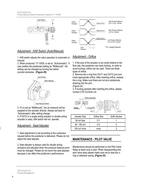
Output<br />
Pressure<br />
Output<br />
Pressure<br />
Output<br />
Pressure<br />
Input<br />
Pressure<br />
Adjustment - Orifice<br />
1. If the size of the actuator is too small relative to the<br />
flow rate, the positioner can have hunting. In order to<br />
avoid hunting, orifice can be used. There are three<br />
types of orifice.<br />
2. Remove the o-ring from OUT1 and OUT2 port and<br />
insert appropriate orifice. After inserting orifice, replace<br />
the o-ring. Make sure there are not any substances<br />
entering into the port.<br />
(Figure 22)<br />
3. If hunting persists after inserting the orifice, please<br />
contact <strong>CVS</strong> <strong>Controls</strong> Ltd.<br />
Orifice Diameter<br />
Orifice O-ring (P5)<br />
Balanced Point<br />
Balanced Point<br />
Balanced Point<br />
OUT 2 OUT1<br />
Actuator Size Orifice Size Suffix Symbol<br />
90 cm 3 less O 1 1<br />
90 - 180 cm 3 O 2 2<br />
180 cm 3 more none 3<br />
MAINTENANCE - PILOT VALVE<br />
High Pressure Balance<br />
(0.9~1.0 Ps) - Normal<br />
Med. Pressure Balance<br />
(0.5 Ps) - Normal<br />
Low Pressure Balance<br />
(0.4~0.5 Ps) - Normal<br />
* Ps - Supply Pressure<br />
Maintenance should be performed on the Pilot Valve<br />
Relay at least once a year. When disassembling the<br />
pilot valve relay please make sure not to lose the oring<br />
or stabilizer spring. (Figure 23)