
Create successful ePaper yourself
Turn your PDF publications into a flip-book with our unique Google optimized e-Paper software.
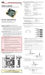
FEATURES<br />
• Ultra Compact, High Performance<br />
Microstepping Driver<br />
• Advanced 2nd Generation Current<br />
Control for Exceptional Performance<br />
and Smoothness<br />
• Single Supply: +12 to +48 VDC<br />
• Low Cost<br />
2.33"/59.1mm<br />
• Extremely Compact<br />
• High Output Current up to 2 Amps RMS,<br />
2.8 Amps Peak (Per Phase)<br />
• 20 Microstep Resolutions up to<br />
51,200 Steps Per Rev Including:<br />
Degrees, Metric, Arc Minutes<br />
• Optically Isolated Logic Inputs will<br />
Accept +5 to +24 VDC Signals,<br />
Sourcing or Sinking<br />
• Automatic Current Reduction<br />
1.66"/42.1mm<br />
• Confi gurable:<br />
- Motor Run/Hold Current<br />
- Motor Direction vs. Direction Input<br />
- Microstep Resolution<br />
- Clock Type: Step and Direction,<br />
Quadrature, Step Up and Step Down<br />
- Programmable Digital Filtering for<br />
Clock and Direction Inputs<br />
• Setup Parameters May Be Switched<br />
On-The-Fly<br />
• Power and Signal Interface Options:<br />
- Pluggable Locking Wire Crimp<br />
- Pluggable Terminal Strip<br />
- 12.0” (30.5cm) Flying Leads<br />
• Graphical User Interface (GUI) for<br />
Quick and Easy Parameter Setup<br />
DESCRIPTION<br />
TM<br />
FORCE<br />
MICRO DRIVE<br />
MICROSTEPPING<br />
The ultra compact Microstepping MForce<br />
MicroDrive is a high performance, low<br />
cost microstepping driver that delivers<br />
unsurpassed smoothness and performance<br />
achieved through IMS’s advanced<br />
2nd generation current control. By applying<br />
innovative techniques to control<br />
current fl ow through the motor, resonance<br />
is signifi cantly dampened over the<br />
entire speed range and audible noise is<br />
reduced.<br />
Microstepping MForce MicroDrives accept<br />
a broad input voltage range from<br />
+12 to +48 VDC, delivering enhanced<br />
performance and speed. Oversized input<br />
capacitors are used to minimize power<br />
line surges, reducing problems that<br />
can occur with long runs and multiple<br />
drive systems. An extended operating<br />
range of –40° to +85°C provides long<br />
life, trouble free service in demanding<br />
environments.<br />
The high, per phase output current of<br />
up to 2 Amps RMS, 2.8 Amps Peak,<br />
allows the extremely compact MForce<br />
MicroDrive to control a broad array of<br />
motors from size 8 to size 34.<br />
The microstepping drive accepts up to 20<br />
resolution settings from full to 256 microsteps<br />
per full step, including: degrees,<br />
metric and arc minutes. These settings<br />
may be changed on-the-fl y or downloaded<br />
and stored in nonvolatile memory with the<br />
use of a simple GUI which is provided.<br />
TM<br />
Excellence in <strong>Motion</strong><br />
This eliminates the need for external<br />
switches or resistors. Parameters are<br />
changed via an SPI port.<br />
Power and signal in ter face con nec tions<br />
are ac com plished with either a pluggable<br />
locking wire crimp, terminal strip or 12.0"<br />
(30.5cm) fl ying leads. Motor phases are<br />
connected via a pluggable 4-pin locking<br />
wire crimp connector. Optional cables<br />
are avail able for ease of con nect ing and<br />
con fi g ur ing the MForce MicroDrive.<br />
The Microstepping MForce MicroDrive is a<br />
compact, powerful and inexpensive solution<br />
that will reduce system cost, design<br />
and assembly time for a large range of<br />
applications.<br />
CONFIGURING<br />
The IMS SPI Motor Interface software is<br />
an easy to in stall and use GUI for confi<br />
g ur ing Microstepping MForce from a<br />
computer's USB port. GUI access is via<br />
the IMS SPI Motor Interface included on<br />
the CD shipped with the product, or from<br />
www.imshome.com.<br />
The IMS SPI Motor Interface features:<br />
Easy installation.<br />
Automatic detection of MForce version<br />
and communication confi guration.<br />
Will not set out-of-range values.<br />
Tool-tips display valid range<br />
setting for each option.<br />
Simple screen interfaces.<br />
www.imshome.com
MForce MicroDrive – MICROSTEPPING<br />
STANDARD SPEC I FI CA TIONS<br />
INPUT VOLTAGE (+V) Range<br />
+12 to +48 VDC<br />
Power supply current requirements = 2A (maximum) per MForce MicroDrive.<br />
Actual power supply current will depend on voltage and load.<br />
OUTPUT CURRENT<br />
RMS (Max)<br />
Peak (Per Phase)<br />
2 Amps<br />
2.8 Amps<br />
ISOLATED INPUT<br />
Step Clock, Direction and Enable<br />
Voltage Range +5 to +24 VDC Sourcing or Sinking<br />
Digital Filter Range 50 nS to 12.9 µS (10 MHz to 38.8 kHz)<br />
Clock Types Step/Direction, Quadrature, Step Up/Step Down<br />
Step Frequency 2 MHz Default (5 MHz Max)<br />
MOTION<br />
Number of Settings 20<br />
200, 400, 800, 1000, 1600, 2000, 3200, 5000,<br />
Resolution<br />
Steps Per Revolution<br />
6400, 10000, 12800, 20000, 25000, 25600,<br />
40000, 50000, 51200, 36000 (0.01 deg/µstep),<br />
21600 (1 arc minute/µstep), 25400 (0.001mm/µstep)<br />
THERMAL Heat Sink Temperature –40° to +85°C<br />
SETUP PARAMETERS<br />
2 MForce MicroDrive – Microstepping REV050707<br />
Function Range Units Default<br />
MHC Motor Hold Current 0 to 67 (67 = max 2.0 Amps RMS Output Current) percent 5% of 100 (100 = 3.0 Amps)<br />
MRC Motor Run Current 1 to 67 (67 = max 2.0 Amps RMS Output Current) percent 25% of 100 (100 = 3.0 Amps)<br />
MSEL Microstep Resolution<br />
1, 2, 4, 5, 8, 10, 16, 25, 32, 50,<br />
64, 100, 108, 125, 127, 128, 180,<br />
200, 250, 256<br />
µsteps per full<br />
step<br />
256<br />
DIR Motor Direction Override 0/1 — CW<br />
HCDT Hold Current Delay Time 0 or 2–65535 mSec 500<br />
CLK TYPE Clock Type Step/Dir, Quadrature, Up/Down — Step/Dir<br />
CLK IOF Clock and Direction Filter<br />
50 nS to 12.9 µS<br />
(10 MHz to 38.8 kHz)<br />
nS ( MHz) 200 nS (2.5 MHz)<br />
USER ID User ID Customizable 1–3 characters IMS<br />
EN ACT Enable Active High/Low — High<br />
All parameters are set using the supplied IMS SPI Motor Interface GUI and may be changed on-the-fl y.<br />
An optional Parameter Setup Cable is recommended with fi rst orders.<br />
MOTOR RECOMMENDATIONS<br />
IMS PART NUMBERS Size 14 (0.75 Amps) Size 17 (1.5 Amps) Size 23 (2.4 Amps)<br />
SINGLE LENGTH M-1410-0.75 M-1713-1.5 M-2218-2.4<br />
DOUBLE LENGTH – M-1715-1.5 M-2222-2.4<br />
TRIPLE LENGTH – M-1719-1.5 M-2231-2.4<br />
MOTOR PERFORMANCE<br />
Speed-Torque<br />
Single Length 17 Motor (IMS p/n M-1713-1.5) Double Length 17 Motor (IMS p/n M-1715-1.5) Triple Length 17 Motor (IMS p/n M-1719-1.5)<br />
60<br />
42<br />
60<br />
42<br />
60<br />
42<br />
50<br />
35<br />
50<br />
35<br />
50<br />
35<br />
40<br />
28<br />
40<br />
28<br />
40<br />
28<br />
30<br />
21<br />
30<br />
21<br />
30<br />
21<br />
20<br />
14<br />
20<br />
14<br />
20<br />
14<br />
10<br />
24 VDC<br />
48 VDC<br />
7<br />
10<br />
24 VDC<br />
48 VDC<br />
7<br />
10<br />
24 VDC<br />
48 VDC<br />
7<br />
0<br />
0<br />
0<br />
0 1000 2000 3000 4000 5000 6000 7000<br />
0 1000 2000 3000 4000 5000 6000 7000<br />
0 1000 2000 3000 4000 5000 6000 7000<br />
(300) (600) (900) (1200) (1500) (1800) (2100)<br />
(300) (600) (900) (1200) (1500) (1800) (2100)<br />
(300) (600) (900) (1200) (1500) (1800) (2100)<br />
Torque in Oz-In<br />
Speed in Full Steps per Second (RPM)<br />
Torque in N-cm<br />
Torque in Oz-In<br />
Speed in Full Steps per Second (RPM)<br />
Torque in N-cm<br />
Torque in Oz-In<br />
Speed in Full Steps per Second (RPM)<br />
Single Length 23 Motor (IMS p/n M-2218-2.4) Double Length 23 Motor (IMS p/n M-2222-2.4) Triple Length 23 Motor (IMS p/n M-2231-2.4)<br />
Torque in Oz - In<br />
225<br />
200<br />
175<br />
150<br />
125<br />
100<br />
75<br />
50<br />
25<br />
0<br />
0<br />
1000<br />
(300)<br />
2000<br />
(600)<br />
3000<br />
(900)<br />
4000<br />
(1200)<br />
5000<br />
(1500)<br />
24 VDC<br />
45 VDC<br />
Speed in Full Steps per Second (RPM)<br />
6000<br />
(1800)<br />
159<br />
141<br />
124<br />
106<br />
88<br />
71<br />
53<br />
35<br />
18<br />
7000<br />
(2100)<br />
Torque in N - cm<br />
Torque in Oz - In<br />
225<br />
200<br />
175<br />
150<br />
125<br />
100<br />
75<br />
50<br />
25<br />
0<br />
0<br />
1000<br />
(300)<br />
2000<br />
(600)<br />
3000<br />
(900)<br />
4000<br />
(1200)<br />
5000<br />
(1500)<br />
24 VDC<br />
45 VDC<br />
6000<br />
(1800)<br />
Speed in Full Steps per Second (RPM)<br />
159<br />
141<br />
124<br />
106<br />
88<br />
71<br />
53<br />
35<br />
18<br />
7000<br />
(2100)<br />
Torque in N - cm<br />
Torque in N-cm
PIN/WIRE ASSIGNMENTS<br />
Pluggable<br />
Terminal Strip<br />
P1: I/O & POWER CONNECTOR<br />
Flying Leads<br />
Wire Colors<br />
Pluggable Locking<br />
Wire Crimp**<br />
Function<br />
Pin 1 White Pin 3 Optocoupler Reference<br />
Pin 2 — — No Connect<br />
Pin 3 Orange Pin 4 Step Clock Input<br />
Pin 4 Blue Pin 6 CW/CCW Direction Input<br />
Pin 5 Brown Pin 5 Enable Input<br />
Pin 6 Black Pin 1 Power Ground<br />
Pin 7 Red Pin 2 +V (+12 to +48 VDC)<br />
Pin 7 +5 VDC Output<br />
Pin 8 SPI Clock<br />
Pin 9 Communications Ground<br />
Pin 10 SPI Master In – Slave Out<br />
Pin 11 SPI Chip Select<br />
Pin 12 SPI Master Out – Slave In<br />
P2: COMM CONNECTOR (SPI)**<br />
10-Pin IDC Function<br />
Pin 1 No Connect<br />
Pin 2 No Connect<br />
Pin 3 No Connect<br />
Pin 4 SPI Chip Select<br />
Pin 5 Communications Ground<br />
Pin 6 +5 VDC Output<br />
Pin 7 SPI Master Out – Slave In<br />
Pin 8 SPI Clock<br />
Pin 9 No Connect<br />
Pin 10 SPI Master In – Slave Out<br />
OPTIONS<br />
P3: MOTOR CONNECTOR<br />
Pluggable<br />
Locking Wire<br />
Crimp<br />
Function<br />
Pin 1 Phase /A<br />
Pin 2 Phase A<br />
Pin 3 Phase /B<br />
Pin 4 Phase B<br />
Motors and Encoders<br />
IMS offers a wide range of motors, encoders and accessories<br />
recommended for interface with the Microstepping MForce<br />
MicroDrive. For complete specifi cations on these products,<br />
please visit the IMS web site at www.imshome.com.<br />
Power Supplies<br />
IMS recommends the following power supplies for operating<br />
the MForce MicroDrive: IP402, IP404, ISP200-4. Complete<br />
power supply specifi cations at www.imshome.com.<br />
ACCESSORIES<br />
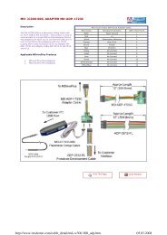
Parameter Setup Cable and Adapter<br />
The optional 12.0' (3.6m) parameter setup cable MD-CC300-<br />
000 facilitates communications interface from the Microstepping<br />
MForce MicroDrive to a PC's USB port with pluggable<br />
mating connectors. MForce with 12-pin pluggable locking<br />
wire crimp connector also require adapter MD-ADP-1723C.<br />
Recommended with fi rst order.<br />
Prototype Development Cables<br />
To speed prototyping, development cables are available with<br />
locking pluggable wire crimp mates to:<br />
I/O & Power: 12-pin Connector (2 lengths)<br />
12.0" (30.5cm) ........................... ADP-3512-FL<br />
10.0' (3.0m)................................ PD12-1434-FL3<br />
Motor Interface: 4-pin Connector<br />
10.0' (3.0m)................................ PD04-MF17-FL3<br />
Accessories details at: www.imshome.com/cables_cordsets.html<br />
**The 12-Pin Pluggable Locking<br />
Wire Crimp connector at P1<br />
eliminates the P2 connector.<br />
MECHANICAL SPECIFICATIONS<br />
Dimensions in Inches (mm)<br />
2.140<br />
(54.36)<br />
1.655<br />
(42.05)<br />
1.300<br />
(33.02)<br />
P1 Connector Options<br />
P1<br />
P2<br />
12.0<br />
(304.8)<br />
P2<br />
P1<br />
0.44<br />
(11.2)<br />
Flying Leads 7-Pin Pluggable Clamp 12-Pin Pluggable<br />
Type Terminal Strip Locking Wire Crimp**<br />
P2 Connector Options<br />
10-Pin IDC<br />
2.325<br />
(59.06)<br />
ORDER INFORMATION<br />
P2<br />
2X Ø 0.150<br />
(2X Ø 3.81)<br />
I/O & Power I/O & Power I/O, Power & Comm<br />
Comm<br />
No Connector**<br />
MForce MicroDrive – Microstepping REV050707 3<br />
P1<br />
MFM1 S 17N4<br />
P1: I/O & Power<br />
F = 12" Flying Leads<br />
P = Pluggable Clamp<br />
Type Terminal Strip<br />
C = 12-Pin Locking Wire<br />
Crimp (Includes I/O,<br />
Power and Comm)<br />
P1<br />
P3<br />
0.36<br />
(9.1)<br />
Example: Part Number MFM1PSD17N4 is a<br />
Microstepping MForce MicroDrive with<br />
pluggable I/O & power interface, SPI communications<br />
with 10-pin IDC connector and 4-pin motor interface.<br />
1.765<br />
(44.83)<br />
0.201<br />
(5.11)<br />
P3: Motor Interface<br />
4-Pin Locking Wire Crimp<br />
P2: Communications<br />
D = SPI with 10-Pin IDC Connector<br />
Z = None. Used with 12-Pin<br />
Locking Wire Crimp in P1
2.33"/59.1mm<br />
STANDARD FEATURES<br />
• Highly Integrated, High Performance<br />
Microstepping Driver and <strong>Motion</strong> Controller<br />
• Advanced 2nd Generation Current<br />
Control for Exceptional Performance<br />
and Smoothness<br />
• Single Supply: +12 to +48 VDC<br />
• Low Cost<br />
• Extremely Compact<br />
• High Output Current up to 2 Amps RMS,<br />
2.8 Amps Peak (Per Phase)<br />
• Auxiliary Logic Power Supply Input<br />
• 20 Microstep Resolutions up to<br />
51,200 Steps Per Rev Including:<br />
Degrees, Metric, Arc Minutes<br />
• Open or Optional Closed Loop Control<br />
• Programmable Motor Run and Hold Currents<br />
• Four +5 to +24 VDC I/O Lines<br />
Accept Sourcing or Sinking Outputs<br />
• One 10 Bit Analog Input Selectable: 0 to<br />
+10 VDC, 0 to +5 VDC, 0-20 mA, 4-20 mA<br />
• 0 to 5MHz Step Clock Rate<br />
Selectable in 0.59Hz In cre ments<br />
• RS-422/485 or Optional CANopen*<br />
Communications<br />
• 62 Software Addresses for<br />
Multi-Drop Communications<br />
• Simple 1 to 2 Character Instructions<br />
• Power and Signal Interface Options:<br />
- Pluggable Terminal Strip<br />
- 12.0” (30.5cm) Flying Leads<br />
EXPANDED PLUS 2 FEATURES<br />
• +5 to +24 VDC Tolerant I/O Lines<br />
Sourcing or Sinking, Inputs and Outputs:<br />
- 8 I/O Lines with Electronic Gearing (or)<br />
- 4 I/O Lines with External/Remote<br />
Encoder for Closed Loop Control<br />
• High Speed Position Capture Input or<br />
Trip Output<br />
• Pluggable Locking Wire Crimp Interface<br />
*CANopen may not support some objects.<br />
1.66"/42.1mm<br />
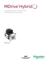
DESCRIPTION<br />
TM<br />
FORCE<br />
MICRO DRIVE<br />
The ultra compact <strong>Motion</strong> Control<br />
MForce MicroDrive offers system designers<br />
a low cost, high performance<br />
microstepping driver integrated with<br />
an in tel li gent, programmable motion<br />
con trol ler.<br />
The unsurpassed smoothness and<br />
performance delivered by MForce MicroDrives<br />
are achieved through IMS's<br />
advanced 2nd generation current control.<br />
By applying innovative techniques<br />
to control current fl ow through the<br />
motor, resonance is signifi cantly dampened<br />
over the entire speed range and<br />
audible noise is reduced.<br />
<strong>Motion</strong> Control MForce MicroDrives<br />
accept a broad input voltage range<br />
from +12 to +48 VDC, delivering<br />
enhanced performance and speed.<br />
Oversized input capacitors are used<br />
to minimize power line surges, reducing<br />
problems that can occur with long<br />
runs and multiple drive systems. An<br />
extended operating range of –40° to<br />
+85°C provides long life, trouble free<br />
service in demanding environments.<br />
A high, per phase output current of<br />
up to 2 Amps RMS, 2.8 Amps Peak,<br />
allows the extremely compact MForce<br />
MicroDrive to control a broad array of<br />
motors from size 8 to size 34.<br />
Stan dard features include four +5 to<br />
+24 volt general pur pose I/O lines, one<br />
10 bit analog in put, 0 to 5MHz step<br />
clock rate, 20 microstep res o lu tions<br />
up to 51,200 steps per rev o lu tion,<br />
and full fea tured easy-to-program instruc<br />
tion set.<br />
Expanded features in the Plus 2 version<br />
include up to eight +5 to +24 volt general<br />
pur pose I/O lines and the capability of<br />
electronic gearing by following a rotary or<br />
linear axis at an electronically controlled<br />
ratio, or an output clock can be generated<br />
fi xed to the internal step clock.<br />
MOTION CONTROL<br />
[with optional CANopen]<br />
TM<br />
Excellence in <strong>Motion</strong><br />
<strong>Motion</strong> Control MForce MicroDrive<br />
Plus 2 are available with optional closed<br />
loop con trol. This increases functionality<br />
by adding stall detection, position<br />
main te nance and find index mark.<br />
The closed loop confi guration offers<br />
an expanded choice of line counts<br />
and resolutions by interfacing to a remotely<br />
mounted user-supplied external<br />
encoder.<br />
<strong>Motion</strong> Control MForce MicroDrives<br />
com mu ni cate over RS-422/485 which<br />
al lows for point-to-point or multiple unit<br />
con fi g u ra tions utilizing one com mu ni ca<br />
tion port. Addressing and hard ware<br />
support up to 62 uniquely addressed<br />
units com mu ni cat ing over a single line.<br />
Baud rate is selectable from 4.8 to<br />
115.2kbps.<br />
Optional communication protocols<br />
include CANopen. The CAN bus is<br />
2.0B active (11 and/or 29 bit) and<br />
is capable of all standard frequencies<br />
from 10kHz to 1MHz. CANopen features<br />
include node guarding, heartbeat<br />
producer, SDOs and PDOs. Highlights<br />
include variable PDO mapping and extended<br />
node identifi er.*<br />
Power and signal in ter face con nec tions<br />
are ac com plished using 12.0” (30.5cm)<br />
fl ying leads or a 7 position terminal<br />
strip. Plus 2 versions come with pluggable<br />
locking wire crimp connector.<br />
Motor phases are connected via a<br />
pluggable 4-pin locking wire crimp connector.<br />
Optional cables are available for<br />
ease of connecting and confi guring the<br />
MForce MicroDrive, and are recommended<br />
with fi rst order.<br />
The <strong>Motion</strong> Control MForce MicroDrive<br />
is a compact, powerful and inexpensive<br />
solution that will reduce system cost,<br />
design and assembly time for a large<br />
range of applications.<br />
www.imshome.com
MForce MicroDrive – MOTION CONTROL<br />
STANDARD SPEC I FI CA TIONS (Plus Versions)<br />
INPUT VOLTAGE (+V) Range<br />
+12 to +48 VDC<br />
Power supply current requirements = 2A (maximum) per MForce MicroDrive.<br />
Actual power supply current will depend on voltage and load.<br />
AUX. LOGIC INPUT VOLTAGE Range<br />
+12 to +24 VDC<br />
Maintains power to control and feedback circuits (only) when input voltage is removed.<br />
OUTPUT CURRENT<br />
RMS (Max)<br />
Peak (Per Phase)<br />
2 Amps<br />
2.8 Amps<br />
ANALOG INPUT<br />
Resolution<br />
Voltage Range<br />
10 Bit<br />
0 to +5 VDC, 0 to +10 VDC, 0-20 mA, 4-20 mA<br />
Number/Type 4 Sinking Outputs/4 Sourcing or Sinking Inputs<br />
GENERAL PURPOSE I/O<br />
Logic Range<br />
Output Sink Current<br />
Inputs and Outputs Tolerant to +24VDC, Inputs TTL Level Compatible<br />
Up to 600 mA per Channel<br />
Protection Over Temp, Short Circuit, Transient Over Voltage, Over Voltage, Inductive Clamp<br />
Type (Standard) RS-422/485<br />
Baud Rate 4.8 to 115.2kbps<br />
COMMUNICATION<br />
Type (Optional)<br />
ID<br />
CANopen DSP-402 (V2.0), DS-301 (V3.0), 2.0B Active<br />
11 and/or 29 Bit<br />
Isolation Galvanic<br />
Features Node Guarding, Heartbeat, SDOs, PDOs (Variable Mapping)<br />
Number of Settings 20<br />
MOTION<br />
SOFTWARE<br />
Open Loop<br />
Confi guration<br />
Counters<br />
Velocity<br />
Accel/Decel<br />
Number/Type 8 Sourcing or Sinking Outputs/Inputs (or 4 when Remote Encoder Option is Selected)<br />
GENERAL PURPOSE I/O Logic Range<br />
Sourcing Outputs +12 to +24 VDC, Inputs and Sinking Outputs Tolerant to +24 VDC,<br />
Inputs TTL Level Compatible<br />
Output Sink/Source Current Up to 600 mA per Channel<br />
Electronic Gearing<br />
Range<br />
MOTION<br />
‡ /Resolution/Threshold<br />
(External Clock In)<br />
Input Filter Range<br />
0.001 to 2.000/32 Bit/TTL<br />
50 nS to 12.9 µS (10 MHz to 38.8 kHz)<br />
Range ‡ (Secondary Clock Out) 1 to 1<br />
High Speed I/O<br />
Position Capture<br />
Input Filter Range<br />
Resolution<br />
50 nS to 12.9 µS (10 MHz to 38.8 kHz)<br />
32 Bit<br />
Trip Output – Speed/Resolution/Threshold 150 nS/32 Bit/TTL<br />
Closed Loop<br />
Confi guration<br />
(Optional)<br />
Remote<br />
Encoder<br />
Type<br />
Steps Per Revolution<br />
Resolution<br />
User-Supplied Differential Encoder<br />
See "Standard Specs Open Loop Steps/Rev" Above<br />
User-Defi ned<br />
Note: µstep/rev 2X the encoder count/rev minimum<br />
‡ Adjusting the microstep resolution can increase the range.<br />
2 MForce MicroDrive – <strong>Motion</strong> Control REV050707<br />
Steps Per Revolution<br />
200, 400, 800, 1000, 1600, 2000, 3200, 5000,<br />
6400, 10000, 12800, 20000, 25000, 25600,<br />
40000, 50000, 51200, 36000 (0.01 deg/µstep),<br />
21600 (1 arc minute/µstep), 25400 (0.001mm/µstep)<br />
Type Position, En cod er/32 Bit<br />
Edge Rate (Max) 5 MHz<br />
Range +/- 5,000,000 Steps Per Second<br />
Resolution 0.5961 Steps Per Second<br />
Range 1.5 x 10⁹ Steps Per Second2 Resolution 90.9 Steps Per Second2 Program Storage Type/Size Flash/6384 Bytes<br />
User Registers (4) 32 Bit<br />
User Program Labels and Variables 192<br />
Math Functions +, –, ×, ÷, >,
MOTOR PERFORMANCE<br />
Speed-Torque<br />
Single Length 17 Motor (IMS p/n M-1713-1.5) Double Length 17 Motor (IMS p/n M-1715-1.5) Triple Length 17 Motor (IMS p/n M-1719-1.5)<br />
60<br />
42<br />
60<br />
42<br />
60<br />
42<br />
50<br />
35<br />
50<br />
35<br />
50<br />
35<br />
40<br />
28<br />
40<br />
28<br />
40<br />
28<br />
30<br />
21<br />
30<br />
21<br />
30<br />
21<br />
20<br />
14<br />
20<br />
14<br />
20<br />
14<br />
10<br />
24 VDC<br />
48 VDC<br />
7<br />
10<br />
24 VDC<br />
48 VDC<br />
7<br />
10<br />
24 VDC<br />
48 VDC<br />
7<br />
0<br />
0<br />
0<br />
0 1000 2000 3000 4000 5000 6000 7000<br />
0 1000 2000 3000 4000 5000 6000 7000<br />
0 1000 2000 3000 4000 5000 6000 7000<br />
(300) (600) (900) (1200) (1500) (1800) (2100)<br />
(300) (600) (900) (1200) (1500) (1800) (2100)<br />
(300) (600) (900) (1200) (1500) (1800) (2100)<br />
Torque in Oz-In<br />
PIN/WIRE ASSIGNMENTS<br />
Pluggable<br />
Terminal Strip<br />
Wire<br />
Crimp<br />
P1: I/O & POWER CONNECTOR<br />
PLUS – Standard Features<br />
Flying Leads<br />
Wire Colors<br />
PLUS 2 – Expanded Features<br />
Expanded I/O<br />
Function<br />
Function<br />
Pin 1 White/Yellow I/O 1<br />
Pin 2 White/Orange I/O 2<br />
Pin 3 White/Violet I/O 3<br />
Pin 4 White/Blue I/O 4<br />
Pin 5 Green Analog Input<br />
Pin 6 Black Power/Aux Ground<br />
Pin 7 Red +V (+12 to +48 VDC)<br />
Optional<br />
Remote Encoder<br />
Closed Loop Control<br />
Pin 1 I/O Power I/O Power<br />
Pin 2 I/O Ground I/O Ground<br />
Pin 3 I/O 1 I/O 1<br />
Pin 4 I/O 2 I/O 2<br />
Pin 5 I/O 3 I/O 3<br />
Pin 6 I/O 4 I/O 4<br />
Pin 7 I/O 9 Channel A +<br />
Pin 8 I/O 10 Channel A –<br />
Pin 9 I/O 11 Channel B +<br />
Pin 10 I/O 12 Channel B –<br />
Pin 11 Capture/Trip I/O Capture/Trip I/O<br />
Pin 12 Analog In Analog In<br />
Pin 13 Step/Clock I/O Index +<br />
Pin 14 Direction/Clock I/O Index –<br />
Pin 15 +V (+12 to +48 VDC) +V (+12 to +48 VDC)<br />
Pin 16 Power/Aux Ground Power/Aux Ground<br />
Torque in N-cm<br />
Torque in Oz-In<br />
Speed in Full Steps per Second (RPM)<br />
Speed in Full Steps per Second (RPM)<br />
Speed in Full Steps per Second (RPM)<br />
Single Length 23 Motor (IMS p/n M-2218-2.4) Double Length 23 Motor (IMS p/n M-2222-2.4) Triple Length 23 Motor (IMS p/n M-2231-2.4)<br />
Torque in Oz - In<br />
225<br />
200<br />
175<br />
150<br />
125<br />
100<br />
75<br />
50<br />
25<br />
0<br />
0<br />
1000<br />
(300)<br />
2000<br />
(600)<br />
3000<br />
(900)<br />
4000<br />
(1200)<br />
5000<br />
(1500)<br />
24 VDC<br />
45 VDC<br />
Speed in Full Steps per Second (RPM)<br />
6000<br />
(1800)<br />
159<br />
141<br />
124<br />
106<br />
88<br />
71<br />
53<br />
35<br />
18<br />
7000<br />
(2100)<br />
Torque in N - cm<br />
Torque in Oz - In<br />
225<br />
200<br />
175<br />
150<br />
125<br />
100<br />
75<br />
50<br />
25<br />
0<br />
0<br />
1000<br />
(300)<br />
2000<br />
(600)<br />
3000<br />
(900)<br />
P2: COMM CONNECTOR<br />
RS-422/485<br />
10-Pin<br />
IDC<br />
Wire<br />
Crimp<br />
Function<br />
Pin 1 Pin 9 TX +<br />
Pin 2 Pin 10 TX –<br />
Pin 3 Pin 7 RX +<br />
Pin 4 Pin 8 RX –<br />
Pin 5 Pin 5<br />
Aux-Logic (+12<br />
to +24 VDC)<br />
Pin 6 Pin 6 RX +<br />
Pin 7 Pin 3 RX –<br />
Pin 8 Pin 4 TX –<br />
Pin 9 Pin 1 TX +<br />
Pin 10 Pin 2 Comm Ground<br />
DB9<br />
CANopen<br />
Function<br />
Pin 1 No Connect<br />
Pin 2 CAN Low<br />
Pin 3 CAN –V<br />
Pin 4 Aux Power<br />
Pin 5 Shield<br />
Pin 6 CAN –V<br />
Pin 7 CAN High<br />
Pin 8 No Connect<br />
Pin 9 CAN +V<br />
P3: MOTOR CONNECTOR<br />
Pluggable<br />
Locking<br />
Wire Crimp<br />
Function<br />
Pin 1 Phase /A<br />
Pin 2 Phase A<br />
Pin 3 Phase /B<br />
Pin 4 Phase B<br />
4000<br />
(1200)<br />
5000<br />
(1500)<br />
P1<br />
Torque in N-cm<br />
Torque in Oz-In<br />
MECHANICAL SPECIFICATIONS<br />
Dimensions in Inches (mm)<br />
2.140<br />
(54.36)<br />
24 VDC<br />
45 VDC<br />
Speed in Full Steps per Second (RPM)<br />
6000<br />
(1800)<br />
1.655<br />
(42.05)<br />
1.300<br />
(33.02)<br />
159<br />
141<br />
124<br />
106<br />
88<br />
71<br />
53<br />
35<br />
18<br />
7000<br />
(2100)<br />
Torque in N - cm<br />
P2<br />
Torque in Oz - In<br />
225<br />
200<br />
175<br />
150<br />
125<br />
100<br />
P1 Connector Options<br />
12.0<br />
(304.8)<br />
75<br />
50<br />
25<br />
0<br />
0<br />
2.325<br />
(59.06)<br />
P2<br />
1000<br />
(300)<br />
P1<br />
2000<br />
(600)<br />
0.44<br />
(11.2)<br />
3000<br />
(900)<br />
Flying Leads 7-Pin Pluggable Clamp 16-Pin Pluggable<br />
Type Terminal Strip Locking Wire Crimp<br />
(Plus2 Version Only)<br />
P2 Connector Options<br />
Comm Comm Comm<br />
10-Pin IDC 10-Pin Friction Lock<br />
DB9<br />
Wire Crimp<br />
(CANopen Only)<br />
P2<br />
4000<br />
(1200)<br />
2X Ø 0.150<br />
(2X Ø 3.81)<br />
MForce MicroDrive – <strong>Motion</strong> Control REV050707 3<br />
P1<br />
5000<br />
(1500)<br />
0.14<br />
(3.6)<br />
24 VDC<br />
45 VDC<br />
Speed in Full Steps per Second (RPM)<br />
6000<br />
(1800)<br />
P3<br />
P1<br />
1.765<br />
(44.83)<br />
I/O & Power I/O & Power Expanded I/O & Power<br />
0.20<br />
(5.0)<br />
P2<br />
159<br />
141<br />
124<br />
106<br />
88<br />
71<br />
53<br />
35<br />
18<br />
7000<br />
(2100)<br />
Torque in N - cm<br />
0.201<br />
(5.11)<br />
Torque in N-cm
MForce MicroDrive – MOTION CONTROL<br />
OPTIONS<br />
Remote Encoder (Plus 2 versions only)<br />
For optional closed loop control, <strong>Motion</strong> Control MForce<br />
MicroDrive Plus 2 versions are available with differential encoder<br />
inputs for use with a remote encoder (not supplied).<br />
Motors and Encoders<br />
IMS offers a wide range of motors, encoders and accessories<br />
recommended for interface with the <strong>Motion</strong> Control MForce<br />
MicroDrive. For complete specifi cations on these products,<br />
please visit the IMS web site at www.imshome.com.<br />
Power Supplies<br />
IMS recommends the following power supplies for operating<br />
the MForce MicroDrive: IP402, IP404, ISP200-4. For<br />
complete power supply specifi cations, visit the IMS web site<br />
at www.imshome.com.<br />
ORDER INFORMATION<br />
Plus<br />
P1: I/O & Power<br />
F = 12" Flying Leads<br />
P = Pluggable Clamp<br />
Type Terminal Strip<br />
P3: Motor Interface<br />
4-Pin Locking Wire Crimp<br />
P2: Communications<br />
RD = RS-422/485 with 10-Pin IDC Connector<br />
RL = RS-422/485 with 10-Pin Friction Lock Wire Crimp<br />
CB = CANopen with DB9 Connector<br />
Example: Part Number MFI1PRD17N4 is a <strong>Motion</strong> Control<br />
MForce MicroDrive Plus with pluggable I/O & power interface,<br />
RS-422/485 communications with 10-pin IDC connector and<br />
4-pin motor interface.<br />
ACCESSORIES<br />
Communications Converter Cable and Adapter<br />
With an in-line RS-422 converter, the optional 12.0' (3.6m)<br />
cable, and adapter required for 10-Pin Wire Crimp connector,<br />
facilitate the parameter setting of a single <strong>Motion</strong><br />
Control MForce MicroDrive from its P2 connector to a PC's<br />
USB port with pluggable mating connectors. Recommended<br />
with fi rst order.<br />
USB to 10-Pin IDC ............................ MD-CC400-000<br />
10-Pin IDC to Wire Crimp Adapter ...... MD-ADP-H<br />
Prototype Development Cables<br />
To speed prototyping, 10.0' (3.0m) development cables are<br />
available with pluggable wire crimp mating connectors to:<br />
I/O: 16-pin Connector ....................... PD16-1417-FL3<br />
Comm: 10-pin Connector ................... PD10-1434-FL3<br />
Motor Interface: 4-pin Connector ........ PD04-MF17-FL3<br />
Accessories details at: www.imshome.com/cables_cordsets.html<br />
MFI1 17N4 MFI3C 17N4 – EE<br />
Plus2 P1: I/O & Power<br />
16-Pin Locking<br />
Wire Crimp<br />
P3: Motor Interface<br />
4-Pin Locking Wire Crimp<br />
OPTION<br />
P2: Communications<br />
RD = RS-422/485 with 10-Pin IDC Connector<br />
RL = RS-422/485 with 10-Pin Friction Lock Wire Crimp<br />
CB = CANopen with DB9 Connector<br />
Example: Part Number MFI3CRD17N4 is a <strong>Motion</strong> Control<br />
MForce MicroDrive Plus2 with 16-pin I/O & power interface,<br />
RS-422/485 communications with 10-pin IDC connector and<br />
4-pin motor interface.<br />
Option: Include -EE to part number for optional interface to<br />
remote encoder (not supplied). Plus2 versions only.<br />
MForce MicroDrive – <strong>Motion</strong> Control REV050707 4
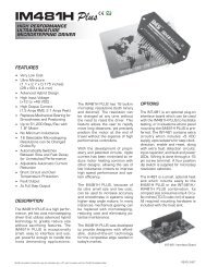
FEATURES<br />
• Highly Integrated, High Performance<br />
Microstepping Driver and Variable<br />
Speed Controller<br />
• Advanced 2nd Generation Current<br />
Control for Exceptional Performance<br />
and Smoothness<br />
• Single Supply: +12 to +48 VDC<br />
• Low Cost<br />
2.33"/59.1mm<br />
• Extremely Compact<br />
• High Output Current up to 2 Amps RMS,<br />
2.8 Amps Peak (Per Phase)<br />
• 20 Microstep Resolutions up to<br />
51,200 Steps Per Rev Including:<br />
Degrees, Metric, Arc Minutes<br />
• 10-bit Analog Speed Control Input<br />
Accepts:<br />
- 0 to +5 VDC<br />
- 0 to +10 VDC<br />
- 4 to 20 mA<br />
- 0 to 20 mA<br />
- 15 to 25 kHz PWM<br />
• Automatic Current Reduction<br />
• Electronically Confi gurable:<br />
- Motor Run/Hold Current<br />
- Microstep Resolution<br />
- Acceleration/Deceleration<br />
- Initial and Max Velocity<br />
- Hold Current Delay Time/Motor<br />
Settling Delay Time<br />
- Programmable Filtering for the<br />
Stop/Start Input<br />
1.66"/42.1mm<br />
• Setup Parameters May Be Switched<br />
On-The-Fly<br />
• Power and Signal Interface Options:<br />
- Pluggable Terminal Strip<br />
- 12.0” (30.5cm) Flying Leads<br />
• Graphical User Interface (GUI) for<br />
Quick and Easy Parameter Setup<br />
DESCRIPTION<br />
TM<br />
FORCE<br />
MICRO DRIVE<br />
The ultra compact Speed Control MForce<br />
MicroDrive offers system designers a low<br />
cost, high performance microstepping driver<br />
integrated with a variable speed controller.<br />
The unsurpassed smoothness and<br />
performance delivered by MForce MicroDrives<br />
are achieved through IMS's<br />
advanced 2nd generation current control.<br />
By applying innovative techniques to<br />
control current fl ow through the motor,<br />
resonance is signifi cantly dampened over<br />
the entire speed range and audible noise<br />
is reduced.<br />
Speed Control MForce MicroDrives accept<br />
a broad input voltage range from<br />
+12 to +48 VDC, delivering enhanced<br />
performance and speed. Oversized input<br />
capacitors are used to minimize power line<br />
surges, reducing problems that can occur<br />
with long runs and multiple drive systems.<br />
An extended operating range of –40° to<br />
+85°C provides long life, trouble free service<br />
in demanding environments.<br />
The high, per phase output current of<br />
up to 2 Amps RMS, 2.8 Amps Peak,<br />
allows the extremely compact MForce<br />
MicroDrive to control a broad array of<br />
motors from size 8 to size 34.<br />
Speed Control MForce MicroDrives feature<br />
a digital oscillator for accurate velocity<br />
control with an output frequency of up to 5<br />
Megahertz. Output frequency will vary with<br />
the signal applied to the speed control input<br />
and can be limited by the amount specifi ed<br />
by the Maximum Velocity parameter.<br />
Speed can be adjusted using three modes<br />
of operation: voltage, current and PWM.<br />
This allows control by a wide variety of<br />
sensors and devices.<br />
There are two basic methods of controlling<br />
the velocity: bidirectional and unidirec-<br />
SPEED CONTROL<br />
Excellence in <strong>Motion</strong><br />
tional. By moving the center point, both<br />
speed and direction are controlled by a<br />
potentiometer or joystick. By setting the<br />
center point to zero or the lower end of the<br />
potentiometer, only velocity is controlled<br />
by the speed control input; direction is<br />
controlled by a separate digital input.<br />
The Speed Control MForce MicroDrive<br />
has 18 setup parameters, which may be<br />
confi gured using the supplied IMS Analog<br />
Speed Control GUI, or a user-developed<br />
front-end communication over SPI. The<br />
setup parameters enable the user to<br />
confi gure operational parameters which<br />
are stored in nonvolatile memory.<br />
Power and signal in ter face con nec tions<br />
are ac com plished with either a pluggable<br />
terminal strip or 12.0" (30.5cm) fl ying<br />
leads. Motor phases are connected via a<br />
pluggable 4-pin locking wire crimp connector.<br />
Optional cables are avail able for ease<br />
of con nect ing and con fi g ur ing the Speed<br />
Control MForce MicroDrive: a compact,<br />
powerful and inexpensive solution that will<br />
reduce system cost, design and assembly<br />
time for a large range of applications.<br />
CONFIGURING<br />
The IMS Analog Speed Control is a software<br />
GUI for quick and easy parameter<br />
setup of the Speed Control MForce MicroDrive<br />
from a computer's USB port. GUI<br />
access is via the IMS SPI Motor Interface<br />
included onthe CD shipped with the product,<br />
or from www.imshome.com.<br />
IMS Analog Speed Control features:<br />
• Easy installation.<br />
• Automatic detection of MForce version<br />
and communication confi guration.<br />
• Will not set out-of-range values.<br />
• Tool-tips display valid range<br />
setting for each option.<br />
• Simple screen interfaces.<br />
TM<br />
www.imshome.com
MForce MicroDrive – SPEED CONTROL<br />
STANDARD SPEC I FI CA TIONS<br />
INPUT VOLTAGE (+V) Range<br />
+12 to +48 VDC<br />
Power supply current requirements = 2A (maximum) per MForce MicroDrive.<br />
Actual power supply current will depend on voltage and load.<br />
SPEED CONTROL<br />
Input<br />
A/D Resolution<br />
0 to +5 VDC*, 0 to +10 VDC, 4 to 20 mA, 0 to 20 mA or 15 to 25 kHz PWM<br />
10 bit<br />
OUTPUT CURRENT<br />
RMS (Max)<br />
Peak (Per Phase)<br />
2 Amps<br />
2.8 Amps<br />
Low Level 0 to +0.8 VDC<br />
LOGIC INPUT Start/Stop and Direction High Level +2.0 to +5.0 VDC<br />
Internal Pull-up Resistance (to +3.3 VDC) 20 kΩ<br />
Oscillator Frequency (Max) 5 MHz<br />
Number of Settings 20<br />
MOTION<br />
Microstep Resolution<br />
Steps Per Revolution<br />
200, 400, 800, 1000, 1600, 2000, 3200, 5000,<br />
6400, 10000, 12800, 20000, 25000, 25600,<br />
40000, 50000, 51200, 36000 (0.01 deg/µstep),<br />
21600 (1 arc minute/µstep), 25400 (0.001mm/µstep)<br />
THERMAL Heat Sink Temperature –40° to +85°C<br />
*10 k Ω potentiometer resistance.<br />
SETUP PARAMETERS<br />
A1 Analog Input Mode<br />
MOTOR RECOMMENDATIONS<br />
IMS PART NUMBERS Size 14 (0.75 Amps) Size 17 (1.5 Amps) Size 23 (2.4 Amps)<br />
SINGLE LENGTH M-1410-0.75 M-1713-1.5 M-2218-2.4<br />
DOUBLE LENGTH – M-1715-1.5 M-2222-2.4<br />
TRIPLE LENGTH – M-1719-1.5 M-2231-2.4<br />
2 MForce MicroDrive – Speed Control REV050707<br />
Function Range Units Default<br />
0 to +5 VDC, 0 to +10 VDC,<br />
4 to 20 mA, 0 to 20 mA, 15 to 25 kHz PWM<br />
— 0 to +5 VDC<br />
ACCL Acceleration 91 to 1.5 X 10 9 steps/second 2 1,000,000<br />
C Joystick Center 1 to 1022 counts 0<br />
DB Analog Deadband 0 to 255 counts 1<br />
DECL Deceleration 91 to 1.5 X 10 9 steps/second 2 1,000,000<br />
DIR Motor Direction Override Clockwise (CW) / Counterclockwise (CCW) — CW<br />
FAULT Fault/Checksum Error Error Code — None<br />
FS Analog Full Scale 1 to 1023 counts 1023<br />
HCDT Hold Current Delay Time HCDT + MSDT
MOTOR PERFORMANCE<br />
Speed-Torque<br />
Single Length 17 Motor (IMS p/n M-1713-1.5) Double Length 17 Motor (IMS p/n M-1715-1.5) Triple Length 17 Motor (IMS p/n M-1719-1.5)<br />
60<br />
42<br />
60<br />
42<br />
60<br />
42<br />
50<br />
35<br />
50<br />
35<br />
50<br />
35<br />
40<br />
28<br />
40<br />
28<br />
40<br />
28<br />
30<br />
21<br />
30<br />
21<br />
30<br />
21<br />
20<br />
14<br />
20<br />
14<br />
20<br />
14<br />
10<br />
24 VDC<br />
48 VDC<br />
7<br />
10<br />
24 VDC<br />
48 VDC<br />
7<br />
10<br />
24 VDC<br />
48 VDC<br />
7<br />
0<br />
0<br />
0<br />
0 1000 2000 3000 4000 5000 6000 7000<br />
0 1000 2000 3000 4000 5000 6000 7000<br />
0 1000 2000 3000 4000 5000 6000 7000<br />
(300) (600) (900) (1200) (1500) (1800) (2100)<br />
(300) (600) (900) (1200) (1500) (1800) (2100)<br />
(300) (600) (900) (1200) (1500) (1800) (2100)<br />
Torque in Oz-In<br />
PIN/WIRE ASSIGNMENTS<br />
Pluggable<br />
Terminal Strip<br />
Speed in Full Steps per Second (RPM)<br />
P1: I/O & POWER CONNECTOR<br />
Flying Leads<br />
Wire Colors<br />
P3: MOTOR CONNECTOR<br />
Function<br />
Pin 1 Violet Start/Stop Input<br />
Pin 2 Blue CW/CCW Direction Input<br />
Pin 3 Green Speed Control Input<br />
Pin 4 Yellow +5 VDC Output<br />
Pin 5 Gray Logic Ground<br />
Pin 6 Black Power Ground<br />
Pin 7 Red +V (+12 to +48 VDC)<br />
Pluggable Locking<br />
Wire Crimp<br />
Function<br />
Pin 1 Phase /A<br />
Pin 2 Phase A<br />
Pin 3 Phase /B<br />
Pin 4 Phase B<br />
Torque in N-cm<br />
Torque in Oz-In<br />
Speed in Full Steps per Second (RPM)<br />
Torque in N-cm<br />
MECHANICAL SPECIFICATIONS<br />
Dimensions in Inches (mm)<br />
2.140<br />
(54.36)<br />
1.655<br />
(42.05)<br />
1.300<br />
(33.02)<br />
P2<br />
Torque in Oz-In<br />
2.325<br />
(59.06)<br />
P1 Connector Options<br />
P1<br />
12.0<br />
(304.8)<br />
Flying Leads<br />
P2 Connector Options<br />
Speed in Full Steps per Second (RPM)<br />
Single Length 23 Motor (IMS p/n M-2218-2.4) Double Length 23 Motor (IMS p/n M-2222-2.4) Triple Length 23 Motor (IMS p/n M-2231-2.4)<br />
Torque in Oz - In<br />
225<br />
200<br />
175<br />
150<br />
125<br />
100<br />
75<br />
50<br />
25<br />
0<br />
0<br />
1000<br />
(300)<br />
2000<br />
(600)<br />
3000<br />
(900)<br />
4000<br />
(1200)<br />
5000<br />
(1500)<br />
24 VDC<br />
45 VDC<br />
Speed in Full Steps per Second (RPM)<br />
6000<br />
(1800)<br />
P2: COMM CONNECTOR<br />
10-Pin IDC Wire Crimp Function<br />
Pin 1 Pin 9 No Connect<br />
Pin 2 Pin 10 No Connect<br />
Pin 3 Pin 7 No Connect<br />
Pin 4 Pin 8 SPI Chip Select<br />
Pin 5 Pin 5 Communications Ground<br />
Pin 6 Pin 6 +5 VDC Output<br />
Pin 7 Pin 3 SPI Master Out – Slave In<br />
Pin 8 Pin 4 SPI Clock<br />
Pin 9 Pin 1 No Connect<br />
Pin 10 Pin 2 SPI Master In – Slave Out<br />
159<br />
141<br />
124<br />
106<br />
88<br />
71<br />
53<br />
35<br />
18<br />
7000<br />
(2100)<br />
Torque in N - cm<br />
Torque in Oz - In<br />
225<br />
200<br />
175<br />
150<br />
125<br />
100<br />
75<br />
50<br />
25<br />
0<br />
0<br />
1000<br />
(300)<br />
2000<br />
(600)<br />
3000<br />
(900)<br />
4000<br />
(1200)<br />
5000<br />
(1500)<br />
24 VDC<br />
45 VDC<br />
Speed in Full Steps per Second (RPM)<br />
6000<br />
(1800)<br />
159<br />
141<br />
124<br />
106<br />
88<br />
71<br />
53<br />
35<br />
18<br />
7000<br />
(2100)<br />
Torque in N - cm<br />
Torque in Oz - In<br />
225<br />
200<br />
175<br />
150<br />
125<br />
100<br />
75<br />
50<br />
25<br />
0<br />
0<br />
1000<br />
(300)<br />
P2<br />
2000<br />
(600)<br />
3000<br />
(900)<br />
P1<br />
4000<br />
(1200)<br />
2X Ø 0.150<br />
(2X Ø 3.81)<br />
0.44<br />
(11.2)<br />
7-Pin Pluggable Clamp<br />
Type Terminal Strip<br />
10-Pin IDC 10-Pin Friction Lock<br />
Wire Crimp<br />
MForce MicroDrive – Speed Control REV050707 3<br />
P1<br />
5000<br />
(1500)<br />
P2<br />
24 VDC<br />
45 VDC<br />
Speed in Full Steps per Second (RPM)<br />
I/O & Power I/O & Power<br />
Comm Comm<br />
P3<br />
6000<br />
(1800)<br />
159<br />
141<br />
124<br />
106<br />
88<br />
71<br />
53<br />
35<br />
18<br />
7000<br />
(2100)<br />
1.765<br />
(44.83)<br />
0.201<br />
(5.11)<br />
Torque in N - cm<br />
Torque in N-cm
OPTIONS<br />
Motors and Encoders<br />
IMS offers a wide range of motors, encoders and accessories<br />
recommended for interface with the Speed Control MForce<br />
MicroDrive. For complete specifi cations on these products,<br />
please visit the IMS web site at www.imshome.com.<br />
Power Supplies<br />
IMS recommends the following power supplies for operating<br />
the MForce MicroDrive: IP402, IP404, ISP200-4. Complete<br />
power supply specifi cations at www.imshome.com.<br />
ACCESSORIES<br />
Parameter Setup Cable and Adapter<br />
The optional 12.0' (3.6m) parameter setup cable part number<br />
MD-CC300-000 facilitates communications interface and is<br />
recommended with fi rst order. It connects the Speed Control<br />
MForce MicroDrive's P2 connector to a PC's USB port with<br />
pluggable mating connectors. MicroDrives with 10-pin friction<br />
lock wire crimp also require adapter MD-ADP-H.<br />
Prototype Development Cables<br />
To speed prototyping, a 10.0' (3.0m) development cable<br />
PD04-MF17-FL3 is available with locking pluggable wire<br />
crimp mate to the Motor Interface 4-pin Connector.<br />
Accessories details at: www.imshome.com/cables_cordsets.html<br />
ORDER INFORMATION<br />
MFO1 S 17N4<br />
P1: I/O & Power<br />
F = 12" Flying Leads<br />
P = Pluggable Clamp<br />
Type Terminal Strip<br />
P3: Motor Interface<br />
4-Pin Locking Wire Crimp<br />
P2: Communications<br />
D = SPI with 10-Pin IDC Connector<br />
L = SPI with 10-Pin Friction Lock<br />
Wire Crimp Connector<br />
Example: Part Number MFO1PSD17N4 is a<br />
Speed Control MForce MicroDrive with<br />
pluggable I/O & power interface, SPI communications<br />
with 10-pin IDC connector and 4-pin motor interface.<br />
MForce MicroDrive – Speed Control REV050707 4
FEATURES<br />
• High Performance<br />
Microstepping Driver<br />
• Advanced 2nd Generation Current<br />
Control for Exceptional Performance<br />
and Smoothness<br />
• Single Supply: +12 to +75 VDC<br />
• Low Cost<br />
• Compact Package<br />
• High Output Current up to 5 Amps RMS,<br />
7 Amps Peak (Per Phase)<br />
• 20 Microstep Resolutions up to<br />
51,200 Steps Per Rev Including:<br />
Degrees, Metric, Arc Minutes<br />
• Optically Isolated Logic Inputs will<br />
Accept +5 to +24 VDC Signals,<br />
Sourcing or Sinking<br />
• Automatic Current Reduction<br />
• Confi gurable:<br />
- Motor Run/Hold Current<br />
- Motor Direction vs. Direction Input<br />
- Microstep Resolution<br />
- Clock Type: Step and Direction,<br />
Quadrature, Step Up and Step Down<br />
- Programmable Digital Filtering for<br />
Clock and Direction Inputs<br />
• Setup Parameters May Be Switched<br />
On-The-Fly<br />
• Dual Mounting Confi gurations<br />
• Interface via Pluggable Locking Wire<br />
Crimp Connectors<br />
• Graphical User Interface (GUI) for<br />
Quick and Easy Parameter Setup<br />
DESCRIPTION<br />
TM<br />
FORCE<br />
POWER DRIVE<br />
MICROSTEPPING<br />
The Microstepping MForce PowerDrive<br />
is a high performance, low cost microstepping<br />
driver that delivers unsurpassed<br />
smoothness and performance achieved<br />
through IMS’s advanced 2nd generation<br />
current control. By applying innovative<br />
techniques to control current fl ow<br />
through the motor, resonance is signifi -<br />
cantly dampened over the entire speed<br />
range and audible noise is reduced.<br />
Microstepping MForce PowerDrives accept<br />
a broad input voltage range from<br />
+12 to +75 VDC, delivering enhanced<br />
performance and speed. Oversized input<br />
capacitors are used to minimize power<br />
line surges, reducing problems that<br />
can occur with long runs and multiple<br />
drive systems. An extended operating<br />
range of –40° to +85°C provides long<br />
life, trouble free service in demanding<br />
environments.<br />
The high, per phase output current of up<br />
to 5 Amps RMS, 7 Amps Peak, allows<br />
the extremely compact MForce Power-<br />
Drive to control a broad array of motors<br />
from size 23 to size 42.<br />
The microstepping drive accepts up to 20<br />
resolution settings from full to 256 microsteps<br />
per full step, including: degrees,<br />
metric and arc minutes. These settings<br />
may be changed on-the-fl y or downloaded<br />
and stored in nonvolatile memory with the<br />
use of a simple GUI which is provided.<br />
This eliminates the need for external<br />
TM<br />
Excellence in <strong>Motion</strong><br />
switches or resistors. Parameters are<br />
changed via an SPI port.<br />
The versatile Microstepping MForce<br />
PowerDrive comes with dual mounting<br />
confi gurations to fi t various system needs.<br />
All interface connections are accomplished<br />
using pluggable locking wire crimp connectors.<br />
Optional cables are available for ease<br />
of connecting and confi guring the MForce,<br />
and are recommended with fi rst order.<br />
The Microstepping MForce PowerDrive<br />
is a compact, powerful and inexpensive<br />
solution that will reduce system cost,<br />
design and assembly time for a large<br />
range of applications.<br />
CONFIGURING<br />
The IMS SPI Motor Interface software is<br />
an easy to in stall and use GUI for confi<br />
g ur ing Microstepping MForce from a<br />
computer's USB port. GUI access is via<br />
the IMS SPI Motor Interface included on<br />
the CD shipped with the product, or from<br />
www.imshome.com.<br />
The IMS SPI Motor Interface features:<br />
Easy installation.<br />
Automatic detection of MForce version<br />
and communication confi guration.<br />
Will not set out-of-range values.<br />
Tool-tips display valid range<br />
setting for each option.<br />
Simple screen interfaces.<br />
www.imshome.com
MForce PowerDrive – MICROSTEPPING<br />
STANDARD SPEC I FI CA TIONS<br />
INPUT VOLTAGE (+V) Range +12 to +75 VDC<br />
OUTPUT CURRENT<br />
RMS (Max)<br />
Peak (Per Phase)<br />
5 Amps<br />
7 Amps<br />
ISOLATED INPUT<br />
Step Clock, Direction and Enable<br />
Voltage Range +5 to +24 VDC Sourcing or Sinking<br />
Digital Filter Range 50 nS to 12.9 µS (10 MHz to 38.8 kHz)<br />
Clock Types Step/Direction, Quadrature, Step Up/Step Down<br />
Step Frequency 2 MHz Default (5 MHz Max)<br />
MOTION<br />
Number of Settings 20<br />
200, 400, 800, 1000, 1600, 2000, 3200, 5000,<br />
Resolution<br />
Steps Per Revolution<br />
6400, 10000, 12800, 20000, 25000, 25600,<br />
40000, 50000, 51200, 36000 (0.01 deg/µstep),<br />
21600 (1 arc minute/µstep), 25400 (0.001mm/µstep)<br />
THERMAL Heat Sink Temperature –40° to +85°C<br />
SETUP PARAMETERS<br />
MOTOR PERFORMANCE — Speed-Torque<br />
2 MForce PowerDrive – Microstepping REV052307<br />
Function Range Units Default<br />
MHC Motor Hold Current 0 to 100 percent 5<br />
MRC Motor Run Current 1 to 100 percent 25<br />
MSEL Microstep Resolution<br />
1, 2, 4, 5, 8, 10, 16, 25, 32, 50,<br />
64, 100, 108, 125, 127, 128, 180,<br />
200, 250, 256<br />
µsteps per full<br />
step<br />
DIR Motor Direction Override 0/1 — CW<br />
HCDT Hold Current Delay Time 0 or 2–65535 mSec 500<br />
CLK TYPE Clock Type Step/Dir, Quadrature, Up/Down — Step/Dir<br />
CLK IOF Clock and Direction Filter<br />
50 nS to 12.9 µS<br />
(10 MHz to 38.8 kHz)<br />
nS ( MHz) 200 nS (2.5 MHz)<br />
USER ID User ID Customizable 1–3 characters IMS<br />
EN ACT Enable Active High/Low — High<br />
WARN TEMP Over Temperature Warning 0 to 125°C °C 80°C<br />
All parameters are set using the supplied IMS SPI Motor Interface GUI and may be changed on-the-fl y.<br />
An optional Parameter Setup Cable is recommended with fi rst orders.<br />
MOTOR RECOMMENDATIONS<br />
Torque in Oz - In<br />
225<br />
200<br />
175<br />
150<br />
125<br />
100<br />
75<br />
50<br />
25<br />
IMS PART NUMBERS Size 23 (2.4 Amps) Size 23 (3.0 Amps) Size 23 (6.0 Amps) Size 34 (6.4 Amps)<br />
0<br />
0<br />
SINGLE LENGTH M-2218-2.4 M-2218-3.0 M-2218-6.0 M-3424-6.3<br />
DOUBLE LENGTH M-2222-2.4 M-2222-3.0 M-2222-6.0 M-3431-6.3<br />
TRIPLE LENGTH M-2231-2.4 M-2231-3.0 M-2231-6.0 M-3447-6.3<br />
NEMA 23 — 2.4 Amps RMS<br />
Torque in Oz - In<br />
175<br />
150<br />
125<br />
100<br />
75<br />
50<br />
25<br />
0<br />
0<br />
C<br />
B<br />
A<br />
B<br />
A<br />
1000<br />
(300)<br />
1000<br />
(300)<br />
2000<br />
(600)<br />
3000<br />
(900)<br />
4000<br />
(1200)<br />
5000<br />
(1500)<br />
24 VDC<br />
45 VDC<br />
75 VDC<br />
Speed in Full Steps per Second (RPM)<br />
2000<br />
(600)<br />
3000<br />
(900)<br />
4000<br />
(1200)<br />
5000<br />
(1500)<br />
6000<br />
(1800)<br />
24 VDC<br />
45 VDC<br />
75 VDC<br />
Speed in Full Steps per Second (RPM)<br />
6000<br />
(1800)<br />
159<br />
141<br />
124<br />
106<br />
88<br />
71<br />
53<br />
35<br />
18<br />
7000<br />
(2100)<br />
124<br />
106<br />
88<br />
71<br />
53<br />
35<br />
18<br />
7000<br />
(2100)<br />
Torque in N - cm<br />
Torque in N - cm<br />
NEMA 23 — 3.0 Amps RMS<br />
Torque in Oz - In<br />
225<br />
200<br />
175<br />
150<br />
125<br />
100<br />
75<br />
50<br />
25<br />
0<br />
0<br />
C<br />
B<br />
A<br />
1000<br />
(300)<br />
2000<br />
(600)<br />
3000<br />
(900)<br />
4000<br />
(1200)<br />
5000<br />
(1500)<br />
24 VDC<br />
45 VDC<br />
75 VDC<br />
Speed in Full Steps per Second (RPM)<br />
NEMA 23 — 6.0 Amps RMS NEMA 34 — 6.3 Amps RMS<br />
225<br />
200 C<br />
159<br />
141<br />
1000<br />
900 C<br />
Torque in Oz - In<br />
6000<br />
(1800)<br />
159<br />
141<br />
124<br />
106<br />
88<br />
71<br />
53<br />
35<br />
18<br />
7000<br />
(2100)<br />
800<br />
700<br />
600<br />
500<br />
400<br />
B<br />
24 VDC<br />
45 VDC<br />
75 VDC<br />
706<br />
635<br />
465<br />
494<br />
423<br />
353<br />
300 A<br />
282<br />
200<br />
211<br />
100<br />
140<br />
0<br />
0 1000 2000 3000 4000 5000 6000<br />
71<br />
7000<br />
(300) (600) (900) (1200) (1500) (1800) (2100)<br />
Speed in Full Steps per Second (RPM)<br />
Torque in N - cm<br />
Torque in N - cm<br />
256<br />
A Single Stack<br />
B Double Stack<br />
C Triple Stack
PIN ASSIGNMENTS<br />
OPTIONS<br />
Motors and Encoders<br />
IMS offers a wide range of motors, encoders and accessories<br />
recommended for interface with the Microstepping MForce<br />
PowerDrive. For complete specifi cations on these products,<br />
please visit the IMS web site at www.imshome.com.<br />
Power Supplies<br />
IMS recommends the following power supplies for operating<br />
the MForce PowerDrive: IP804, IP806, ISP300-7. For<br />
complete specifi cations, go to www.imshome.com<br />
ACCESSORIES<br />
P1: I/O & COMM CONNECTOR<br />
Pluggable Locking Wire Crimp Function<br />
Pin 1 No Connect<br />
Pin 2 No Connect<br />
Pin 3 Optocoupler Reference<br />
Pin 4 Step Clock Input<br />
Pin 5 Enable Input<br />
Pin 6 CW/CCW Direction Input<br />
Pin 7 +5 VDC Output<br />
Pin 8 SPI Clock<br />
Pin 9 Communications Ground<br />
Pin 10 SPI Master Out – Slave In<br />
Pin 11 SPI Chip Select<br />
Pin 12 SPI Master In – Slave Out<br />
P3: POWER CONNECTOR<br />
Pluggable Locking Wire Crimp Function<br />
Pin 1 +V (+12 to +75 VDC)<br />
Pin 2 Power/Aux Ground<br />
P4: MOTOR CONNECTOR<br />
Pluggable Locking Wire Crimp Function<br />
Pin 1 Phase A<br />
Pin 2 Phase /A<br />
Pin 3 Phase B<br />
Pin 4 Phase /B<br />
Parameter Setup Cable and Adapter<br />
The optional 12.0' (3.6m) parameter setup cable and adapter,<br />
MD-CC300-000 and MD-ADP-1723C, facilitate communications<br />
interface from the Microstepping MForce PowerDrive's<br />
12-pin P1 connector to a PC's USB port with pluggable mating<br />
connectors. Recommended with fi rst order.<br />
Prototype Development Cables<br />
To speed prototyping, 10.0' (3.0m) development cables are<br />
available with pluggable locking wire crimp mates to:<br />
I/O & Comm: 12-Pin Connector ........... PD12-1434-FL3<br />
Power: 2-pin Connector ...................... PD02-3400-FL3<br />
Motor Interface: 4-pin Connector ............ PD04-MF34-FL3<br />
Accessories details at: www.imshome.com/cables_cordsets.html<br />
MECHANICAL SPECIFICATIONS<br />
Dimensions in Inches (mm)<br />
FRONT VIEW<br />
2.116<br />
(53.75)<br />
BOTTOM VIEW<br />
2X 0.580<br />
(2X 14.73)<br />
3.897<br />
(98.98)<br />
0.225<br />
(5.72)<br />
0.308 TYP.<br />
(7.82 TYP.)<br />
2.931 TYP.<br />
(74.45 TYP.)<br />
0.417 TYP.<br />
(10.59 TYP.)<br />
ORDER INFORMATION<br />
TM<br />
FORCE<br />
POWER DRIVE<br />
MICROSTEPPING<br />
P1<br />
3.473<br />
(88.21)<br />
3.00 ±0.01<br />
(76.2 ±0.25)<br />
2.950<br />
(74.93)<br />
3.473<br />
(88.21)<br />
P3<br />
P4<br />
Ø 0.187 ±0.01<br />
(Ø 4.75 ±0.25)<br />
2X #8 Screws<br />
for End Mount<br />
0.160 ±0.01<br />
(4.06 ±0.25)<br />
Ø 0.160 ±0.01 Thru<br />
(Ø 4.06 ±0.25 Thru)<br />
4X #6 Screws<br />
for Flat Mount<br />
MFM1CSZ34N7<br />
P1: I/O & Communications<br />
12-Pin Locking Wire Crimp<br />
P3: Power<br />
2-Pin Locking Wire Crimp<br />
P4: Motor Interface<br />
4-Pin Locking Wire Crimp<br />
Example: Part Number<br />
MFM1CSZ34N7 is a<br />
Microstepping MForce<br />
PowerDrive with 12-pin<br />
I/O & SPI communications<br />
interface, 2-pin power interface<br />
and 4-pin motor interface.<br />
MForce PowerDrive – Microstepping REV052307 3
FEATURES<br />
• Highly Integrated, High Performance<br />
Microstepping Driver and <strong>Motion</strong> Controller<br />
• Advanced 2nd Generation Current<br />
Control for Exceptional Performance<br />
and Smoothness<br />
• Single Supply: +12 to +75 VDC<br />
• Low Cost<br />
• Compact Package<br />
• High Output Current up to 5 Amps RMS,<br />
7 Amps Peak (Per Phase)<br />
• Auxiliary Logic Power Supply Input<br />
• 20 Microstep Resolutions up to<br />
51,200 Steps Per Rev Including:<br />
Degrees, Metric, Arc Minutes<br />
• Open or Optional Closed Loop Control<br />
• Programmable Motor Run and Hold Currents<br />
• One 10 Bit Analog Input Selectable: 0 to<br />
+10 VDC, 0 to +5 VDC, 0-20 mA, 4-20 mA<br />
• 0 to 5MHz Step Clock Rate<br />
Selectable in 0.59Hz In cre ments<br />
• RS-422/485 or Optional CANopen*<br />
Communications<br />
• 62 Software Addresses for<br />
Multi-Drop Communications<br />
• Simple 1 to 2 Character Instructions<br />
• 8 I/O Lines, +24 VDC Tolerant,<br />
Sourcing or Sinking, Inputs and Outputs<br />
• Electronic Gearing<br />
• Open Loop or Optional External/Remote<br />
Encoder for Closed Loop Control<br />
• High Speed Position Capture Input or<br />
Trip Output<br />
• Dual Mounting Confi gurations<br />
• Pluggable Locking Wire Crimp Interface<br />
*CANopen may not support some objects.<br />
DESCRIPTION<br />
TM<br />
FORCE<br />
POWER DRIVE<br />
The <strong>Motion</strong> Control MForce PowerDrive<br />
offers system designers a low cost,<br />
high performance microstepping driver<br />
integrated with an in tel li gent, programmable<br />
motion con trol ler.<br />
The unsurpassed smoothness and<br />
performance delivered by MForce PowerDrives<br />
are achieved through IMS's<br />
advanced 2nd generation current<br />
control. By applying innovative techniques<br />
to control current fl ow through<br />
the motor, resonance is signifi cantly<br />
dampened over the entire speed range<br />
and audible noise is reduced.<br />
<strong>Motion</strong> Control MForce PowerDrives<br />
accept a broad input voltage range<br />
from +12 to +75 VDC, delivering<br />
enhanced performance and speed.<br />
Oversized input capacitors are used<br />
to minimize power line surges, reducing<br />
problems that can occur with long<br />
runs and multiple drive systems. An<br />
extended operating range of –40° to<br />
+85°C provides long life, trouble free<br />
service in demanding environments.<br />
A high, per phase output current of up<br />
to 5 Amps RMS, 7 Amps Peak, allows<br />
the compact MForce PowerDrive to<br />
control a broad array of motors from<br />
size 23 to size 42.<br />
Standard features include eight +5 to<br />
+24 volt general pur pose I/O lines and<br />
the capability of electronic gearing by<br />
following a rotary or linear axis at an<br />
electronically controlled ratio, or an<br />
output clock can be generated fi xed to<br />
the internal step clock. Also included<br />
are one 10 bit analog in put, 0 to<br />
5MHz step clock rate, 20 microstep<br />
res o lu tions up to 51,200 steps per<br />
rev o lu tion, and full fea tured easy-toprogram<br />
in struc tion set.<br />
MOTION CONTROL<br />
[with optional CANopen]<br />
TM<br />
Excellence in <strong>Motion</strong><br />
MForce PowerDrives are available<br />
with optional closed loop con trol. This<br />
increases functionality by adding stall<br />
detection, position main te nance and<br />
fi nd index mark. The closed loop confi<br />
guration offers an expanded choice of<br />
line counts and resolutions by interfacing<br />
to a remotely mounted user-supplied<br />
external encoder.<br />
<strong>Motion</strong> Control MForce PowerDrives<br />
com mu ni cate over RS-422/485 which<br />
al lows for point-to-point or multiple unit<br />
con fi g u ra tions utilizing one com mu ni ca<br />
tion port. Addressing and hard ware<br />
support up to 62 uniquely addressed<br />
units com mu ni cat ing over a single line.<br />
Baud rate is selectable from 4.8 to<br />
115.2kbps.<br />
Optional communication protocols<br />
include CANopen. The CAN bus is<br />
2.0B active (11 and/or 29 bit) and<br />
is capable of all standard frequencies<br />
from 10kHz to 1MHz. CANopen features<br />
include node guarding, heartbeat<br />
producer, SDOs and PDOs. Highlights<br />
include variable PDO mapping and extended<br />
node identifi er.*<br />
The versatile <strong>Motion</strong> Control MForce<br />
PowerDrive comes with dual mounting<br />
confi gurations to fi t various system<br />
needs. All in ter face con nec tions are accomplished<br />
using pluggable locking wire<br />
crimp connectors, with the exception of<br />
the CANopen option which uses a DB9<br />
connector. Optional cables are available<br />
for ease of connecting and confi guring<br />
the MForce, and are recommended<br />
with fi rst order.<br />
The <strong>Motion</strong> Control MForce PowerDrive<br />
is a compact, powerful and inexpensive<br />
solution that will reduce system cost,<br />
design and assembly time for a large<br />
range of applications.<br />
www.imshome.com
MForce PowerDrive – MOTION CONTROL<br />
STANDARD SPEC I FI CA TIONS<br />
INPUT VOLTAGE (+V) Range +12 to +75 VDC<br />
AUX. LOGIC INPUT VOLTAGE Range<br />
OUTPUT CURRENT<br />
ANALOG INPUT<br />
GENERAL PURPOSE I/O<br />
COMMUNICATION<br />
MOTION<br />
2 MForce PowerDrive – <strong>Motion</strong> Control REV052307<br />
+12 to +24 VDC<br />
Maintains power to control and feedback circuits (only) when input voltage is removed.<br />
RMS (Max) 5 Amps<br />
Peak (Per Phase) 7 Amps<br />
Resolution 10 Bit<br />
Voltage Range 0 to +5 VDC, 0 to +10 VDC, 0-20 mA, 4-20 mA<br />
Number/Type 8 Sourcing or Sinking Outputs/Inputs<br />
Logic Range<br />
Sourcing Outputs +12 to +24 VDC, Inputs and Sinking Outputs Tolerant to +24 VDC,<br />
Inputs TTL Level Compatible<br />
Output Sink Current Up to 600 mA per Channel<br />
Protection Over Temp, Short Circuit, Transient Over Voltage, Over Voltage, Inductive Clamp<br />
Type (Standard) RS-422/485<br />
Baud Rate 4.8 to 115.2kbps<br />
Type (Optional) CANopen DSP-402 (V2.0), DS-301 (V3.0), 2.0B Active<br />
ID 11 and/or 29 Bit<br />
Isolation Galvanic<br />
Features Node Guarding, Heartbeat, SDOs, PDOs (Variable Mapping)<br />
Number of Settings 20<br />
Open Loop Confi guration or<br />
Optional Closed Loop Confi guration<br />
Optional Remote Encoder<br />
Closed Loop Confi guration<br />
Counters<br />
Velocity<br />
Accel/Decel<br />
Electronic Gearing<br />
High Speed I/O<br />
Steps Per Revolution<br />
200, 400, 800, 1000, 1600, 2000, 3200, 5000,<br />
6400, 10000, 12800, 20000, 25000, 25600,<br />
40000, 50000, 51200, 36000 (0.01 deg/µstep),<br />
21600 (1 arc minute/µstep), 25400 (0.001mm/µstep)<br />
Type User-Supplied Differential Encoder<br />
Resolution<br />
User-Defi ned<br />
Note: µstep/rev 2X the encoder count/rev minimum<br />
Type Position, En cod er/32 Bit<br />
Edge Rate (Max) 5 MHz<br />
Range +/- 5,000,000 Steps Per Second<br />
Resolution 0.5961 Steps Per Second<br />
Range 1.5 x 10⁹ Steps Per Second2 Resolution 90.9 Steps Per Second2 Range ‡ /Resolution/Threshold<br />
(External Clock In)<br />
0.001 to 2.000/32 Bit/TTL<br />
Input Filter Range 50 nS to 12.9 µS (10 MHz to 38.8 kHz)<br />
Range ‡ (Secondary Clock Out) 1 to 1<br />
Position Input Filter Range 50 nS to 12.9 µS (10 MHz to 38.8 kHz)<br />
Capture Resolution 32 Bit<br />
Trip Output –<br />
Speed/Resolution/Threshold<br />
150 nS/32 Bit/TTL<br />
Program Storage Type/Size Flash/6384 Bytes<br />
User Registers (4) 32 Bit<br />
User Program Labels and Variables 192<br />
Math Functions +, –, ×, ÷, >,
MOTOR PERFORMANCE — Speed-Torque<br />
NEMA 23 — 2.4 Amps RMS<br />
Torque in Oz - In<br />
Torque in Oz - In<br />
225<br />
200<br />
175<br />
150<br />
125<br />
100<br />
75<br />
50<br />
25<br />
0<br />
0<br />
225<br />
200<br />
175<br />
150<br />
125<br />
100<br />
75<br />
50<br />
25<br />
0<br />
0<br />
C<br />
B<br />
A<br />
C<br />
B<br />
A<br />
1000<br />
(300)<br />
1000<br />
(300)<br />
2000<br />
(600)<br />
3000<br />
(900)<br />
4000<br />
(1200)<br />
5000<br />
(1500)<br />
24 VDC<br />
45 VDC<br />
75 VDC<br />
Speed in Full Steps per Second (RPM)<br />
2000<br />
(600)<br />
3000<br />
(900)<br />
4000<br />
(1200)<br />
5000<br />
(1500)<br />
6000<br />
(1800)<br />
24 VDC<br />
45 VDC<br />
75 VDC<br />
Speed in Full Steps per Second (RPM)<br />
6000<br />
(1800)<br />
159<br />
141<br />
124<br />
106<br />
88<br />
71<br />
53<br />
35<br />
18<br />
7000<br />
(2100)<br />
159<br />
141<br />
124<br />
106<br />
88<br />
71<br />
53<br />
35<br />
18<br />
7000<br />
(2100)<br />
Torque in N - cm<br />
Torque in N - cm<br />
NEMA 23 — 3.0 Amps RMS<br />
Torque in Oz - In<br />
PIN ASSIGNMENTS MECHANICAL SPECIFICATIONS<br />
Dimensions in Inches (mm)<br />
225<br />
200<br />
175<br />
150<br />
125<br />
100<br />
75<br />
50<br />
25<br />
0<br />
0<br />
C<br />
B<br />
A<br />
1000<br />
(300)<br />
2000<br />
(600)<br />
3000<br />
(900)<br />
FRONT VIEW<br />
2.116<br />
(53.75)<br />
BOTTOM VIEW<br />
2X 0.580<br />
(2X 14.73)<br />
3.897<br />
(98.98)<br />
0.225<br />
(5.72)<br />
0.308 TYP.<br />
(7.82 TYP.)<br />
2.931 TYP.<br />
(74.45 TYP.)<br />
0.417 TYP.<br />
(10.59 TYP.)<br />
Connector Options<br />
P2<br />
4000<br />
(1200)<br />
5000<br />
(1500)<br />
P3 P1<br />
24 VDC<br />
45 VDC<br />
75 VDC<br />
Speed in Full Steps per Second (RPM)<br />
NEMA 23 — 6.0 Amps RMS NEMA 34 — 6.3 Amps RMS<br />
P1: I/O CONNECTOR<br />
Pluggable Locking<br />
Wire Crimp<br />
Standard<br />
Function<br />
With Optional Remote<br />
Encoder Closed Loop Control<br />
Pin 1 I/O Power I/O Power<br />
Pin 2 I/O Ground I/O Ground<br />
Pin 3 I/O 1 I/O 1<br />
Pin 4 I/O 2 I/O 2<br />
Pin 5 I/O 3 I/O 3<br />
Pin 6 I/O 4 I/O 4<br />
Pin 7 I/O 9 I/O 9<br />
Pin 8 I/O 10 I/O 10<br />
Pin 9 I/O 11 I/O 11<br />
Pin 10 I/O 12 I/O 12<br />
Pin 11 Capture/Trip I/O Capture/Trip I/O<br />
Pin 12 Analog In Analog In<br />
Pin 13 Step/Clock I/O Step/Clock I/O<br />
Pin 14 Direction/Clock I/O Direction/Clock I/O<br />
Pin 15<br />
Channel A +<br />
Pin 16 Channel A –<br />
Pin 17<br />
Pin 18<br />
not applicable<br />
Channel B +<br />
Channel B –<br />
Pin 19 Index +<br />
Pin 20 Index –<br />
P2: COMM CONNECTOR<br />
RS-422/485 CANopen<br />
Friction Lock Wire Crimp Function DB9 Function<br />
Pin 1 TX + Pin 1 No Connect<br />
Pin 2 Comm Ground Pin 2 CAN Low<br />
Pin 3 RX – Pin 3 CAN –V<br />
Pin 4 TX – Pin 4 Aux Power<br />
Pin 5 Aux-Logic (+12 to +24 VDC) Pin 5 Shield<br />
Pin 6 RX + Pin 6 CAN –V<br />
Pin 7 RX + Pin 7 CAN High<br />
Pin 8 RX – Pin 8 No Connect<br />
Pin 9 TX + Pin 9 CAN +V<br />
Pin 10 TX –<br />
P3: POWER CONNECTOR<br />
Wire Crimp Function<br />
Pin 1 +V (+12 to +75 VDC)<br />
Pin 2 Power/Aux Ground<br />
Torque in Oz - In<br />
P4: MOTOR CONNECTOR<br />
Wire Crimp Function<br />
Pin 1 Phase A<br />
Pin 2 Phase /A<br />
Pin 3 Phase B<br />
Pin 4 Phase /B<br />
P4<br />
6000<br />
(1800)<br />
3.473<br />
(88.21)<br />
Connector Options<br />
3.00 ±0.01<br />
(76.2 ±0.25)<br />
2.950<br />
(74.93)<br />
3.473<br />
(88.21)<br />
P2<br />
159<br />
141<br />
124<br />
106<br />
88<br />
71<br />
53<br />
35<br />
18<br />
7000<br />
(2100)<br />
1000<br />
900 C<br />
706<br />
635<br />
800<br />
700<br />
600<br />
500<br />
400<br />
B<br />
24 VDC<br />
45 VDC<br />
75 VDC<br />
465<br />
494<br />
423<br />
353<br />
300 A<br />
282<br />
200<br />
211<br />
100<br />
140<br />
0<br />
0 1000 2000 3000 4000 5000 6000<br />
71<br />
7000<br />
(300) (600) (900) (1200) (1500) (1800) (2100)<br />
Speed in Full Steps per Second (RPM)<br />
Torque in N - cm<br />
Torque in N - cm<br />
P3 P1<br />
P4<br />
A Single Stack<br />
B Double Stack<br />
C Triple Stack<br />
Ø 0.187 ±0.01<br />
(Ø 4.75 ±0.25)<br />
2X #8 Screws<br />
for End Mount<br />
0.160 ±0.01<br />
(4.06 ±0.25)<br />
Ø 0.160 ±0.01 Thru<br />
(Ø 4.06 ±0.25 Thru)<br />
4X #6 Screws<br />
for Flat Mount<br />
P3 P1<br />
Pluggable Locking Wire Crimp Remote Encoder Option CANopen with DB9<br />
MForce PowerDrive – <strong>Motion</strong> Control REV052307 3<br />
P2<br />
P4
MForce PowerDrive – MOTION CONTROL<br />
OPTIONS<br />
Remote Encoder<br />
For optional closed loop control, <strong>Motion</strong> Control MForce<br />
PowerDrives are available with differential encoder inputs<br />
for use with a remote encoder (not supplied).<br />
Motors and Encoders<br />
IMS offers a wide range of motors, encoders and accessories<br />
recommended for interface with the <strong>Motion</strong> Control MForce<br />
PowerDrive. For complete specifi cations on these products,<br />
please visit the IMS web site at www.imshome.com.<br />
Power Supplies<br />
IMS recommends the following power supplies for operating<br />
the MForce PowerDrive: IP804, IP806, ISP300-7. For<br />
complete power supply specifi cations, visit the IMS web site<br />
at www.imshome.com.<br />
ORDER INFORMATION<br />
TM<br />
FORCE<br />
POWER DRIVE<br />
MOTION CONTROL<br />
ACCESSORIES<br />
Communications Converter Cable and Adapter<br />
With an in-line RS-422 converter, this optional 12.0' (3.6m)<br />
cable and adapter, MD-CC400-000 and MD-ADP-H, facilitate<br />
the parameter setting of a single <strong>Motion</strong> Control MForce PowerDrive<br />
from its P2 connector to a PC's USB port with pluggable<br />
mating connectors. Recommended with fi rst order.<br />
Prototype Development Cables<br />
To speed prototyping, 10.0' (3.0m) development cables are<br />
available with pluggable locking wire crimp mates to:<br />
I/O: 14-pin Connector ....................... PD14-2334-FL3<br />
I/O: 20-pin Remote Encoder Connector .... PD20-3400-FL3<br />
Power: 2-pin Connector ..................... PD02-3400-FL3<br />
Comm: 10-pin Connector ................... PD10-1434-FL3<br />
Motor Interface: 4-pin Connector ........... PD04-MF34-FL3<br />
Accessories details at: www.imshome.com/cables_cordsets.html<br />
P1: I/O<br />
14-Pin Locking Wire Crimp<br />
(20-Pin with Remote Encoder)<br />
P4: Motor Interface<br />
4-Pin Locking Wire Crimp<br />
MFI3C 34N7 – EE<br />
P2: Communications<br />
RL = RS-422/485 with 10-Pin Friction Lock Wire Crimp<br />
CB = CANopen with DB9 Connector<br />
P3: Power<br />
2-Pin Locking Wire Crimp<br />
OPTION<br />
Remote Encoder Interface<br />
For Closed Loop Control<br />
(Encoder Not Supplied)<br />
Example: Part Number MFI3CRL34N7 is a <strong>Motion</strong> Control MForce PowerDrive<br />
with 14-pin I/O interface, 2-pin power interface, RS-422/485 communications with<br />
10-pin friction lock wire crimp connector and 4-pin motor interface.<br />
Option: Include -EE to part number for optional interface to remote encoder (not supplied).<br />
MForce MicroDrive – <strong>Motion</strong> Control REV052307 4
FEATURES<br />
• Highly Integrated, High Performance<br />
Microstepping Driver and Variable<br />
Speed Controller<br />
• Advanced 2nd Generation Current<br />
Control for Exceptional Performance<br />
and Smoothness<br />
• Single Supply: +12 to +75 VDC<br />
• Step Clock and Direction Output Signals<br />
• Low Cost<br />
• Extremely Compact<br />
• High Output Current up to 5 Amps RMS,<br />
7 Amps Peak (Per Phase)<br />
• 20 Microstep Resolutions up to<br />
51,200 Steps Per Rev Including:<br />
Degrees, Metric, Arc Minutes<br />
• 2 Selectable 10-bit Analog Speed<br />
Control Inputs Accept:<br />
- 0 to +5 VDC<br />
- 0 to +10 VDC<br />
- 4 to 20 mA<br />
- 0 to 20 mA<br />
- 15 to 25 kHz PWM<br />
• 2 Modes of Operation:<br />
Bidirectional or Unidirectional<br />
• Automatic Current Reduction<br />
• Electronically Confi gurable:<br />
- Motor Run/Hold Current<br />
- Microstep Resolution<br />
- Acceleration/Deceleration<br />
- Initial and Max Velocity<br />
- Motor Direction vs. Direction Input<br />
- Hold Current Delay Time/Motor<br />
Settling Delay Time<br />
- Programmable Filtering for the<br />
Stop/Start Input<br />
• Setup Parameters May Be Switched<br />
On-The-Fly<br />
• Power and Signal Interface Options:<br />
- Pluggable Locking Wire Crimp<br />
- 12.0” (30.5cm) Flying Leads<br />
• Graphical User Interface (GUI) for<br />
Quick and Easy Parameter Setup<br />
DESCRIPTION<br />
TM<br />
FORCE<br />
POWER DRIVE<br />
SPEED CONTROL<br />
The Speed Control MForce PowerDrive<br />
offers system designers a low cost, high<br />
performance microstepping driver integrated<br />
with a variable speed controller.<br />
The unsurpassed smoothness and<br />
performance delivered by MForce PowerDrives<br />
are achieved through IMS's<br />
advanced 2nd generation current control.<br />
By applying innovative techniques to<br />
control current fl ow through the motor,<br />
resonance is signifi cantly dampened over<br />
the entire speed range and audible noise<br />
is reduced.<br />
Speed Control MForce PowerDrives accept<br />
a broad input voltage range from<br />
+12 to +75 VDC, delivering enhanced<br />
performance and speed. Oversized input<br />
capacitors are used to minimize power line<br />
surges, reducing problems that can occur<br />
with long runs and multiple drive systems.<br />
An extended operating range of –40° to<br />
+85°C provides long life, trouble free service<br />
in demanding environments.<br />
The high, per phase output current of<br />
up to 5 Amps RMS, 7 Amps Peak, allows<br />
the compact MForce PowerDrive<br />
to control a broad array of motors from<br />
size 23 to size 42.<br />
Speed Control MForce PowerDrives feature<br />
a digital oscillator for accurate velocity<br />
control with an output frequency of up to<br />
5 MHz. Output frequency will vary with the<br />
signal applied to the speed control input<br />
and can be limited by the amount specifi ed<br />
by the Maximum Velocity parameter.<br />
Speed can be adjusted using three modes<br />
of operation: voltage, current and PWM.<br />
Voltage and current modes provide two<br />
selectable speed control inputs which<br />
may be preset and digitally selected.<br />
Available step clock and direction output<br />
signals may be used to control a second<br />
motor to follow the speed of the fi rst. This<br />
simplifi es wiring and controlling machines<br />
Excellence in <strong>Motion</strong><br />
with large tables or wide conveyors while<br />
eliminating drift between motor speeds.<br />
There are two basic methods of controlling<br />
the velocity: bidirectional and unidirectional.<br />
By moving the center point, both<br />
speed and direction are controlled by a<br />
potentiometer or joystick. By setting the<br />
center point to zero or the lower end of the<br />
potentiometer, only velocity is controlled<br />
by the speed control input; direction is<br />
controlled by a separate digital input.<br />
The Speed Control MForce PowerDrive<br />
has 21 setup parameters, which may be<br />
confi gured using the supplied IMS Analog<br />
Speed Control GUI, or a user-developed<br />
front-end communication over SPI. The<br />
setup parameters enable the user to<br />
confi gure operational parameters which<br />
are stored in nonvolatile memory.<br />
The versatile Speed Control MForce<br />
PowerDrive comes with dual mounting<br />
confi gurations to fi t various system needs.<br />
All in ter face con nec tions are ac com plished<br />
with pluggable locking wire crimp connectors.<br />
Optional cables are avail able for ease<br />
of con nect ing and con fi g ur ing the MForce,<br />
and are recommended with fi rst order.<br />
CONFIGURING<br />
The IMS Analog Speed Control is a software<br />
GUI for quick and easy parameter<br />
setup of the Speed Control MForce PowerDrive<br />
from a computer's USB port. GUI<br />
access is via the IMS SPI Motor Interface<br />
included on the CD shipped with the product,<br />
or from www.imshome.com.<br />
IMS Analog Speed Control features:<br />
• Easy installation.<br />
• Automatic detection of MForce version<br />
and communication confi guration.<br />
• Will not set out-of-range values.<br />
• Tool-tips display valid range<br />
setting for each option.<br />
• Simple screen interfaces.<br />
TM<br />
www.imshome.com
MForce PowerDrive – SPEED CONTROL<br />
STANDARD SPEC I FI CA TIONS<br />
INPUT VOLTAGE (+V) Range +12 to +75 VDC<br />
SPEED CONTROL<br />
SETUP PARAMETERS<br />
MOTOR RECOMMENDATIONS<br />
2 MForce PowerDrive – Speed Control REV091907<br />
Function Range Units Default<br />
ACCL Acceleration 91 to 1.5 X 10 9 steps/second 2 1,000,000<br />
C** Joystick Center 1 to 1022 counts 0<br />
CLK OUT Clock Out None, Step/Dir, Quadrature, Up/Down — None<br />
DB** Analog Deadband 0 to 255 counts 1<br />
DECL Deceleration 91 to 1.5 X 10 9 steps/second 2 1,000,000<br />
DIR Motor Direction Override Clockwise (CW) / Counterclockwise (CCW) — CW<br />
FAULT Fault/Checksum Error Error Code — None<br />
FS** Analog Full Scale 1 to 1023 counts 1023<br />
HCDT Hold Current Delay Time HCDT + MSDT
MOTOR PERFORMANCE — Speed-Torque<br />
NEMA 23 — 2.4 Amps RMS<br />
Torque in Oz - In<br />
Torque in Oz - In<br />
225<br />
200<br />
175<br />
150<br />
125<br />
100<br />
75<br />
50<br />
25<br />
0<br />
0<br />
175<br />
150<br />
125<br />
100<br />
75<br />
50<br />
25<br />
0<br />
0<br />
C<br />
B<br />
A<br />
B<br />
A<br />
1000<br />
(300)<br />
1000<br />
(300)<br />
2000<br />
(600)<br />
PIN ASSIGNMENTS<br />
3000<br />
(900)<br />
4000<br />
(1200)<br />
5000<br />
(1500)<br />
24 VDC<br />
45 VDC<br />
75 VDC<br />
Speed in Full Steps per Second (RPM)<br />
2000<br />
(600)<br />
3000<br />
(900)<br />
4000<br />
(1200)<br />
5000<br />
(1500)<br />
6000<br />
(1800)<br />
24 VDC<br />
45 VDC<br />
75 VDC<br />
Speed in Full Steps per Second (RPM)<br />
6000<br />
(1800)<br />
P2: COMM CONNECTOR (SPI)<br />
Friction Lock Wire Crimp Function<br />
Pin 1 No Connect<br />
Pin 2 SPI Master In – Slave Out<br />
Pin 3 SPI Master Out – Slave In<br />
Pin 4 SPI Clock<br />
Pin 5 Communications Ground<br />
Pin 6 +5 VDC Output<br />
Pin 7 No Connect<br />
Pin 8 SPI Chip Select<br />
Pin 9 No Connect<br />
Pin 10 No Connect<br />
Locking Wire Crimp<br />
P3: POWER CONNECTOR<br />
Function<br />
Pin 1 +V (+12 to +75 VDC)<br />
Pin 2 Power/Aux Ground<br />
Locking Wire Crimp<br />
P4: MOTOR CONNECTOR<br />
Function<br />
Pin 1 Phase A<br />
Pin 2 Phase /A<br />
Pin 3 Phase B<br />
Pin 4 Phase /B<br />
159<br />
141<br />
124<br />
106<br />
88<br />
71<br />
53<br />
35<br />
18<br />
7000<br />
(2100)<br />
124<br />
106<br />
88<br />
71<br />
53<br />
35<br />
18<br />
7000<br />
(2100)<br />
Torque in N - cm<br />
Torque in N - cm<br />
NEMA 23 — 3.0 Amps RMS<br />
Torque in Oz - In<br />
225<br />
200<br />
175<br />
150<br />
125<br />
100<br />
75<br />
50<br />
25<br />
0<br />
0<br />
C<br />
B<br />
A<br />
1000<br />
(300)<br />
2000<br />
(600)<br />
MECHANICAL SPECIFICATIONS<br />
Dimensions in Inches (mm)<br />
FRONT VIEW<br />
2.116<br />
(53.75)<br />
BOTTOM VIEW<br />
3000<br />
(900)<br />
2X 0.580<br />
(2X 14.73)<br />
3.897<br />
(98.98)<br />
0.225<br />
(5.72)<br />
0.308 TYP.<br />
(7.82 TYP.)<br />
2.931 TYP.<br />
(74.45 TYP.)<br />
0.417 TYP.<br />
(10.59 TYP.)<br />
4000<br />
(1200)<br />
5000<br />
(1500)<br />
24 VDC<br />
45 VDC<br />
75 VDC<br />
Speed in Full Steps per Second (RPM)<br />
NEMA 23 — 6.0 Amps RMS NEMA 34 — 6.3 Amps RMS<br />
225<br />
200 C<br />
159<br />
141<br />
1000<br />
900 C<br />
Locking Wire Crimp<br />
P1: I/O CONNECTOR<br />
Function<br />
Pin 1 Direction Output<br />
Pin 2 Step Clock Output<br />
Pin 3 SPEED A1/SPEED A2 Select or PWM Input<br />
Pin 4 Stop/Start Input<br />
Pin 5 Direction Input<br />
Pin 6 SPEED A1 Control Input: 0-5V*/0-10V*/4-20mA/0-20mA<br />
Pin 7 Optocoupler Reference<br />
Pin 8 SPEED A2 Control Input: 0-5V*/0-10V*/4-20mA/0-20mA<br />
Pin 9 SPEED A1 Logic Ground (10K pot)<br />
Pin 10 SPEED A1 +5 VDC Output (10K pot)<br />
Pin 11 SPEED A2 +5 VDC Output (10K pot)<br />
Pin 12 SPEED A2 Logic Ground (10K pot)<br />
*10 k Ω potentiometer resistance.<br />
Torque in Oz - In<br />
6000<br />
(1800)<br />
P2<br />
159<br />
141<br />
124<br />
106<br />
88<br />
71<br />
53<br />
35<br />
18<br />
7000<br />
(2100)<br />
800<br />
700<br />
600<br />
500<br />
400<br />
B<br />
24 VDC<br />
45 VDC<br />
75 VDC<br />
706<br />
635<br />
465<br />
494<br />
423<br />
353<br />
300 A<br />
282<br />
200<br />
211<br />
100<br />
140<br />
0<br />
0 1000 2000 3000 4000 5000 6000<br />
71<br />
7000<br />
(300) (600) (900) (1200) (1500) (1800) (2100)<br />
Speed in Full Steps per Second (RPM)<br />
3.473<br />
(88.21)<br />
P3 P1<br />
3.00 ±0.01<br />
(76.2 ±0.25)<br />
Torque in N - cm<br />
2.950<br />
(74.93)<br />
3.473<br />
(88.21)<br />
Torque in N - cm<br />
P4<br />
A Single Stack<br />
B Double Stack<br />
C Triple Stack<br />
Ø 0.187 ±0.01<br />
(Ø 4.75 ±0.25)<br />
2X #8 Screws<br />
for End Mount<br />
0.160 ±0.01<br />
(4.06 ±0.25)<br />
Ø 0.160 ±0.01 Thru<br />
(Ø 4.06 ±0.25 Thru)<br />
4X #6 Screws<br />
for Flat Mount<br />
MForce PowerDrive – Speed Control REV091907 3
OPTIONS<br />
Motors and Encoders<br />
IMS offers a wide range of motors, encoders and accessories<br />
recommended for interface with the Speed Control MForce<br />
PowerDrive. For complete specifi cations on these products,<br />
please visit the IMS web site at www.imshome.com.<br />
Power Supplies<br />
IMS recommends the following power supplies for operating<br />
the MForce PowerDrive: IP804, IP806, ISP300-7. Complete<br />
power supply specifi cations at www.imshome.com.<br />
ORDER INFORMATION<br />
TM<br />
FORCE<br />
POWER DRIVE<br />
SPEED CONTROL<br />
ACCESSORIES<br />
Parameter Setup Cable and Adapter<br />
The optional 12.0' (3.6m) parameter setup cable part number<br />
MD-CC300-000 with adapter MD-ADP-H facilitates communications<br />
interface and is recommended with fi rst order. It connects<br />
the Speed Control MForce PowerDrive's P2 connector<br />
to a PC's USB port with pluggable mating connectors.<br />
Prototype Development Cables<br />
To speed prototyping, 10.0' (3.0m) development cables are<br />
available with pluggable locking wire crimp mates to:<br />
I/O: 12-pin Connector ....................PD12B-1434-FL3<br />
Power: 2-pin Connector ..................PD02-3400-FL3<br />
Comm: 10-pin Connector ................PD10-1434-FL3<br />
Motor Interface: 4-pin Connector ........PD04-MF34-FL3<br />
Accessories details at: www.imshome.com/cables_cordsets.html<br />
MFO3CSL34N7<br />
P2: Communications<br />
10-Pin Friction Lock Wire Crimp<br />
P3: Power<br />
2-Pin Locking Wire Crimp<br />
P1: I/O<br />
12-Pin Locking Wire Crimp<br />
P4: Motor Interface<br />
4-Pin Locking Wire Crimp<br />
Example: Part Number MFO3CSL34N7 is a Speed Control MForce PowerDrive<br />
with 12-pin I/O interface, 2-pin power interface, RS-422/485 communications with<br />
10-pin friction lock wire crimp connector and 4-pin motor interface.<br />
MForce PowerDrive – Speed Control REV091907 4
FEATURES<br />
• IM2000S Offers a Complete<br />
Microstepping Control System<br />
in a 64 Pin QFP Package<br />
• Up to 10MHz Step Clock Rate<br />
• Internal Sine/Cosine Generator<br />
• PWM Phase Current Control<br />
• Minimal External Components<br />
• Automatic Current Reduction<br />
• 14 Selectable Resolutions, in<br />
Both Decimal and Binary<br />
• Number of Microsteps<br />
Per Step can be Changed<br />
On-The-Fly Without Motor<br />
Movement Interruption<br />
• Up to 51,200 Steps/Rev<br />
• Standalone or Buss Modes<br />
• Single +5 VDC Power Supply<br />
• Short Circuit and Over<br />
Temperature Protection Inputs<br />
• Fault Output<br />
• On Full Step Output<br />
• Anti-Resonance Circuitry<br />
DESCRIPTION<br />
The IM2000S is a high performance<br />
microstepping controller<br />
that incorporates a sine/cosine<br />
signal generator, anti-resonance<br />
circuitry, PWM current control<br />
and much more in one monolithic<br />
IC. The IM2000S combines hardware<br />
intense functions together<br />
with innovative features to provide<br />
designers with a powerful yet simple<br />
solution for their high volume OEM<br />
products.<br />
Never before has any motion product<br />
integrated all the digital control<br />
into one monolithic IC. This high<br />
degree of integration can significantly<br />
reduce design time as well<br />
as driver size.<br />
Beyond the integration of a complete<br />
microstepping control system,<br />
the IM2000S has unique features<br />
that give designers unprecedented<br />
control over motor movement.<br />
These features include 14 selectable<br />
resolutions (in both decimal<br />
and binary) that can be changed at<br />
any time without motor movement<br />
interruption. There is no need to<br />
reset the controller. This allows the<br />
user to rapidly move long distances,<br />
yet precisely position the motor at<br />
the end of travel without the need or<br />
expense of a complex controller.<br />
Another valuable feature is an “On<br />
Full Step” output which indicates<br />
when the motor is at an electrical<br />
full step. This output can be used<br />
to reduce the overhead needed to<br />
track position when making long<br />
moves.<br />
The development of proprietary circuits<br />
has minimized ripple current,<br />
while maintaining a 20 KHz chopping<br />
rate. This prevents additional<br />
motor heating that is common with<br />
drivers requiring higher chopping<br />
rates. Now low inductance stepper<br />
motors can be used to improve<br />
high speed performance and peak<br />
system efficiency.<br />
The IM2000S needs only clock<br />
and direction inputs to control the<br />
motor and will interface directly to<br />
discrete bridges or common monolithic<br />
bridge ICs.<br />
Designers can now place drivers<br />
directly on their PC boards with all<br />
the necessary control in an ultra<br />
small 64 pin QFP package.<br />
Size, price and time-to-market are<br />
three crucial aspects in today’s<br />
competitive markets and the<br />
IM2000S offers the ability to reduce<br />
all three.<br />
PACKAGING INFORMATION<br />
Dimensions in Inches (mm)<br />
������������������<br />
���������������<br />
��<br />
��<br />
�<br />
��<br />
�����<br />
�����<br />
����������<br />
�����<br />
����������������<br />
�������������<br />
����������������<br />
�������������<br />
�����<br />
���������������<br />
��������������<br />
Enlarged View Above<br />
Actual Size<br />
��<br />
��<br />
��<br />
��<br />
����������������<br />
�������������<br />
����������������<br />
�������������<br />
��������������������<br />
�������������������<br />
���������������<br />
��������������<br />
�����<br />
REV101805
IM2000S PIN ASSIGNMENTS<br />
PIN NAME FUNCTION<br />
59 SCLK<br />
52 RSEL<br />
57 RESET<br />
60 DIR<br />
53 CSEL<br />
Step clock input. A positive going edge on this input will advance the motor one increment (the size of the increment is dependent<br />
on the microstep select inputs).<br />
ROM select input. When low, this input selects the internal sine/cosine ROM. When high, AD0-AD8 are selected for use with<br />
an external lookup table.<br />
Reset input. When low, this input will reset the IM2000S (PWM, Enable and Full Bridge outputs will be disabled). When<br />
released, the controller will be at its initial state (sine at 0, cosine at peak).<br />
Direction input. This input is used to change the direction of the motor. Physical direction also depends on the connection of the<br />
motor windings.<br />
Clock select input. When low, the SCLK input will be directed to the internal sine/cosine generator independent of the level of<br />
the EN input. When high, the SCLK input will be directed to the COUT output when the EN input is low and, conversely, to the<br />
internal sine/cosine generator when the EN input is high.<br />
61 EN Enable input. When low, this input will enable/disable the PWM and full bridge output signals.<br />
62 FSTEP<br />
On fullstep output signal. This active low output indicates when sine & cosine outputs of the IM2000S are positioned on a full<br />
step.<br />
63 FAULT Fault output signal. This active high output indicates when a fault has occurred. It will stay active until the IM2000S is reset.<br />
64 WR<br />
Write input. When the IM2000S is configured in the buss mode, this input is used to latch in the microstep select, enable and<br />
direction inputs.<br />
1 MODE Mode select input. This input is used to configure the IM2000S in a stand-alone or buss mode.<br />
45, 2 PWMA, PWMB<br />
Phase A and Phase B pulse width modulated output signals. These outputs can be used to control the phase currents in common<br />
PWM type power sections.<br />
44, 3 SIGNA, SIGNB Sign of A and sign of B output signals. These outputs indicate the sign of the sine and the sign of the cosine.<br />
43, 4 ENA, ENB<br />
38, 39, 41, 42<br />
5, 6, 8, 9<br />
HRA, LRA,<br />
LLA, HLA<br />
HLB, LLB,<br />
LRB, HRB<br />
Phase A and Phase B enable output signals. These active high outputs, which work in conjunction with the enable input of PIN 6,<br />
can be used to enable/disable the power section of the driver.<br />
Phase A high side and low side full bridge control signals. These outputs can be used to control discrete P-N or N-N full bridge<br />
sections or half and full bridge ICs.<br />
Phase B high side and low side full bridge control signals. These outputs can be used to control discrete P-N or N-N full bridge<br />
power sections or half and full bridge ICs.<br />
12–19 COS0–COS7 Cosine waveform output signals for Phase B.<br />
28–35 SIN7–SIN0 Sine waveform output signals for Phase A.<br />
47 IHI Polarity select input for active high or active low high side full bridge control outputs.<br />
46 ILOW Polarity select input for active high or active low low side full bridge control outputs.<br />
36, 11 VSA, VSB Phase A and Phase B current sense inputs.<br />
37, 10 OVCA, OVCB Phase A and Phase B over current/short circuit protection inputs.<br />
20 CURRED<br />
Automatic current reduction output signal. This active high output is used to automatically reduce the driver output current 1<br />
second after the last step clock input.<br />
22, 23 OSCRC, OSCR Resistor/capacitor inputs for on-board PWM oscillator.<br />
24 OVV Over voltage protection input.<br />
26 OVTMP Over temperature protection input.<br />
25, 58 VCC Supply voltage.<br />
7, 21, 40, 54 GND Ground.<br />
48–51 MSEL0–MSEL3<br />
12–19 AD0–AD7<br />
Microstep resolution select inputs. These inputs are used to select the number of microsteps per full step. The available resolutions<br />
(microsteps/step) are: 2, 4, 5, 8, 10, 16, 25, 32, 50, 64, 125, 128, 250, 256.<br />
Address 0 - Address 7. These outputs are used in conjunction with external lookup tables for user supplied sine and cosine<br />
curves.<br />
27 COUT SCLK output. This output is dependent on the CSEL and EN inputs.<br />
55, 56 CIR0, CIR1<br />
PWM circulation select inputs. These inputs are used to select whether or not the PWM will be in a recirculating or a non-recirculating<br />
mode, or an automatic recirculating and non-recirculating mode.<br />
REV101805
IM2000S ABSOLUTE<br />
MAXIMUM RATINGS<br />
Symbol Parameter Limits Unit<br />
V DD DC Supply Voltage V SS - 0.3 to +7.0 V<br />
V IN Input Voltage V SS - 0.3 to V DD + 0.3 V<br />
V OUT Output Voltage V SS - 0.3 to V DD + 0.3 V<br />
T STG Storage Temp - 65 to +150 °C<br />
RECOMMENDED<br />
OPERATING CONDITIONS<br />
Symbol Parameter Min Typ Max Unit<br />
V DD DC Supply Voltage 4.5 5.0 5.5 V<br />
V IN Input Voltage V SS — V DD V<br />
T OPR Operating Temp - 20 — 85 °C<br />
ELECTRICAL<br />
CHARACTERISTICS<br />
AC Electrical Characteristics<br />
Symbol Parameter Min Typical Unit<br />
t RW RESET pulse width 200 — nS<br />
t S<br />
MSEL, SCLK setup<br />
time<br />
DC Electrical Characteristics<br />
— 100 nS<br />
t SW SCLK pulse width — 10 nS<br />
t WR WR pulse width — 20 nS<br />
t WH Data hold time after WR 0 — nS<br />
f PWM PWM chopping frequency — 20 KHz<br />
f CLK SCLK input frequency — 10 MHz<br />
V DD = +5.0 ±10% T OPR = 25° C<br />
TYPICAL APPLICATION<br />
48V, 3 Amps (RMS)/Phase Microstepping Driver<br />
RES SEL 0<br />
RES SEL 1<br />
RES SEL 2<br />
RES SEL 3<br />
STEP CLOCK<br />
DIRECTION<br />
ENABLE<br />
51K<br />
0.47µf<br />
BLOCK DIAGRAM<br />
����<br />
��<br />
���<br />
���<br />
���<br />
����<br />
����<br />
����<br />
����<br />
���<br />
�����<br />
+5V<br />
+5V<br />
+5V +5V<br />
30.1K<br />
1.0nf<br />
0.1µf 0.1µf<br />
Symbol Parameter Conditions Min Typ Max Unit<br />
V IL Low level input voltage — — — 0.8 V<br />
V IH High level input voltage — 2.0 — — V<br />
V T+<br />
V T–<br />
V H<br />
Schmitt trigger positive<br />
going threshold voltage<br />
Schmitt trigger negative<br />
going threshold voltage<br />
Schmitt trigger hysteresis<br />
voltage<br />
V DD = 5.0 — 3.0 — V<br />
V DD = 5.0 0.6 — — V<br />
V DD = 5.0 0.1 — — V<br />
I IL Low level input current V IN = V SS — — 1.0 mA<br />
I IH High level input current V IN = V DD — — 1.0 mA<br />
V OL Low level output voltage — — — V SS<br />
+ 0.4 V<br />
V OH High level output voltage —<br />
V DD<br />
- 0.4<br />
36<br />
11<br />
VSA<br />
VSB<br />
1<br />
MODE<br />
64<br />
WR<br />
10<br />
37<br />
OVCB<br />
OVCA<br />
24 OVV<br />
26 OVTMP<br />
48<br />
49<br />
50<br />
51<br />
59<br />
60<br />
55<br />
56<br />
52<br />
53<br />
61<br />
57<br />
23<br />
22<br />
47<br />
46<br />
7<br />
21<br />
40<br />
54<br />
25<br />
58<br />
MSEL0<br />
MSEL1<br />
MSEL2<br />
MSEL3<br />
SCLK<br />
DIR<br />
CIR0<br />
CIR1<br />
RSEL<br />
CSEL<br />
IHI<br />
ILOW<br />
GND<br />
GND<br />
GND<br />
GND<br />
VCC<br />
VCC<br />
IM2000S<br />
�����<br />
�����<br />
�����<br />
�����<br />
���<br />
��<br />
����<br />
��<br />
����<br />
����<br />
HLA<br />
LLA<br />
HRA<br />
LRA<br />
HLB<br />
LLB<br />
HRB<br />
LRB<br />
CURRED<br />
FAULT<br />
FSTEP<br />
SINE0<br />
SINE1<br />
SINE2<br />
SINE3<br />
SINE4<br />
SINE5<br />
SINE6<br />
SINE7<br />
COS0/AD0<br />
COS1/AD1<br />
EN COS2/AD2<br />
COS3/AD3<br />
RESET COS4/AD4<br />
COS5/AD5<br />
OSCR COS6/AD6<br />
OSCRC COS7/AD7<br />
ENA<br />
SIGNA<br />
PWMA<br />
ENB<br />
SIGNB<br />
PWMB<br />
COUT<br />
����<br />
42<br />
41<br />
38<br />
39<br />
5<br />
6<br />
9<br />
8<br />
20<br />
63<br />
62<br />
35<br />
34<br />
33<br />
32<br />
31<br />
30<br />
29<br />
28<br />
12<br />
13<br />
14<br />
15<br />
16<br />
17<br />
18<br />
19<br />
43<br />
44<br />
45<br />
4<br />
3<br />
2<br />
27<br />
�����<br />
�����<br />
������<br />
������<br />
0.22µf<br />
+5V<br />
+5V<br />
1K<br />
1K<br />
1<br />
TLC372<br />
7<br />
TLC372<br />
+5V<br />
8<br />
���������<br />
����������<br />
���������<br />
�����������<br />
��������<br />
���������<br />
���� ����<br />
��������<br />
���������<br />
4<br />
+5V<br />
+<br />
-<br />
+<br />
-<br />
3<br />
2<br />
5<br />
6<br />
�����<br />
���������<br />
����<br />
���������<br />
�����<br />
5.1K<br />
220pf<br />
5.1K<br />
220pf<br />
1<br />
OUT1 VDD<br />
1<br />
OUT1<br />
2<br />
VDD<br />
OUT2 2<br />
OUT2<br />
3<br />
GND 3 GND<br />
11<br />
10<br />
9<br />
8<br />
7<br />
6<br />
5<br />
4<br />
DB0<br />
DB1<br />
DB2<br />
DB3<br />
DB4<br />
DB5<br />
DB6<br />
DB7<br />
15<br />
REF<br />
16<br />
RFB<br />
13<br />
WR<br />
12<br />
CS<br />
11<br />
DB0<br />
10<br />
DB1<br />
9 DB2<br />
8 DB3<br />
7<br />
DB4<br />
6 DB5<br />
5 DB6<br />
4 DB7<br />
REF 15<br />
RFB 16<br />
WR<br />
13<br />
CS 12<br />
TLC524 TLC524<br />
11 EN<br />
5<br />
IN1<br />
2<br />
V+<br />
3<br />
OUT1<br />
7<br />
9<br />
IN2 BOOT1<br />
4<br />
8<br />
BOOT2<br />
VREF<br />
6<br />
GND<br />
1<br />
OUT2<br />
10<br />
VSEN<br />
L6203<br />
10nf<br />
ØB<br />
10nf<br />
0.5<br />
2W<br />
����<br />
�������<br />
���������<br />
0.22µf<br />
+5V<br />
����������<br />
�������<br />
�������<br />
�������<br />
���<br />
���<br />
+5V<br />
+5V<br />
7<br />
+<br />
3<br />
6<br />
TLC271 -<br />
2<br />
8<br />
4<br />
10µf<br />
+<br />
1000µf<br />
+<br />
0.1µf<br />
0.1µf<br />
11<br />
5<br />
EN<br />
IN1<br />
2<br />
V+<br />
3<br />
OUT1<br />
10nf<br />
7<br />
9<br />
6<br />
IN2<br />
VREF<br />
GND<br />
4<br />
BOOT1<br />
8<br />
BOOT2<br />
1<br />
OUT2<br />
10<br />
VSEN<br />
ØA<br />
10nf<br />
L6203 0.5<br />
2W<br />
Output Current (AMPS) = 0.002 x R1 (OHMS)<br />
NOTE: Diodes may be needed on phase outputs depending on input voltage and phase currents used.<br />
— — V<br />
I OL Low level output current — — — - 6.0 mA<br />
I OH High level output current — — — 3.0 mA<br />
I CC Supply current — — — 30 mA<br />
�����<br />
���<br />
�����<br />
����<br />
���<br />
���<br />
���<br />
���<br />
���<br />
���<br />
���<br />
���<br />
����<br />
�����<br />
���<br />
LM234Z<br />
����<br />
�����<br />
������<br />
�����<br />
�����<br />
�����<br />
�����<br />
�����<br />
�����<br />
�����<br />
�����<br />
��������<br />
��������<br />
��������<br />
��������<br />
��������<br />
��������<br />
��������<br />
��������<br />
���� ����<br />
����<br />
REV101805<br />
68.1<br />
R1<br />
+12 to +48V
FEATURES<br />
• Digital Oscillator for Accurate<br />
Speed Control<br />
• Plugs Directly Onto the IB462He<br />
Half/Full Step Stepping Motor<br />
Driver (Sold Separately)<br />
• Low Cost<br />
• Extremely Compact<br />
(2.54 x 1.69 x 1.02 inches)<br />
(64 x 43 x 26 mm)<br />
• Configurable:<br />
- Motor Run/Hold Current<br />
- Acceleration/Deceleration<br />
- Initial and Max Velocity<br />
- Half or Full Step<br />
• Operation Modes: Bidirectional<br />
and Unidirectional Velocity Control<br />
• 0 to +5 VDC Speed Control Input<br />
• Step Clock and Direction Out for<br />
Cascading Multiple Drives<br />
• Single Supply<br />
• Graphical User Interface (GUI)<br />
for Quick and Easy Parameter<br />
Setup<br />
• 15 Pin Removable Screw<br />
Terminal Interface<br />
DESCRIPTION<br />
The OSC-462H Analog Speed<br />
Control Interface Board offers the<br />
system designer the capability of<br />
adding low cost, intelligent velocity<br />
control to the IB462He Half/Full<br />
Step Hybrid Motor Driver (sold separately).<br />
The OSC-462H is powered<br />
by a single +12 to +48 VDC power<br />
supply, which will also provide power<br />
for the IB462He driver.<br />
*Not Supplied<br />
The OSC-462H features a digital<br />
oscillator for accurate velocity control<br />
with an output frequency of up<br />
to 60 kilohertz. Output frequency<br />
will vary with the voltage level on<br />
the speed control input. The speed<br />
control input can be adjusted by<br />
using a 10k potentiometer* or by<br />
directly applying 0 to +5 volts to<br />
the input.<br />
There are two basic modes of operation:<br />
bidirectional and unidirectional.<br />
In bidirectional mode, both speed<br />
and direction are controlled by the<br />
speed control input. In unidirectional<br />
mode, only velocity is controlled by<br />
the speed control input; direction is<br />
controlled by a separate input.<br />
The speed control board’s setup<br />
parameters are configured using<br />
the included IMS Analog Speed<br />
Control GUI. This enables the user<br />
to configure all of the operational<br />
parameters of the OSC - 462H which<br />
are stored in nonvolatile memory.<br />
In addition, the OSC-462H has buffered<br />
step clock and direction outputs<br />
to facilitate cascading of drives.<br />
These outputs will follow the primary<br />
step clock and direction outputs of<br />
the speed control board.<br />
Wiring is accomplished with a convenient<br />
15 pin removable screw<br />
terminal (P1) and an optional Parameter<br />
Setup Cable which plugs<br />
into the board’s 10 pin pin-header<br />
(P3). For additional mounting configurations,<br />
an L-Bracket is also<br />
available as an option.<br />
The IB462He Half/Full Step Driver<br />
plugs easily into a 21 pin receptacle<br />
attached to the OSC-462H. This device<br />
allows for a simple, cost effective<br />
solution in applications requiring<br />
variable velocity control.<br />
CONFIGURING<br />
The IMS Analog Speed Control software<br />
is a required, easy to install<br />
and use graphical user interface<br />
(GUI) for configuring the OSC-462H<br />
from the parallel port on your computer.<br />
Access the GUI via the IMS<br />
SPI Interface included on the CD<br />
shipped with the product, or download<br />
at www.imshome.com.<br />
IMS Analog Speed Control features:<br />
• Easy installation.<br />
• Automatic communication configuration.<br />
• Will not set out-of-range values.<br />
• Tool-tips display valid range setting<br />
for each option.<br />
• Easy single screen interface.<br />
The IMS Analog Speed Control GUI is an easy<br />
to install and use single screen interface.<br />
REV101805
ELECTRICAL SPECIFICATIONS<br />
Speed Control Input Voltage ...................................................................................................................... 0 to +5 VDC<br />
A/D Resolution...................................................................................................................................................... 10 bit<br />
Speed Control Potentiometer Resistance........................................................................................................... 10 kΩ<br />
Input Voltage (+V) Range ....................................................................................................................+12 to + 48 VDC<br />
Phase Output Current*...................................................................................................................................... 2 Amps<br />
Low Level Input Voltage<br />
Stop/Start, Dir & Step Clock..................................................................................................... – 0.5 to +1.5 VDC<br />
Enable.......................................................................................................................................... +0.5 to +1.65 VDC<br />
High Level Input Voltage<br />
Stop/Start, Dir & Step Clock......................................................................................................+3.0 to +5.5 VDC<br />
Enable.......................................................................................................................................... +3.85 to +5.5 VDC<br />
Input Pull-up Resistance (to +5 VDC)<br />
Stop/Start, Dir & Step Clock, Enable ........................................................................................................ 4.99 kΩ<br />
Output Drain-Source Voltage (Step Clock & Dir Out) .................................................................................... +80 VDC<br />
Output Drain Current (Step Clock & Dir Out) ................................................................................................. 120 mA<br />
Drain-Source On-Resistance (Step Clock & Dir Out).............................................................................................. 6 Ω<br />
*For OSC-462H combined with IB462He Driver.<br />
PARAMETERS<br />
SETUP PARAMETERS<br />
PARAM. FUNCTION RANGE UNITS DEFAULT<br />
ACCL Acceleration/Deceleration 2000-65000 steps/sec 2 2000<br />
C Center Position 0 to 1022 counts 0<br />
DB Deadband 0 to 255 counts 1<br />
FS Full Scale 1 to 1023 counts 1023<br />
MHC Motor Hold Current 0-100 percent 5<br />
MRC Motor Run Current 1-100 percent 25<br />
RANGE VI/VM Range Setting 1-8 – 3<br />
VI Initial Velocity 1-60000 steps/sec 400<br />
VM Maximum Velocity 1-60000 steps/sec 20000<br />
STEP Half/Full Step Operation H or F – H<br />
All parameters are set using the included Configuration Utility.<br />
MECHANICAL SPECIFICATIONS<br />
Dimension in inches (mm)<br />
�����<br />
������<br />
�����<br />
������<br />
�����<br />
������<br />
�����<br />
�����<br />
����������<br />
����������<br />
������<br />
������<br />
P1<br />
�����<br />
������<br />
�����<br />
������<br />
P3<br />
�����<br />
������<br />
IB462He Driver<br />
��������������������������������������������������<br />
�����<br />
������<br />
�����<br />
������<br />
����������<br />
�����������<br />
PIN ASSIGNMENTS<br />
REMOVABLE SCREW TERMINAL – P1<br />
PIN FUNCTION<br />
1 Phase A<br />
2 Phase /A<br />
3 +V (+12 to +48 VDC)<br />
4 Power Ground<br />
5 Phase B<br />
6 Phase /B<br />
7 +5 VDC Output/10K Pot Signal End<br />
8 Logic Ground/10K Pot Ground End<br />
9 Speed Control Input/10K Pot Wiper End<br />
10 Enable Input<br />
11 Step Clock Input<br />
12 Direction Input<br />
13 Stop/Start Input<br />
14 Direction Output<br />
15 Step Clock Output<br />
10 PIN PIN-HEADER – P2 (SPI)<br />
4 Chip Select<br />
5 Ground<br />
7 Master Out – Slave In<br />
8 Clock<br />
10 Master In – Slave Out<br />
OPTIONS<br />
An optional Parameter Setup Cable is an<br />
inexpensive accessory which eliminates the<br />
need for the user to wire communications.<br />
This 6 foot long cable plugs in easily to<br />
connect a standard DB-25 PC parallel port<br />
to the 10 pin pin-header (P3) on the OSC-<br />
462H. Recommended with first order.<br />
For additional mounting options, the MB-21<br />
L-Bracket is available for the OSC-462H.<br />
ORDER INFORMATION<br />
Name Part Number<br />
Speed Control Board................OSC-462H<br />
Microstepping Motor Driver...... IB462He<br />
Parameter Setup Cable....OSC-CC100-000<br />
Mounting L-Bracket ........................MB-21<br />
REV101805
FEATURES<br />
• Digital Oscillator for Accurate<br />
Speed Control<br />
• Plugs Directly Onto the<br />
IM805H PLUS Stepping Motor<br />
Driver (Sold Separately)<br />
• Low Cost<br />
• Extremely Compact<br />
(3.12 x 2.37 x 1.29 inches)<br />
(76 x 60 x 33 mm)<br />
• Confi gurable:<br />
- Motor Run/Hold Current<br />
- Acceleration/Deceleration<br />
- Initial and Max Velocity<br />
- Microstep Resolution to 256<br />
microsteps/step<br />
• Operation Modes: Bidirectional<br />
and Uni di rec tion al Velocity Control<br />
• Selectable Speed Control Input<br />
Adjustable by 15-25kHz PWM,<br />
0 to +5 VDC, 0-20 or 4-20mA<br />
• Step Clock and Direction Out<br />
for Cascading Mul ti ple Drives<br />
• Single Supply<br />
• Graphical User Interface (GUI)<br />
for Quick and Easy Parameter<br />
Setup<br />
• 15 Pin Removable Screw<br />
Terminal Interface<br />
DESCRIPTION<br />
The OSC-805H Analog Speed<br />
Control In ter face Board offers the<br />
system designer the ca pa bil i ty of<br />
add ing low cost, intelligent velocity<br />
control to the IM805H PLUS Microstepping<br />
Hybrid Motor Driv er (sold<br />
sep a rate ly). The OSC-805H mates<br />
with the IM805H PLUS driv er and<br />
has an in put volt age range of +12<br />
to +75 VDC.<br />
The OSC-805H features a digital<br />
oscillator for ac cu rate ve loc i ty control<br />
with an output frequency of up<br />
to 100 ki lo hertz. Output frequency<br />
will vary with the volt age level on<br />
the speed control input. The speed<br />
control input may be ad just ed by<br />
selecting 15-25kHz PWM, 0 to +5<br />
volts, 4 to 20mA, or 0 to 20mA.<br />
There are two basic modes of op er ation:<br />
bi di rec tion al and uni di rec tion al.<br />
In bidirectional mode, both speed<br />
and direction are controlled by the<br />
speed control input. In unidirectional<br />
mode, only velocity is controlled by<br />
the speed control input; direction is<br />
controlled by a separate input.<br />
The speed control board’s setup<br />
parameters are confi gured using<br />
the included IMS Analog Speed<br />
Control GUI. This enables the user<br />
to confi gure all of the op er a tion al<br />
pa ram e ters of the OSC-805H which<br />
are stored in non vol a tile memory.<br />
The OSC-805H has buff ered step<br />
clock and di rec tion out puts to facilitate<br />
cas cad ing of drives. These<br />
out puts will fol low the primary step<br />
clock and di rec tion out puts of the<br />
speed control board. The OSC also<br />
fea tures Step Clock and Direction<br />
inputs for remote con nec tion and<br />
control. The use of the Start input<br />
switch es the device from an<br />
external clock input to the internal<br />
oscillator.<br />
Wiring is ac com plished with a convenient<br />
15 pin re mov able screw<br />
terminal (P1) and an optional<br />
Pa ram e ter Set up Ca ble which plugs<br />
into the board’s 10 pin pin-head er<br />
(P2). For additional mounting confi<br />
g u ra tions, an optional L-Brack et is<br />
also available.<br />
CONFIGURING<br />
The IMS Analog Speed Control software<br />
is a re quired, easy to install<br />
and use graphical user interface<br />
(GUI) for confi guring the OSC-805H<br />
from the parallel port on your computer.<br />
Access the GUI via the IMS<br />
SPI In ter face included on the CD<br />
shipped with the prod uct, or download<br />
at www.imshome.com.<br />
IMS Analog Speed Control features:<br />
• Easy installation.<br />
• Automatic communication confi<br />
guration.<br />
• Will not set out-of-range values.<br />
• Tool-tips display valid range setting<br />
for each option.<br />
• Easy single screen interface.<br />
The IMS Analog Speed Control GUI is an easy<br />
to in stall and use single screen in ter face.<br />
REV072606
ELECTRICAL SPECIFICATIONS<br />
Speed Control Input...................................................................... 15-25kHz PWM, 0 to +5 VDC, 4-20 or 0-20mA<br />
A/D Resolution...................................................................................................................................................... 10 bit<br />
Speed Control Potentiometer Resistance........................................................................................................... 10 kΩ<br />
Input Voltage (+V) Range .................................................................................................................... +12 to +75 VDC<br />
Phase Output Current (attached driver)............................................................................... 4 Amps/7 Amps (Peak)<br />
Low Level Input Voltage<br />
Stop/Start, Dir & Step Clock............................................................................................................0 to +1.5 VDC<br />
Enable................................................................................................................................................ 0 to +1.65 VDC<br />
High Level Input Voltage<br />
Stop/Start, Dir & Step Clock......................................................................................................+3.0 to +5.0 VDC<br />
Enable.......................................................................................................................................... +3.85 to +5.0 VDC<br />
Input Pull-up Resistance (to +5 VDC)<br />
Stop/Start, Dir & Step Clock, Enable ........................................................................................................ 4.99 kΩ<br />
Output Drain-Source Voltage (Step Clock & Dir Out) .................................................................................... +80 VDC<br />
Output Drain Current (Step Clock & Dir Out) ................................................................................................. 120 mA<br />
Drain-Source On-Resistance (Step Clock & Dir Out).............................................................................................. 6 Ω<br />
PARAMETERS<br />
SETUP PARAMETERS<br />
NAME FUNCTION RANGE UNITS DEFAULT<br />
ACCL Accel/Decel 2000 to 65000 steps/sec<br />
*Depends on the setting of the Range pa ram e ter<br />
2 2000<br />
C Center Position 0 to 1022 counts 0<br />
DB Deadband 0 to 255 counts 1<br />
DCLT Decel Type Decel at ACCL Rate/No Decel – Decel<br />
IMODE Analog Input<br />
15-25kHz PWM/Voltage/4-20mA/<br />
0-20mA<br />
– 0<br />
FS Full Scale 1 to 1023 counts 1023<br />
MHC Motor Hold Current 0 to 100 percent 5<br />
MRC Motor Run Current 1 to 100 percent 25<br />
MSEL<br />
Microstep<br />
Resolution<br />
2, 4, 5, 8, 10, 16, 25, 32, 50, µsteps per<br />
64, 125, 128, 250, 256 step<br />
256<br />
RANGE VI/VM Range 1 to 8 – 3<br />
VI Initial Velocity 1 to 99999* steps/sec 400<br />
VM Maximum Velocity 2 to 100000* steps/sec 20000<br />
MECHANICAL SPECIFICATIONS<br />
Dimension in inches (mm)<br />
2.500<br />
(63.5)<br />
1.000<br />
(25.4)<br />
1.320<br />
(33.53)<br />
0.500<br />
(12.7)<br />
0.105<br />
(2.66)<br />
0.360<br />
(9.14)<br />
P2<br />
9<br />
10<br />
1<br />
2<br />
1<br />
3.125<br />
(76.38)<br />
2.915<br />
(74.04)<br />
P1<br />
2.350<br />
(59.69)<br />
6 X 32 (M3 X 0.5)<br />
Threaded Insert<br />
Microstepping Hybrid<br />
+5 VDC Supply for<br />
HFC-22 Fan Component<br />
3.485<br />
(88.51)<br />
Dashed line indicates optional L-Bracket<br />
INTELLIGENT MOTION SYSTEMS, INC<br />
MARLBOROUGH, CT 06447<br />
PHONE: 860-295-6102<br />
OP0118 REV B<br />
4 X Ø 0.130<br />
(4 X Ø 3.30)<br />
2.165 2.370<br />
(54.99) (60.20)<br />
0.105<br />
(2.66)<br />
1.290 TYP.<br />
(32.77 TYP.)<br />
PIN ASSIGNMENTS<br />
REMOVABLE SCREW TERMINAL – P1<br />
PIN FUNCTION<br />
1 Phase B<br />
2 Phase /B<br />
3 +V (+12 to +75 VDC)<br />
4 Power Ground<br />
5 Phase /A<br />
6 Phase A<br />
7 Enable Input<br />
8 Start Input<br />
9 Step Clock Input<br />
10 Direction Input<br />
11 +5 VDC Output<br />
12 Logic Ground<br />
13 Speed Control Input<br />
14 Direction Output<br />
15 Step Clock Output<br />
10 PIN PIN-HEADER – P2 (SPI)<br />
4 Chip Select<br />
5 Ground<br />
7 Master Out – Slave In<br />
8 Clock<br />
10 Master In – Slave Out<br />
OPTIONS<br />
An optional Parameter Setup Cable is an<br />
inexpensive accessory which elim i nates the<br />
need for the user to wire com mu ni ca tions.<br />
This 6 foot long ca ble plugs in eas i ly to<br />
connect a stan dard DB-25 PC par al lel port<br />
to the 10 pin pin-head er (P2) on the OSC.<br />
Recommended with the first order.<br />
For additional mount ing options, the MB-22<br />
L-Brack et is avail able for the OSC-805H.<br />
ORDER INFORMATION<br />
Name Part Number<br />
Speed Control Board................OSC-805H<br />
Microstepping Motor Driver.....XIM805H<br />
Parameter Setup Cable ....OSC-CC100-000<br />
Mounting L-Bracket ........................MB-22<br />
REV072606
FEATURES<br />
• Very Low Cost<br />
• Ultra Miniature<br />
(1.2 x 2.4 x 0.28 inches)<br />
(30 x 61 x 7.1 mm)<br />
• Advanced Hybrid Design<br />
• Full or Half Step<br />
• Input Voltage<br />
(+12 to +48 VDC)<br />
• Output Current<br />
(0.1A to 2A Per Phase)<br />
• 20 kHz Chopping Rate<br />
• Alternative to Chipsets<br />
DESCRIPTION<br />
Based upon our popular IB462<br />
Half/Full Step Driver, the IB462He<br />
is a low cost, high performance<br />
alternative to larger drives. The<br />
small size of the patented IB462He<br />
makes it ideal for systems where<br />
space is at a premium without sacrificing<br />
performance.<br />
The IB462He operates between<br />
+12 and +48 VDC. This high voltage<br />
allows for greater speeds at higher<br />
torque. Combine this with 2A per<br />
phase of output current and 160<br />
watts of power and you have a low<br />
cost alternative to chipsets, all contained<br />
in a package that minimizes<br />
expensive real estate!<br />
The IB462He is our smallest and<br />
lowest priced drive. It will reduce<br />
time to market, increase reliability,<br />
and it comes with a 2 year warranty.<br />
The IB462He represents affordable,<br />
state-of-the-art technology<br />
for the competitive edge needed in<br />
today’s market.<br />
OPTIONS<br />
The INT-462 is an optional plugon<br />
interface board which can be<br />
used with the IB462He to facilitate<br />
testing, or in situations where<br />
panel mounting the IB462He is<br />
preferred. The INT-462 is much<br />
more than a simple pluggable interface.<br />
It adds a dynamic array<br />
of features to the IB462He, typically<br />
found only on larger and more<br />
expensive drives. Features such as<br />
a +5 VDC switching power supply,<br />
+5 to +48 VDC opto-isolated inputs<br />
which are internally limited to 8mA,<br />
automatic current reduction, over<br />
current and short circuit protection,<br />
input capacitor, and fault and power<br />
LEDs. Wiring is done through a 15<br />
pin removable screw terminal.<br />
The OSC-462H analog speed control<br />
board is an option for adding low<br />
cost, intelligent velocity control to<br />
the IB462He driver. The OSC-462H<br />
is powered by a single +12 to +48<br />
VDC power supply, which will also<br />
INT-462 Interface Board<br />
provide power for the IB462He. The<br />
control board features a digital oscillator<br />
for accurate velocity control<br />
with an output frequency of up to<br />
60 kilohertz. The IB462He driver<br />
plugs easily into a 21 pin receptacle<br />
attached to the OSC-462H. This<br />
device allows for a simple, cost<br />
effective solution in applications<br />
requiring variable velocity control.<br />
(Product details on page 8.)<br />
Also available is the H-462H heat<br />
sink, which only adds 2.21 cubic<br />
inches (36.1 cubic cm) to the overall<br />
footprint of the IB462He.<br />
OSC-462H Speed Control Board<br />
REV101805
ELECTRICAL SPECIFICATIONS<br />
Input Voltage (Motor) ...........................................................................................................................+12 to +48 VDC<br />
Input Voltage (Logic) ............................................................................................................................................ +5 VDC<br />
Output Current (Per Phase) ...............................................................................................................0.1 to 2.0 Amps<br />
Step Clock Frequency (Max) ................................................................................................................................40 kHz<br />
PIN ASSIGNMENTS<br />
�����<br />
������<br />
����������<br />
�����������<br />
�������<br />
��������<br />
PIN FUNCTION<br />
�����<br />
������<br />
�������������<br />
��������������<br />
1 Current Adjust<br />
2 Reset<br />
3 Half/Full Step<br />
4 Step Clock<br />
5 +5V Supply In<br />
6 Direction<br />
7 Enable<br />
8 Sense B<br />
9, 10 Phase B<br />
11, 12 Phase B<br />
13, 14 +V (+12 to +48 VDC)<br />
15, 16 Power Ground<br />
17, 18 Phase A<br />
19, 20 Phase A<br />
MECHANICAL SPECIFICATIONS<br />
Dimensions in Inches (mm)<br />
�����<br />
�������<br />
�����<br />
�������<br />
����������<br />
�����������<br />
�����<br />
�������<br />
�����<br />
������<br />
�����<br />
������<br />
�����<br />
�������<br />
TEMPERATURE<br />
Operating Temperature at Mounting Surface* ..........0 to +70° C<br />
*External heat sink may be required to maintain mounting surface below 70°C.<br />
Isolating thermal pad is required when using additional heat sink.<br />
ORDER INFORMATION<br />
Name Part Number<br />
Stepping Motor Driver<br />
(Includes Thermal Pad) ...................................................... IB462He<br />
Isolating Thermal Pad ........................................................ TI–462H<br />
Heat Sink ...............................................................................H-462H<br />
Interface Board ...................................................................INT–462<br />
21 Pin Right Angle Connector ............................... HY462-CN021<br />
Analog Speed Control Board .......................................... OSC-462H<br />
Mounting L-Bracket ................................................................MB-21<br />
Analog Speed Control Board<br />
Parameter Setup Cable ........................................OSC-CC100-000<br />
Small End Screwdriver ............................................................... SD1<br />
IB462He DRIVER H-462H HEAT SINK<br />
INT-462 INTERFACE BOARD<br />
����������<br />
����������<br />
21 Sense A<br />
�����<br />
������<br />
�����<br />
������<br />
�����<br />
������<br />
�����<br />
������<br />
�����<br />
������<br />
����������<br />
�����������<br />
�����<br />
������<br />
�����<br />
������<br />
�����<br />
�����<br />
���������<br />
�������<br />
����������<br />
���������<br />
�����<br />
�������<br />
�����<br />
�������<br />
�����<br />
�������<br />
�����<br />
�������<br />
�����<br />
������� �����<br />
������<br />
�����<br />
�������<br />
�����<br />
�������<br />
���������������<br />
����������������<br />
���������������<br />
����<br />
REV101805
IM481H Plus<br />
HIGH PERFORMANCE<br />
ULTRA-MINIATURE<br />
MICROSTEPPING DRIVER<br />
FEATURES<br />
• Very Low Cost<br />
• Ultra Miniature<br />
(1.1 x 2.7 x 0.175 inches)<br />
(28 x 69 x 4.4 mm)<br />
• Advanced Hybrid Design<br />
• High Input Voltage<br />
(+12 to +48 VDC)<br />
• High Output Current<br />
(1.5 Amps RMS, 2.1 Amps Peak)<br />
• Replaces Mechanical Gearing for<br />
Smooth ness and Positioning<br />
• Up to 51,200 Step/Rev with<br />
1.8° Motor<br />
• No Minimum Inductance<br />
• 16 Selectable Microstepping<br />
Res o lu tions can be Changed<br />
On-the-Fly<br />
• Automatically Switches<br />
Be tween Slow and Fast Decay<br />
for Unmatched Performance<br />
• Adjustable Automatic Current<br />
Re duc tion<br />
• Short Circuit and Over<br />
Temperature Pro tec tion<br />
• Fault Output<br />
• At Full Step Output<br />
DESCRIPTION<br />
The IM481H PLUS is a high per for -<br />
mance, yet low cost microstepping<br />
driver that utilizes advanced hy brid<br />
tech nol o gy to greatly reduce size<br />
without sac ri fi c ing fea tures. The<br />
IM481H PLUS is ex cep tion al ly<br />
small, easy to in ter face and use,<br />
yet pow er ful enough to handle the<br />
most demanding ap pli ca tions.<br />
The IM481H PLUS has 16 built-in<br />
microstep res o lu tions (both binary<br />
and decimal). The resolution can<br />
be changed at any time without<br />
the need to reset the driver. This<br />
feature allows the user to rapidly<br />
move long dis tanc es, yet precisely<br />
po si tion the motor at the end of<br />
travel without the expense of high<br />
per for mance con trol lers.<br />
With the development of pro pri -<br />
etary and pat ent ed cir cuits, ripple<br />
current has been min i mized to reduce<br />
motor heating common with<br />
other de signs, allowing the use of<br />
low inductance motors to improve<br />
high speed per for mance and system<br />
ef fi cien cy.<br />
The IM481H PLUS, because of<br />
its ultra small size and low cost,<br />
can be used to increase accuracy<br />
and smooth ness in systems using<br />
higher step angle motors. In many<br />
instances me chan i cal gearing can<br />
be replaced with microstepping,<br />
reducing cost and elim i nat ing poten<br />
tial main te nance.<br />
The IM481H PLUS was developed<br />
to provide de sign ers with affordable,<br />
state-of-the-art technology<br />
for the com pet i tive edge needed in<br />
today’s market.<br />
RoHS compliant products may be indicated by a -G1 part number and/or RoHS Compliant label.<br />
OPTIONS<br />
The INT-481 is an optional plug-on<br />
interface board which can be used<br />
with the IM481H PLUS to facilitate<br />
test ing, or in sit u a tions where panel<br />
mounting the IM481H PLUS is preferred.<br />
The INT-481 contains extra<br />
cir cuit ry which includes +5 VDC<br />
supply, opto isolators for step clock,<br />
di rec tion, enable and reset, along<br />
with ex tra fault de tec tion circuits,<br />
input capacitor, and fault and power<br />
LEDs. Wir ing is done through a 15<br />
pin screw ter mi nal. A four position<br />
dip switch is sup plied for microstep<br />
resolution selection.<br />
The H-481 is a small, optional heat<br />
sink which mounts eas i ly to the<br />
IM481H PLUS or the INT-481H/<br />
IM481H PLUS com bi na tion. Its<br />
compact size consumes only 4.3 cubic<br />
inch es (70.5 cu bic cm) of space.<br />
All required mount ing hard ware is<br />
in clud ed with the heat sink.<br />
INT-481 Interface Board<br />
REV012407
ELECTRICAL SPECIFICATIONS<br />
Input Voltage* .......................................................................................................................................+12 to +48 VDC<br />
Output Current (Resistor Selectable) ............................................. 0.14 to 2.1 Amps Peak (Max 1.5 Amps RMS)<br />
Step Frequency (Max) ....................................................................................................................................... 2.5 MHz<br />
Steps per Revolution – 1.8° Motor .........................200, 400, 800, 1000, 1600, 2000, 3200, 5000, 6400,<br />
10000, 12800, 25000, 25600, 36000, 50000, 51200<br />
Protection ........................................................................................................Thermal, Phase to Phase, +V to Phase<br />
Current Reduction (Resistor Selectable) ..............................................................0.5 Seconds Af ter Last Step Input<br />
*Includes motor back EMF, Power Supply Ripple and High Line.<br />
PIN ASSIGNMENTS TEMPERATURE<br />
PIN FUNCTION PIN FUNCTION<br />
1 Phase A 11 Ground<br />
2 Phase /A 12 +V (+12 to +48 VDC)<br />
3<br />
Current Reduction<br />
Adjustment<br />
13<br />
14<br />
Reset<br />
+5 VDC<br />
4 Current Reference 15 Step Clock<br />
5 Current Adjustment 16 Direction<br />
6 Fault In 17 Enable<br />
7 Resolution Select 0 18 On Full Step<br />
8 Resolution Select 1 19 Fault Out<br />
9 Resolution Select 2 20 Phase B<br />
10 Resolution Select 3 21 Phase /B<br />
MECHANICAL SPECIFICATIONS<br />
Dimensions in Inches (mm)<br />
IM481H PLUS DRIVER<br />
INT-481 INTERFACE BOARD<br />
0.275<br />
(6.99)<br />
1.550<br />
(39.37)<br />
0.132<br />
(3.35)<br />
0.538<br />
(13.6)<br />
1.100<br />
(27.9)<br />
0.225<br />
(5.7)<br />
PIN 1<br />
21 1<br />
OPTO/+5 V<br />
1 3<br />
JP1<br />
3.000<br />
(76.2)<br />
2.450<br />
(62.23)<br />
ENOFF/ENON<br />
1 3<br />
JP2<br />
2.700<br />
(68.6)<br />
2.450<br />
(62.2)<br />
2X Ø 0.150 THRU<br />
(2X Ø 3.8 THRU)<br />
0.100<br />
(25.4)<br />
1<br />
2<br />
3<br />
4<br />
5<br />
6<br />
7<br />
8<br />
9<br />
10<br />
11<br />
12<br />
13<br />
14<br />
15<br />
2X Ø 0.143 THRU<br />
(2X Ø 3.6 THRU)<br />
SW1<br />
4 3 2 1<br />
0.016<br />
(0.4) SQ.PIN<br />
MS0<br />
MS1<br />
MS2<br />
MS3<br />
GRNPOWER<br />
RED<br />
LED1FAULT 0.575<br />
(14.6)<br />
65°<br />
TYP.<br />
0.175<br />
(4.4)<br />
R 0.125<br />
(R 3.17)<br />
0.920<br />
(23.37)<br />
0.620<br />
(15.75)<br />
IM481H PLUS<br />
Storage .......................................................... –40 to +125° C<br />
Rear Mounting Surface (Max)* .....................–40 to +85° C<br />
*External heat sink may be required to maintain mount ing surface below 85°C.<br />
Isolating thermal pad is re quired when using additional heat sink.<br />
ORDER INFORMATION<br />
Name Part Number<br />
Microstepping Driver (Includes Ther mal Pad) ...... XIM481H<br />
Isolating Ther mal Pad.................................................. TI–481<br />
Interface Board .........................................................INT–481<br />
Heat Sink (Includes Mount ing Hardware) ..................H–481<br />
21 Pin Right Angle Connector ......................HY481-CN021<br />
Small End Screwdriver ..................................................... SD1<br />
0.175<br />
(4.5)<br />
Heat Sink<br />
This Side<br />
0.058<br />
(1.5)<br />
21 Pin Right Angle<br />
Connector<br />
HY481-CN021<br />
Heat Si nk<br />
This Side<br />
H-481 HEAT SINK<br />
1.312<br />
(33.3)<br />
0.178<br />
(4.5)<br />
1.100<br />
(27.9)<br />
0.211<br />
(5.4)<br />
0.498<br />
(12.6)<br />
1.875<br />
(47.6)<br />
2.872<br />
(72.9)<br />
2.450<br />
(62.2)<br />
0.312<br />
(7.9)<br />
2X Ø 0.177 THRU<br />
(2X Ø 4.5 THRU)<br />
0.550<br />
(13.9)<br />
2X #6-32<br />
THRU<br />
REV012407
IM483H Plus<br />
IM805h Plus<br />
HIGH PERFORMANCE<br />
ULTRA-MINIATURE MICROSTEPPING<br />
HYBRID DRIVERS<br />
FEATURES<br />
• Very Low Cost<br />
• Ultra Miniature Size<br />
(2.10 x 2.6 x 0.362 inches)<br />
(53.34 x 66.04 x 9.19 mm)<br />
• Advanced Hybrid Design<br />
• High Input Voltage<br />
IM483H PLUS: +12 to +48VDC<br />
IM805H PLUS: +12 to +75VDC<br />
• High Output Current<br />
IM483H PLUS: 3A RMS, 4A Peak<br />
IM805H PLUS: 5A RMS, 7A Peak<br />
• Up to 2.5MHz Step Clock Rate<br />
• No Minimum Inductance<br />
• FAULT Input and Output<br />
• Short Circuit and Over<br />
Temperature Protection<br />
• Microstep Resolution to 51,200<br />
Step/Rev (1.8° Motor)<br />
• Microstep Resolutions can be<br />
Changed “On-The-Fly” Without<br />
Loss of Motor Position<br />
• Variable 20-60 kHz Chopping Rate<br />
• 16 Selectable Resolutions Both in<br />
Decimal and Binary<br />
• Adjustable Automatic Current<br />
Reduction<br />
• At Full Step Output<br />
• Optional Cooling Fan (HFC-22)<br />
• Optional Receptacle Carrier (PR-22)<br />
DESCRIPTION<br />
The IM483H PLUS and IM805H<br />
PLUS are high performance, low-cost<br />
microstepping drivers that utilize advanced<br />
hybrid technology to greatly<br />
reduce size without sacrificing fea-<br />
OPTION:<br />
Hybrid Driver<br />
Mounted with<br />
HFC-22<br />
Heat Sink/<br />
Fan/Clip<br />
Assembly.<br />
tures. Both are exceptionally small,<br />
easy to interface and use, and yet<br />
powerful enough to handle the most<br />
demanding applications.<br />
The IM483H PLUS and IM805H<br />
PLUS have 16 built-in microstep resolutions<br />
(both binary and decimal).<br />
The resolution can be changed at<br />
any time without the need to reset<br />
the driver. This feature allows the<br />
user to rapidly move long distances,<br />
yet precisely position the motor at<br />
the end of travel without the expense<br />
of high-performance controllers. In<br />
many instances mechanical gearing<br />
can be replaced with microstepping.<br />
This reduces cost and system size,<br />
and eliminates potential maintenance<br />
while increasing accuracy<br />
and smoothness.<br />
With the development of proprietary<br />
and patented circuits, ripple current<br />
has been minimized to reduce the<br />
motor heating that is common with<br />
other designs. This feature allows<br />
the use of low inductance motors<br />
to improve high-speed performance<br />
and system efficiency.<br />
The IM483H/IM805H PLUS microstepping<br />
hybrids are designed to<br />
be soldered directly into a PC board.<br />
This eliminates the need for wiring<br />
and mounting, thus saving design<br />
and assembly time, reducing system<br />
cost and increasing reliability.<br />
The ultra-small size reduces the<br />
RoHS compliant products may be indicated by a -G1 part number and/or RoHS Compliant label.<br />
overall space required in your<br />
system. In addition, each unit is<br />
100% tested and comes with a<br />
2-year warranty.<br />
Available as options for the<br />
IM483H/IM805H PLUS are<br />
the HFC-22 Heat Sink/Fan/Clip<br />
assembly and the PR-22 Pin Receptacles<br />
with throwaway carrier.<br />
The HFC-22 provides a unique<br />
cooling solution and was designed<br />
specifically for the IM483H PLUS<br />
and IM805H PLUS Microstepping<br />
Hybrid Drivers. The HFC-22<br />
will easily maintain a reliable rear<br />
plate temperature without using<br />
large heat sinks and cumbersome<br />
mounting hardware. The heat sink<br />
and fan are easily mounted to the<br />
driver by means of a removable clip<br />
developed by IMS, and when fully<br />
assembled with the IM483H PLUS<br />
or IM805H PLUS takes up only 6.8<br />
cubic inches of space!<br />
For applications where ease of<br />
removal is required, the PR-22<br />
provides a reliable, high quality<br />
receptacle which comes attached<br />
to a high temperature plastic<br />
throwaway carrier that facilitates<br />
wave soldering.<br />
These drives, because of their ultra-small<br />
size, advanced technology<br />
and low-cost, provide designers<br />
with affordable state-of-the-art<br />
solutions for the competitive edge<br />
needed in today’s market.<br />
REV013108
ELECTRICAL SPECIFICATIONS IM483H PLUS / IM805H PLUS<br />
Input Voltage (Motor)* .......................................................................................+12 to +48 VDC / +12 to +75 VDC<br />
Input Voltage (Logic) ............................................................................................................................................ +5 VDC<br />
Output Current Per Phase ..................................................................... 0.4 to 4 Amps Peak (Max 3 Amps RMS) /<br />
1 to 7 Amps Peak (Max 5 Amps RMS)<br />
Step Clock Frequency (Max) .............................................................................................................................2.5 MHz<br />
Steps per Revolution – 1.8° Motor .........................200, 400, 800, 1000, 1600, 2000, 3200, 5000, 6400,<br />
10000, 12800, 25000, 25600, 36000, 50000, 51200<br />
Protection ....................................................................................................... Thermal, Phase to Phase, +V to Phase<br />
*Includes motor back EMF, Power Supply Ripple and High Line.<br />
PIN ASSIGNMENTS TEMPERATURE<br />
MECHANICAL SPECIFICATIONS<br />
Dimensions in Inches (mm)<br />
2.100<br />
(53.34)<br />
CONNECTOR P1: 14 PIN CONNECTOR P2: 9 PIN<br />
PIN FUNCTION PIN FUNCTION<br />
1 Current Reference 1 Phase B<br />
2 Current Adjustment 2 Ground B<br />
3 Current Reduction 3 Phase /B<br />
4 Fault Input 4 Ground<br />
5–8 Resolution Select 0-3 5 +V<br />
9 Step Clock 6 +5V Input<br />
10 Direction 7 Phase A<br />
11 Enable 8 Ground A<br />
12 On Full Step 9 Phase /A<br />
13 Fault Output<br />
14 Reset<br />
0.720<br />
(18.29)<br />
0.780<br />
1.050<br />
(19.81)<br />
(26.67)<br />
OPTIONAL<br />
0.525<br />
(13.34)<br />
HEAT SINK/FAN/CLIP<br />
ASSEMBLY (HFC-22)<br />
9<br />
1<br />
2.600<br />
(66.04)<br />
0.375<br />
(9.52)<br />
2.350<br />
(59.69)<br />
P2<br />
P1<br />
8 x 0.20<br />
(8 x 5.08)<br />
13 x 0.100<br />
(13 x 2.54)<br />
14<br />
1<br />
PIN DIA.<br />
0.050<br />
(1.27)<br />
THRU HOLE DIA.<br />
2 x 0.150<br />
(2 x 3.81)<br />
PIN DIA.<br />
0.025<br />
(0.64)<br />
Storage ............................................................ –40 to +125° C<br />
Rear Mounting Surface (Max) .............................. 0 to +85° C<br />
ORDER INFORMATION<br />
Name Part Number<br />
48V, 3A Microstepping Driver ................................. XIM483H<br />
75V, 5A Microstepping Driver ................................. XIM805H<br />
Isolating Thermal Pad (Included with Driver) .................. TI-22<br />
Heat Sink/Fan/Clip Assembly ..................................... HFC-22<br />
Driver Interface Board ........................... INT-483H/INT-805H<br />
Developer’s Kit (Includes Driver, Interface<br />
Board, Heat Sink/Fan/Clip Assembly) ........XIM483H-DK1/<br />
XIM805H-DK1<br />
23 Pin Receptacles with Throwaway Carrier ............... PR-22<br />
Small Pry Bar (To Remove Throwaway Carrier<br />
and Driver from Pin Receptacles) .................................. PB-22<br />
Analog Speed Control Board for XIM805H ...........OSC-805H<br />
Mounting L-Bracket ........................................................ MB-22<br />
1.25<br />
(31.75)<br />
23 X 0.156<br />
(3.96)<br />
0.362<br />
(9.19)<br />
BLOCK DIAGRAM<br />
IM483H/IM805H PLUS HYBRID<br />
REV013108
MINIMUM CONNECTIONS PR-22 RECEPTACLE CARRIER<br />
NOTE: Low impedance electrolytic capacitors MUST be placed<br />
between +V and the phase grounds for each phase (Pins P2: 2<br />
& 8). In addition, a 68mF electrolytic capacitor MUST be placed<br />
between the +5 VDC output of the +5 volt supply and ground.<br />
Capacitors should be placed as close as possible to the driver.<br />
DEVELOPER’S KIT/INTERFACE BOARD<br />
Dimensions in Inches (mm)<br />
The Developer’s Kit provides all of the tools needed for rapid prototyping and product evaluation of the<br />
IM483H/IM805H PLUS Drivers. Included in the Kit are a Driver, an Interface Board and its schematic, and<br />
an HFC-22 assembly. The INT-483H/INT-805H interface board features an on-board +5V supply, additional<br />
fault protection,<br />
opto isolation<br />
for logic inputs,<br />
and removable<br />
screw terminals<br />
for easy prototyping.<br />
The interface<br />
board schematic<br />
provides a useful<br />
guide for PC<br />
board layout<br />
when completing<br />
a system<br />
design using<br />
the IM483H/<br />
IM805H PLUS.<br />
The HFC-22 Heat<br />
Sink/Fan/Clip<br />
Assembly is<br />
designed specifically<br />
for use with<br />
the IM483H/<br />
IM805H PLUS<br />
and provides a<br />
unique, compact<br />
cooling solution.<br />
0.172 (4.37) Dia.<br />
Thru 4 Places<br />
3.00<br />
(76.20)<br />
2.70<br />
(68.58)<br />
0.150<br />
(4.37)<br />
1.595<br />
(40.51)<br />
P2<br />
2 P3 1<br />
+5V<br />
FAN<br />
Pin 1<br />
POWER<br />
FAULT<br />
3.950<br />
(100.33) 4.250<br />
(107.95)<br />
Disposable plastic frame<br />
holds receptacle pins<br />
in place for wave<br />
or hand solder,<br />
then simply<br />
pry the plastic<br />
frame free and<br />
discard.<br />
NOTE: Mounting<br />
screws MUST<br />
be used to secure<br />
IM483H/IM805H PLUS<br />
when using PR-22 Carrier.<br />
0.107 (2.72) DIA. HOLE<br />
0.156 (3.96) WIDE PAD<br />
0.176 (4.47) LONG PAD<br />
9 PLACES<br />
1.70<br />
(43.18)<br />
1.50<br />
(38.10)<br />
1.30<br />
(33.02)<br />
0.062 (1.57) DIA. HOLE<br />
0.090 (2.29) WIDE PAD<br />
0.110 (2.79) LONG PAD<br />
14 PLACES<br />
P1<br />
Pin 1<br />
MS0<br />
MS1<br />
MS2<br />
MS3<br />
0.150<br />
(4.37)<br />
ENON/ENOFF OPTO/+5 V<br />
SW1<br />
JP2 JP1<br />
THIS SIDE “ON”<br />
1.80<br />
(45.72)<br />
2.350<br />
(59.70)<br />
0.375<br />
(9.5)<br />
0.166 (4.2) DIA. HOLE<br />
2 PLACES<br />
0.20<br />
(5.08)<br />
0.10<br />
(2.54)<br />
0.525<br />
(13.30)<br />
1.50<br />
(38.10)<br />
0.720<br />
(18.3)<br />
0.780<br />
(19.8)<br />
0.290<br />
(7.36)<br />
0.115<br />
(2.92)<br />
INT-483H/INT-805H<br />
Pin Assignments and Descriptions<br />
CONNECTOR P1: 10 POSITION PHOENIX<br />
PIN PIN NAME DESCRIPTION<br />
1 Opto Supply +5 to +24 VDC<br />
2<br />
3<br />
Current<br />
Reduction<br />
Current<br />
Adjust<br />
Phase Current<br />
Reduction Input<br />
Phase Current<br />
Adjust Input<br />
4 Ground Ground<br />
5 Reset Active LOW Reset Input<br />
6 Enable<br />
Active HIGH Motor<br />
Phase Enable Input<br />
7 Direction Motor Direction Input<br />
8 Step Clock Motor Step Clock Input<br />
9 Full Step<br />
10 Fault<br />
Open Drain on Full Step<br />
Output<br />
Open Drain Fault<br />
Output<br />
CONNECTOR P2: 7 PIN SCREW TERMINAL<br />
PIN PIN NAME DESCRIPTION<br />
1, 2 Phase A Phase A Output<br />
3, 4 Phase B Phase B Output<br />
5, 6 Ground<br />
Supply Voltage Ground<br />
(Return)<br />
7 +V Supply Voltage Input<br />
REV013108
THERMAL<br />
MANAGEMENT<br />
HEAT SINKS<br />
H-462H<br />
The H-462H heat sink is designed<br />
exclusively for the IB462He.<br />
Mount ing hardware included.<br />
H-481<br />
The H-481 heat sink is designed<br />
exclusively for the IM481H PLUS.<br />
Mounting hardware included.<br />
HFC-22<br />
The HFC-22 is an innovative heat<br />
sink/fan/clip combination for the<br />
following products:<br />
� IM483H PLUS<br />
� IM805H PLUS<br />
THERMAL PADS<br />
Thermal pads are included with<br />
the hybrid drivers. These are the<br />
replacement part numbers.<br />
Isolating (TI)<br />
TI-462H .......................IB462He<br />
TI-481H ............... IM481H PLUS<br />
TI-22 ................... IM483H PLUS<br />
and IM805H PLUS<br />
ACCESSORIES<br />
PCB MOUNTED PRODUCTS<br />
CONNECTORS AND<br />
INTERFACE<br />
INT-483H/805H<br />
Interface board for the IM483H<br />
PLUS and IM805H PLUS.<br />
Includes mounting hardware.<br />
INT-481<br />
Interface board for the IM481H<br />
PLUS. Includes mounting hardware.<br />
INT-462<br />
Interface board for the IB462He.<br />
Includes mounting hardware.<br />
PR-22<br />
The PR-22 Pin Receptacle Carrier<br />
is a throwaway plastic carrier<br />
which adds “Plug-in” functionality<br />
to the IM483H PLUS and IM805H<br />
PLUS.<br />
HY462-CN021<br />
21 pin right angle pin-header for<br />
the IB462He. This connector<br />
solders directly into the user’s<br />
PCB, allowing for easy place ment/<br />
removal of the IB462He.<br />
HY481-CN021<br />
21 pin right angle pin-header for<br />
the IM481H PLUS. This connector<br />
sol ders directly into the user’s<br />
PCB, allowing for easy place ment/<br />
removal of the IM481H PLUS.<br />
Parameter Setup Cables<br />
Connect Variable Speed Control<br />
prod ucts to a PC’s parallel port<br />
with the following parameter setup<br />
cables:<br />
OSC-CC100-000 ....... OSC-462H<br />
OSC-805H<br />
MD-CC100-000 ..........USC-48-2<br />
DEVELOPER’S KITS<br />
XIM483H-DK1<br />
Developer’s Kit recommended for<br />
prototyping the IM483H PLUS<br />
driver. Includes the following:<br />
� IM483H PLUS Driver<br />
� INT-483H/805H Interface<br />
Board<br />
� HFC-22 Heat Sink/Fan/Clip<br />
Assembly Combination<br />
� TI-22 Thermal Pad<br />
� Mounting Hardware<br />
XIM805H-DK1<br />
Developer’s Kit recommended for<br />
prototyping the IM805H PLUS<br />
driver. In cludes the following:<br />
� IM805H PLUS Driver<br />
� INT-483H/805H Interface<br />
Board<br />
� HFC-22 Heat Sink/Fan/Clip<br />
Assembly Combination<br />
� TI-22 Thermal Pad<br />
� Mounting Hardware<br />
GENERAL<br />
IMS-CD100-000 (IMS CD)<br />
Contains all IMS software, prod uct<br />
manuals and datasheets.<br />
PB-22 (Pry Bar)<br />
The PB-22 is a small pry bar<br />
specifi cally designed for lifting the<br />
throwaway carrier and/or driver<br />
hybrid from the PR-22 pin re cep -<br />
ta cles without the risk of dam ag ing<br />
PCB traces.<br />
SD-1 (Small End Screwdriver)<br />
Small screwdriver with a 0.100”<br />
(2.54 mm) tip.<br />
REV072606
�����<br />
�����<br />
HIGH PERFORMANCE<br />
MINIATURE BIPOLAR<br />
STEPPING MOTOR DRIVERS<br />
FEATURES<br />
• Low Cost<br />
• Single Supply<br />
• High Input Voltage (+40 V)<br />
• High Output Current<br />
(2.0/3.5 Amps)<br />
• Isolated Inputs<br />
• 20 kHz Chopping Rate<br />
• On-Board Phase Logic<br />
• PC or Chassis Mountable<br />
• Extremely Small Size<br />
• Full or Half Step<br />
DESCRIPTION IB462 DRIVER IB463 DRIVER<br />
Intelligent <strong>Motion</strong> Systems has succeeded<br />
in developing a line of miniature<br />
high performance stepper<br />
motor drivers for today’s quality<br />
minded, price sensitive market. Recognizing<br />
the wide variety of needs<br />
in a rapidly growing motion market,<br />
IMS has responded with some of<br />
the smallest, low cost stepper drives<br />
available today.<br />
IMS has included features usually<br />
found only in the larger, more expensive<br />
drives – single supply, optically<br />
isolated inputs, half and full step,<br />
and a chopping rate of over 20 kHz<br />
that eliminates audible noise.<br />
Their small size make the IB462 and<br />
IB463 ideal for PC board mounting,<br />
but they can also be frame or chassis<br />
mounted and will accept 0.200/<br />
0.196 center connectors or plug<br />
type terminal strips.<br />
The IB462 packs a powerful 160<br />
watts into less than 8.6 cubic inches.<br />
The driver will effortlessly output<br />
up to 2 Amps per phase.<br />
The IB462 operates from +12 to<br />
+40 Volts. This high voltage allows<br />
for greater speeds at higher torque<br />
without resorting to expensive drives<br />
or larger motors.<br />
The driver comes standard with<br />
sourcing inputs, but is also available<br />
in a sinking input (-S) version which<br />
eliminates the need to interface additional<br />
circuitry.<br />
The high efficiency of the IB462<br />
chopper drive, along with its miniature<br />
size, makes it ideally suited<br />
to replace the less efficient L/R<br />
drives. In addition, the low cost and<br />
off-the-shelf availability of the IB462<br />
permits an immediate, cost effective<br />
solution to an in-house design.<br />
With an output capability of up to<br />
3.5 Amps per phase, the IB463,<br />
which is only slightly larger than the<br />
IB462, can deliver 1.4 times more<br />
power.<br />
Although the IB463 circuit fits into<br />
an area of less than 10.7 cubic<br />
inches, it is capable of delivering a<br />
powerful 230 watts!<br />
The IB463 comes standard with<br />
sourcing inputs, but is also available<br />
in a sinking input (-S) version which<br />
eliminates the need to interface additional<br />
circuitry.<br />
The IB463 is ideal for those applications<br />
requiring more power,<br />
but where size and cost are still<br />
important factors.<br />
REV101805
ELECTRICAL SPECIFICATIONS<br />
Input Voltage .........................................................................................................................................+12 to +40 VDC<br />
Drive Current Per Phase<br />
IB462 ............................................................................................................................................. 0.1 to 2.0 Amps<br />
IB463 ............................................................................................................................................. 0.1 to 3.5 Amps<br />
Logic Input Current to Opto (Typical) ................................................................................................................. 7.0 mA<br />
Step Frequency (Max) .......................................................................................................................................... 40 kHz<br />
PIN ASSIGNMENTS<br />
PIN FUNCTION PIN FUNCTION<br />
1 Enable 7 Ground<br />
2<br />
MECHANICAL SPECIFICATIONS<br />
Dimensions in Inches (mm)<br />
IB462<br />
����� �����<br />
������ ������<br />
���������������<br />
���������������<br />
����������<br />
����������<br />
���� ����<br />
����� �����<br />
���� ����<br />
������ ������<br />
Logic Ground<br />
(Opto Supply*)<br />
����� �����<br />
������ ������<br />
����� �����<br />
������ ������<br />
�<br />
�<br />
�<br />
�<br />
�<br />
�<br />
�<br />
�<br />
�<br />
�<br />
�<br />
�<br />
��<br />
��<br />
��<br />
��<br />
��<br />
��<br />
�<br />
�<br />
�<br />
�<br />
�<br />
�<br />
���������� ����������<br />
����� �����<br />
���������� ����������<br />
����� �����<br />
8 +V<br />
3 Half/Full Step 9 Phase B<br />
4 Step Clock 10 Phase /B<br />
5 Direction 11 Phase /A<br />
6 Current Adjust 12 Phase A<br />
*Sinking Input (-S) version.<br />
����� �����<br />
������ ������<br />
���� ����<br />
������ ������<br />
����� �����<br />
����� �����<br />
����� �����<br />
����� �����<br />
����� �����<br />
������ ������<br />
���� ����<br />
����� �����<br />
����� �����<br />
����� �����<br />
����� �����<br />
������ ������<br />
����� �����<br />
������ ������<br />
���� ����<br />
����� �����<br />
TEMPERATURE<br />
Storage .........................................................–40 to +125° C<br />
Operating .............................................................0 to +50° C<br />
Case (Max)** ............................................................. +70° C<br />
** External heat sink may be required to maintain case temperature.<br />
ORDER INFORMATION<br />
Name Part Number<br />
Bipolar Stepping Motor Driver ...................IB462 or IB463<br />
Sinking Inputs .....................................add -S to basic part #<br />
Isolating Thermal Pad ............................... TI-462 or TI-463<br />
Non-Isolating Thermal Pad .................. TN-462 or TN-463<br />
Interface Board.........................................................OPT140<br />
Heat Sink ........................................................................H–4X<br />
Snap-on Terminal Strips ..................................................TS-6<br />
IB463<br />
����� �����<br />
������ ������<br />
���� ����<br />
����� �����<br />
���� ����<br />
������ ������<br />
����� �����<br />
����� �����<br />
���������������<br />
���������������<br />
����������<br />
����������<br />
����� �����<br />
������ ������<br />
����� �����<br />
������ ������<br />
�<br />
�<br />
�<br />
�<br />
�<br />
�<br />
�<br />
�<br />
�<br />
�<br />
�<br />
�<br />
��<br />
��<br />
��<br />
��<br />
��<br />
��<br />
�<br />
�<br />
�<br />
�<br />
�<br />
�<br />
���������� ����������<br />
���������� ����������<br />
����� �����<br />
������ ������<br />
���� ����<br />
������ ������<br />
����� �����<br />
����� �����<br />
����� �����<br />
����� �����<br />
����� �����<br />
������ ������<br />
���� ����<br />
����� �����<br />
����� �����<br />
����� �����<br />
����� �����<br />
������ ������<br />
���� ����<br />
����� �����<br />
����� �����<br />
������ ������<br />
REV101805
�����<br />
�����<br />
������<br />
HIGH PERFORMANCE<br />
MINIATURE BIPOLAR<br />
STEPPING MOTOR MOTOR DRIVERS DRIVERS<br />
FEATURES<br />
• Low Cost<br />
• Single Supply<br />
• High Input Voltage (+80 V)<br />
• High Output Current<br />
(4/6/9 Amps)<br />
• Isolated Inputs<br />
• 20 kHz Chopping Rate<br />
• On-Board Phase Logic<br />
• PC or Chassis Mountable<br />
• Extremely Small Size<br />
• Full or Half Step<br />
• MOSFET Output Stage<br />
• High Step Rate (250 kHz)<br />
• Over/Under Voltage Protection<br />
DESCRIPTION<br />
Intelligent <strong>Motion</strong> Systems continues<br />
to meet the needs of a<br />
growing motion industry with these<br />
powerful, high performance stepper<br />
motor drivers — the IB104, IB106<br />
and IB1010.<br />
Using MOSFET technology to<br />
achieve high power from a miniature<br />
package, these drivers have<br />
what it takes to get the maximum<br />
performance from the larger, higher<br />
torque stepping motors. This type of<br />
performance is required for today’s<br />
most demanding applications. OEM<br />
designers will appreciate not only<br />
the enhanced capabilities in such a<br />
small package, but the LOW price<br />
as well.<br />
These 80 volt drives have advanced<br />
features usually found only in more<br />
expensive drives — single supply,<br />
optically isolated inputs, half and full<br />
step, and a chopping rate of over 20<br />
kHz that eliminates audible noise.<br />
IMS has preserved pin compatibility<br />
with these smaller drives for an easy<br />
upgrade if more power is needed.<br />
In addition, their small size makes<br />
them ideal for PC board mounting,<br />
but they can also be frame or<br />
chassis mounted and will accept<br />
0.200/0.196 center connectors<br />
or plug type terminal strips.<br />
All three drivers come standard with<br />
sourcing inputs, but are also available<br />
in an optional sinking input (-S)<br />
version which eliminates the need to<br />
interface additional circuitry.<br />
THE IB104<br />
The IB104 operates from +24 to<br />
+80 volts at 4 Amps/phase for<br />
lower power applications requiring<br />
high voltage performance.<br />
The IB104 will run cooler because it<br />
uses the same MOSFET technology<br />
as our larger +80 volt drives.<br />
THE IB106<br />
Higher performance stepping motors<br />
require more current. The<br />
IB106 was designed for applications<br />
requiring increased power.<br />
THE IB1010<br />
The IB1010 has the same high input<br />
voltage (+80V), yet with even MORE<br />
power! A full 9 Amps per phase for<br />
an incredible 1800 watts!<br />
The IB1010 uses the same small<br />
package as the IB106, but with an<br />
output power increase of 50%!<br />
The IB1010 is for those applications<br />
requiring maximum power,<br />
but where size and cost are still<br />
important factors.<br />
REV101805
ELECTRICAL SPECIFICATIONS<br />
Input Voltage .........................................................................................................................................+24 to +80 VDC<br />
Drive Current Per Phase<br />
IB104 .....................................................................................................................................................1 to 4 Amps<br />
IB106 .....................................................................................................................................................2 to 6 Amps<br />
IB1010 ...................................................................................................................................................2 to 9 Amps<br />
Logic Input Current to Opto (Typical) ................................................................................................................. 7.0 mA<br />
Step Frequency (Max) ........................................................................................................................................250 kHz<br />
PIN ASSIGNMENTS<br />
�����<br />
�����<br />
Dimensions in Inches (mm)<br />
MECHANICAL SPECIFICATIONS<br />
����<br />
������<br />
����<br />
������<br />
PIN FUNCTION PIN FUNCTION<br />
1 Enable 7 Ground<br />
2<br />
Logic Ground<br />
(Opto Supply*)<br />
�<br />
�<br />
�<br />
�<br />
�<br />
�<br />
�<br />
�<br />
�<br />
�<br />
�<br />
�<br />
����<br />
������<br />
����<br />
������<br />
����<br />
������<br />
����<br />
������<br />
��<br />
����� ��<br />
�����<br />
��<br />
�<br />
�<br />
�<br />
��<br />
��<br />
��<br />
�<br />
�<br />
�<br />
8 +V<br />
3 Half/Full Step 9 Phase B<br />
4 Step Clock 10 Phase /B<br />
5 Direction 11 Phase /A<br />
6 Current Adjust 12 Phase A<br />
*Sinking Input (-S) version.<br />
����<br />
�����<br />
����<br />
�����<br />
����<br />
�������<br />
����<br />
�������<br />
����<br />
�������<br />
����<br />
�������<br />
TEMPERATURE<br />
Storage ............................................................... –40 to +125° C<br />
Operating ................................................................... 0 to +50° C<br />
Case (Max)**......................................................................+70° C<br />
** External heat sink may be required to maintain case temperature.<br />
ORDER INFORMATION<br />
Name Part Number<br />
Bipolar Stepping Motor Driver ......... IB104, IB106 or IB1010<br />
Sinking Inputs ........................................... add -S to basic part #<br />
Non-Isolating Thermal Pad .............................................TN-100<br />
Interface Board................................................................OPT140<br />
Heat Sink ���� ............................................................................H–100<br />
������<br />
Snap-on Terminal Strips ........................................................ TS-6<br />
����<br />
����<br />
������<br />
�����<br />
����<br />
����� ����<br />
�����<br />
����<br />
�����<br />
����<br />
������<br />
����<br />
������<br />
����<br />
������<br />
����<br />
������<br />
����<br />
�����<br />
����<br />
������<br />
����<br />
������<br />
���������������<br />
����������<br />
�����<br />
�����<br />
���������������<br />
����������<br />
�����<br />
�����<br />
����<br />
�����<br />
����<br />
�����<br />
����<br />
�����<br />
REV101805
�����<br />
HIGH PERFORMANCE<br />
MICROSTEPPING DRIVER<br />
FEATURES<br />
• Low Cost<br />
• Extremely Small<br />
(2.7 x 3.0 x 1.2 inches)<br />
(70 x 69 x 31 mm)<br />
• Single Supply<br />
• High Input Voltage (+48 V)<br />
• High Output Current<br />
(3 Amps RMS, 4 Amps Peak)<br />
• Advanced Surface Mount and<br />
ASIC Technology<br />
• No Minimum Inductance<br />
• Up to 10 MHz Step Clock Rate<br />
• Opto-Isolated Inputs<br />
• Fault Output<br />
• Short Circuit and Over<br />
Temperature Protection<br />
• Up to 51,200 Steps/Rev<br />
• Microstep Resolutions Can Be<br />
Changed On-The-Fly without<br />
Loss of Motor Position<br />
• 20 kHz Chopping Rate<br />
• Automatically Switches<br />
Between Slow and Fast Decay<br />
for Unmatched Performance<br />
• 14 Selectable Resolutions<br />
Both in Decimal and Binary<br />
• Adjustable Automatic Current<br />
Reduction<br />
• At Full Step Output<br />
• Optional On-board Indexer and<br />
Encoder Feedback<br />
BLOCK DIAGRAM<br />
DESCRIPTION<br />
The IM483 is a high performance,<br />
low cost microstepping driver that<br />
incorporates advanced surface<br />
mount and ASIC technology. The<br />
IM483 is small, easy to interface<br />
and use, yet powerful enough to<br />
handle the most demanding applications.<br />
The IM483 has 14 different resolutions<br />
(both in binary and decimal)<br />
built into the driver. These resolutions<br />
can be changed at any<br />
time. There is no need to reset the<br />
driver.<br />
This feature allows the user to<br />
rapidly move long distances, yet<br />
precisely position the motor at the<br />
end of travel without the expense of<br />
high performance controllers.<br />
The development of proprietary circuits<br />
has minimized ripple current<br />
while maintaining a 20 kHz chopping<br />
rate. This prevents additional motor<br />
heating that is common with drivers<br />
requiring higher chopping rates.<br />
Now low inductance stepper motors<br />
can be used to improve high speed<br />
performance and system efficiency.<br />
The IM483 also comes with an optional<br />
on-board indexer to provide<br />
design engineers with versatility<br />
and power unmatched in today’s<br />
industry.<br />
The IM483 is priced lower to<br />
provide customers with affordable<br />
state-of-the-art technology for that<br />
competitive edge needed in today’s<br />
market.<br />
REV101805
ELECTRICAL SPECIFICATIONS<br />
Input Voltage* ..................................................................................................................................... +12 to +48 Volts<br />
Drive Current Per Phase ...........................................................................0.4 to 4 Amps Peak (Max 3 Amps RMS)<br />
Isolated Inputs.................................................................................................. Step Clock, Direction, Enable & Reset<br />
Step Frequency (Max) ........................................................................................ 10 MHz (1.8 MHz with –NR Option)<br />
Steps per Revolution – 1.8° Motor .................................. 400, 800, 1000, 1600, 2000, 3200, 5000, 6400,<br />
10000, 12800, 25000, 25600, 50000, 51200<br />
Protection............................................................................................................... Thermal and All Way Short Circuit<br />
*Includes Motor Back EMF, Power Supply Ripple and High Line Conditions. Recommended Power Supply: ISP200-4.<br />
PIN ASSIGNMENTS<br />
CONNECTOR P1 – 8 Pin CONNECTOR P2 – 8 Pin<br />
PIN FUNCTION PIN FUNCTION<br />
1 No Connect 1 Reduction Adjust<br />
2 Step Clock 2 Current Adjust<br />
3 Direction 3 Ground<br />
4 Opto Supply 4 +V (+12 to +48 VDC)<br />
5 Enable 5 Phase /B<br />
6 Reset 6 Phase B<br />
7 Fault 7 Phase /A<br />
8 On Full Step 8 Phase A<br />
CONNECTOR P1 – 34 Pin<br />
PIN FUNCTION PIN FUNCTION<br />
3 Resolution Select 3 21 Step Clock Out<br />
4 Step Clock In 22 Direction Out<br />
6 Direction In 23 Resolution Select 0<br />
8 Opto Supply 24 Resolution Select 2<br />
10 Enable 25 Resolution Select 1<br />
12 Reset 26 On Full Step<br />
14 Fault 27 Ground<br />
16 On Full Step Pins not shown are NO CONNECT.<br />
MECHANICAL SPECIFICATIONS<br />
Dimensions in Inches (mm)<br />
0.410<br />
(10.4)<br />
18 1<br />
34 17<br />
P1<br />
0.025<br />
(0.6)<br />
IM483 with 34-pin<br />
P1 Connector<br />
3.00<br />
(76.2)<br />
2.710<br />
(68.8)<br />
0.290<br />
(7.4)<br />
1<br />
2<br />
3<br />
4<br />
5<br />
6<br />
7<br />
8<br />
P1<br />
IM483 with 8-pin<br />
P1 Connector<br />
TEMPERATURE<br />
Storage ............................................................... –40 to +125° C<br />
Case (Max)**............................................................. 0 to +70° C<br />
** External heat sink may be required to maintain case temperature.<br />
ORDER INFORMATION<br />
Name Part Number<br />
Microstepping Driver......................................................... IM483<br />
Noise Reduction Inputs (1.8 MHz) .....add –NR to basic part #<br />
Heat Sink ...............................................................................H–4X<br />
Thermal Pad ......................................................................TN–48<br />
8 Position 0.045” sq Pin P2 Connector<br />
with 8 Position 0.025” sq Pin P1 Connector ................... –8P2<br />
34 Position 0.025” sq Pin P1 Connector .......................–34P1<br />
Plug Type Terminal Strip for P1 and P2 Connectors.........–PLG<br />
Mating Connectors for the –PLG Option .............. PLG–R1/–R2<br />
Side Mounting Clip Set..................................................... U3-CLP<br />
2.750<br />
(69.9)<br />
2.45<br />
(62.23)<br />
4X Ø 0.160<br />
(4X Ø 4.1)<br />
P2<br />
8<br />
7<br />
6<br />
5<br />
4<br />
3<br />
2<br />
1<br />
0.150<br />
(3.8)<br />
1.20<br />
(30.5)<br />
0.312<br />
(7.92)<br />
1 2 3 4 5 6 7 8<br />
1.00<br />
(25.4)<br />
P2<br />
0.030<br />
(0.8)<br />
REV101805
�����<br />
HIGH VOLTAGE MINIATURE<br />
MICROSTEPPING MICROSTEPPING DRIVER DRIVER<br />
FEATURES<br />
• Low Cost<br />
• Extremely Small<br />
(2.7 x 3.0 x 1.3 inches)<br />
(69.9 x 76.2 x 33 mm)<br />
• Pin and Footprint Compatible<br />
with the IM483<br />
• High Input Voltage (+75 V)<br />
• High Output Current<br />
(5 Amps RMS, 7 Amps Peak)<br />
• Advanced Surface Mount and<br />
ASIC Technology<br />
• Designed for High Performance,<br />
Low Inductance Motors<br />
• Single Supply<br />
• Up to 10 MHz Step Clock Rate<br />
• Opto-Isolated Inputs<br />
• Fault Output<br />
• Short Circuit Protection<br />
• Up to 51,200 Steps/Rev<br />
• 14 Selectable Microstepping<br />
Resolutions May Be Changed<br />
On-The-Fly Without Loss of<br />
Motor Position<br />
• 20 kHz Chopping Rate<br />
• Automatically Switches Between<br />
Slow and Fast Decay for<br />
Unmatched Performance<br />
• Adjustable Automatic Current<br />
Reduction<br />
• At Full Step Output<br />
• Fault and Power LEDs<br />
BLOCK DIAGRAM<br />
DESCRIPTION<br />
The IM805 is a high performance,<br />
low cost microstepping driver that<br />
incorporates advanced surface<br />
mount and ASIC technology. The<br />
IM805 is small, easy to interface<br />
and use, yet powerful enough to<br />
handle the most demanding applications.<br />
The IM805 has 14 different resolutions<br />
(both in binary and decimal)<br />
built into the driver. These resolutions<br />
can be changed at any time.<br />
There is no need to reset the driver.<br />
This feature allows the user to rapidly<br />
move long distances, yet pre-<br />
cisely position the motor at the end<br />
of travel without high expense.<br />
The development of proprietary circuits<br />
has minimized ripple current<br />
while maintaining a 20 kHz chopping<br />
rate. This prevents additional motor<br />
heating that is common with drivers<br />
requiring higher chopping rates. Now<br />
low inductance stepper motors can<br />
be used to improve high speed performance<br />
and system efficiency.<br />
The IM805 is pin and footprint compatible<br />
with our IM483 drive, which<br />
has an output current of 3A RMS<br />
and 4A peak. This allows the same<br />
mechanical configuration to be used<br />
with systems that may utilize different<br />
power requirements.<br />
The IM805 is priced lower to<br />
provide customers with affordable<br />
state-of-the-art technology for that<br />
competitive edge needed in today’s<br />
market.<br />
REV101805
ELECTRICAL SPECIFICATIONS<br />
Input Voltage* ........................................................................................................................................ +24 to 75 Volts<br />
Drive Current Per Phase ........................................................................... 1.0 to 7 Amps Peak (Max 5 Amps RMS)<br />
Isolated Inputs................................................................................................... Step Clock, Direction, Enable & Reset<br />
Step Frequency (Max) ..................................................................................................1.8 MHz (10 MHz –HS Option)<br />
Steps per Revolution – 1.8° Motor ...................................400, 800, 1000, 1600, 2000, 3200, 5000, 6400,<br />
10000, 12800, 25000, 25600, 50000, 51200<br />
Protection..........................................................................................................Short Circuit and Over/Under Voltage<br />
Indicators............................................................................................................. Fault (Red) and Power (Green) LED’s<br />
*Includes Motor Back EMF, Power Supply Ripple and High Line Conditions. Recommended Power Supply: ISP200-7.<br />
PIN ASSIGNMENTS<br />
CONNECTOR P1 – 8 Pin CONNECTOR P2 – 8 Pin<br />
PIN FUNCTION PIN FUNCTION<br />
1 No Connection 1 Reduction Adjust<br />
2 Step Clock 2 Current Adjust<br />
3 Direction 3 Ground<br />
4 Opto Supply 4 +V (+12 to +48 VDC)<br />
5 Enable 5 Phase /B<br />
6 Reset 6 Phase B<br />
7 Fault 7 Phase /A<br />
8 On Full Step 8 Phase A<br />
CONNECTOR P1 – 34 Pin<br />
PIN FUNCTION PIN FUNCTION<br />
3 Resolution Select 3 21 Step Clock Out<br />
4 Step Clock In 22 Direction Out<br />
6 Direction In 23 Resolution Select 0<br />
8 Opto Supply 24 Resolution Select 2<br />
10 Enable 25 Resolution Select 1<br />
12 Reset 26 On Full Step<br />
14 Fault 27 Ground<br />
16 On Full Step Pins not shown are NO CONNECT.<br />
MECHANICAL SPECIFICATIONS<br />
Dimensions in Inches (mm)<br />
������<br />
������<br />
��<br />
��<br />
�<br />
�����<br />
�����<br />
�����<br />
������<br />
�����<br />
������<br />
�����<br />
������<br />
�����<br />
������<br />
�<br />
�<br />
��<br />
��<br />
�����<br />
�����<br />
�<br />
��<br />
�<br />
�� ��<br />
IM805 with 34-pin<br />
P1 Connector<br />
�<br />
�<br />
�<br />
�<br />
�<br />
�<br />
TEMPERATURE<br />
Storage ............................................................... –40 to +125° C<br />
Case (Max)**............................................................. 0 to +70° C<br />
** External heat sink may be required to maintain case temperature.<br />
ORDER INFORMATION<br />
Name Part Number<br />
Microstepping Driver......................................................... IM805<br />
High Speed Inputs (10 MHz)............... add –HS to basic part #<br />
Heat Sink ...............................................................................H–4X<br />
Thermal Pad ......................................................................TN–48<br />
8 Position 0.045” sq Pin P2 Connector<br />
with 8 Position 0.025” sq Pin P1 Connector ................... –8P2<br />
34 Position 0.025” sq Pin P1 Connector .......................–34P1<br />
Plug Type Terminal Strip for P1 and P2 Connectors.........–PLG<br />
Mating Connectors for the –PLG Option .............. PLG–R1/–R2<br />
Side Mounting Clip Set..................................................... U3-CLP<br />
IM805 with 8-pin<br />
P1 Connector<br />
�����������<br />
����������<br />
�<br />
�<br />
�<br />
�<br />
�<br />
�<br />
�����<br />
�����<br />
�����<br />
�������<br />
�����<br />
������<br />
������<br />
� � � � � � � � ����<br />
�����<br />
�����<br />
REV101805
������<br />
�������<br />
HIGH PERFORMANCE<br />
MICROSTEPPING MICROSTEPPING DRIVERS<br />
FEATURES<br />
• Integral Indexer, Driver and<br />
Encoder Feedback<br />
• Extremely Compact<br />
(3 x 2.75 x 1.2 inches)<br />
(76.2 x 69.85 x 30.48 mm)<br />
• Low Cost<br />
• Short Circuit and Over<br />
Temperature Protection<br />
• High Input Voltage (+48 V)<br />
• High Output Current<br />
(3 Amps RMS, 4 Amps Peak)<br />
• Advanced Surface Mount and<br />
ASIC Technology<br />
• Single Supply<br />
• Fixed or Variable Step Resolution<br />
• 1/100 Step Command Resolution<br />
• 1/256 Step Motor Resolution<br />
• Programmable Accel/Decel Ramps<br />
• Dual Speed Jog Inputs<br />
• Go and Soft Stop Inputs<br />
• Programmable Trip Points<br />
• Programmable Motor Run and<br />
Hold Currents<br />
• RS-422 Party Line Operation<br />
(Optional RS232)<br />
• 2k Bytes of Nonvolatile<br />
Memory for Program Storage<br />
• 6 Buffered User I/O Ports<br />
• Optically Isolated Home and<br />
Limit Switch Inputs<br />
• Motor Speeds to 6,000 RPM<br />
BLOCK DIAGRAM<br />
DESCRIPTION<br />
Incorporated into the IM483I & IE<br />
drivers are proprietary circuits that<br />
minimize ripple current while maintaining<br />
a 20 kHz chopping rate. This<br />
prevents additional motor heating<br />
that is common with drivers requiring<br />
higher chopping rates. Now low<br />
inductance stepper motors can be<br />
used to improve high speed performance<br />
and system efficiency.<br />
The built-in indexer on the IM483I &<br />
IE allows the user, via a serial link,<br />
to program parameters such as<br />
acceleration/deceleration ramps,<br />
velocity, position, resolution and<br />
drive current to form simple or<br />
complex motions.<br />
Programs can be executed by<br />
sending single commands, or can<br />
be stored in the on-board nonvolatile<br />
memory which can then be<br />
executed on power-up or by discrete<br />
user inputs.<br />
The indexer has a variety of builtin<br />
functions, including limit switch<br />
inputs, a homing algorithm, and<br />
general purpose inputs and outputs<br />
that can be used to detect switch<br />
closures and to activate solenoids<br />
and/or other external devices.<br />
The IM483IE, with its built-in<br />
encoder option, can be used to<br />
enhance system performance by<br />
adding complex functions such as<br />
position verification, position maintenance<br />
and stall detection. These<br />
functions can be of particular importance<br />
with systems requiring closed<br />
loop control to track movement and<br />
final position.<br />
REV101805
ELECTRICAL SPECIFICATIONS<br />
Input Voltage* ...................................................................................................................................... +12 to +48 Volts<br />
Drive Current Per Phase – Software Selectable ..................................... 0.4 to 4 Amps Peak (Max 3 Amps RMS)<br />
Isolated Logic Inputs.......................................................................................................Limit A, Limit B, Home, Party<br />
Baud Rate.................................................................................................................................................................9600<br />
Velocity Generator Range ...............................................................................................20 to 20,000 steps/second<br />
Motor Resolutions – 1.8°/Full Step............................................................. Auto-Variable, 200, 400, 800, 1600,<br />
3200, 6400, 12800, 25600, 51200<br />
Position Counter .................................................................................................................................. ± 8,388,607.99<br />
Nonvolatile Memory............................................................................................................................................2k Bytes<br />
Inputs – General Purpose ....................................................................................................................3 (0 to +5 VDC)<br />
Inputs – Dedicated [Go, Jog +, Jog –, Jog Speed, Soft Stop] ..........................................................5 (0 to +15 VDC)<br />
Outputs – General Purpose ................................................................................................................3 (0 to +5 VDC)<br />
Encoder Resolution........................................................................................50 – 2000 (Lines in 50 line increments)<br />
Protection................................................................................................................ Thermal and All Way Short Circuit<br />
* Includes Motor Back EMF, Power Supply Ripple and High Line. Recommended Power Supply: ISP200.<br />
PIN ASSIGNMENTS<br />
CONNECTOR P1<br />
Please refer to<br />
table on following<br />
page.<br />
�����<br />
������<br />
�����<br />
������<br />
������<br />
������<br />
�����<br />
�����<br />
�� ��<br />
CONNECTOR P2<br />
PIN NAME FUNCTION<br />
1 NC No Connect<br />
2 NC No Connect<br />
3 Ground Supply Ground<br />
4 +V Supply Voltage<br />
5 Phase /B Phase B Motor Connect<br />
6 Phase B Phase B Motor Connect<br />
7 Phase /A Phase A Motor Connect<br />
8 Phase A Phase A Motor Connect<br />
MECHANICAL SPECIFICATIONS<br />
Dimensions in Inches (mm)<br />
�� � ��<br />
�����<br />
�����<br />
�����<br />
������<br />
�����<br />
������<br />
����������<br />
����������<br />
�����<br />
�����<br />
��<br />
�<br />
�<br />
�<br />
�<br />
�<br />
�<br />
�<br />
�<br />
TEMPERATURE<br />
Storage............................................. –40 to +125° C<br />
Case (Max)**............................................0 to +70° C<br />
** External heat sink may be required to maintain case temperature.<br />
ORDER INFORMATION<br />
Name Part Number<br />
Microstepping Motor Driver................IM483I or IM483IE<br />
Heat Sink ....................................................... H–4X<br />
Thermal Pad................................................................TN–48<br />
8 Position 0.045” sq Pin P2 Connector.................... –8P2<br />
34 Pin Breakout Board........................ BB–34/BB–34–4P<br />
Inline RS232 to RS422 Converter ......................CV–3222<br />
Graphical User Interface............................... QuickSTART 1<br />
Plug-on RS232 to RS422 Converter ................OPT4–232<br />
Differential Encoder Inputs † ................................. OPT4–DE<br />
Plug Type Terminal for P2 Connector..........................–PLG<br />
Mating Connectors for the –PLG Option ...... PLG–R1/–R2<br />
Side Mounting Clip Set.............................................U3–CLP<br />
† IM483IE and IM483IE2 only.<br />
�����<br />
������<br />
�<br />
�<br />
�<br />
�<br />
�<br />
�<br />
�<br />
�<br />
�����<br />
������<br />
�����<br />
�����<br />
REV101805
IM483I & IM483IE PIN ASSIGNMENTS<br />
CONNECTOR P1<br />
PIN NAME FUNCTION<br />
1 TX– RS422 Transmit – (data out from indexer).<br />
2 RX– RS422 Receive – (data into indexer).<br />
3 MSEL3 Resolution Selection 3 input. Internally pulled down via a 1.5K resistor.<br />
4 Limit A Optically isolated, active low limit switch input for “ + ” direction.<br />
5 Output 2 User controlled output #2. This is an open collector output with an internal 10k pullup resistor to +5VDC.<br />
6 Party Optically isolated party mode select pin: 0 = Party, 1 (Floating) = Single.<br />
7 Input 3 User controlled input #3. Internally pulled up to +5VDC through a 10k resistor.<br />
8 Opto Supply<br />
DC bias for input opto couplers. Internal current limiting resistors for +5VDC are supplied. User must connect resistors in series with optically<br />
isolated input signals for voltages greater than +5VDC.<br />
9 Output 1 User controlled output #1. This is an open collector output with an internal 10k pullup resistor.<br />
10 Limit B Optically isolated, active low limit switch input for “ – ” direction.<br />
11 Jog + Active low Jog input for “ + ” direction. Internally pulled up to +5VDC through a 10k resistor.<br />
12 Home Optically isolated, active low home switch input.<br />
13 Jog Speed Jog speed input. Low = hi speed, hi (floating) = low speed. Internally pulled up to +5VDC through a 10k resistor.<br />
14 Fault<br />
15<br />
Index<br />
(Index +)<br />
High voltage open collector output indicating driver fault condition. This output will be active when the driver detects an internal fault such<br />
as overcurrent or phase short. This output must be pulled high externally. A reset or power down is required to clear the fault condition.<br />
Single-end Encoder: Index marker input. Internally pulled up to +5VDC through a 10k resistor .<br />
(With Differential Encoder: Index Mark + input.)<br />
16 Full Step Open drain output, active for one clock pulse at each on-pole fullstep position.<br />
17<br />
Channel B<br />
(Channel B+)<br />
Single-end Encoder: Channel B input. Internally pulled up to + 5VDC through a 10k resistor .<br />
(With Differential Encoder: Channel B+ input.)<br />
18 TX+ RS422 Transmit + (data out from indexer).<br />
19 RX+ RS422 Receive + (data into indexer).<br />
20 Input 1 User controlled input #1. Internally pulled up to +5VDC through a 10k resistor.<br />
21<br />
22<br />
23<br />
24<br />
SCLK Out<br />
(Receive)<br />
DIR Out<br />
(Transmit)<br />
NC<br />
(Channel A–)<br />
MSEL2<br />
(Channel B–)<br />
Step clock output from indexer.<br />
(With RS232 option: RS232 data into indexer.)<br />
Direction output from indexer.<br />
(With RS232 option: RS232 data out from indexer.)<br />
No Connect.<br />
(With Differential Encoder: Channel A– input.)<br />
Resolution select 2 input pin.<br />
(With Differential Encoder: Channel B– input.)<br />
25 +5 VDC Logic supply output for Encoder power.<br />
26<br />
Fullstep<br />
(Index –)<br />
Fullstep output (see pin 16).<br />
(With Differential Encoder: Index – input.)<br />
27 Ground Logic supply ground connection.<br />
28 Output 3 User controlled output #3. This is an open collector output with an internal 10k pullup resistor to +5VDC.<br />
29 Moving Moving output, low when indexing is in progress. High when not moving.<br />
30 Input 2 User controlled input #2. Internally pulled up to +5VDC through a 10k resistor.<br />
31 Soft Stop Active low input to stop indexing using deceleration ramp. Internally pulled up to +5VDC through a 10k resistor.<br />
32 GO<br />
Active low level input to execute a program stored in NVM. Program execution begins at location 0 in memory. Internally pulled up to<br />
+5VDC through a 10k resistor. Once executing, the GO input is ignored until the program completes or an Abort/Stop is executed.<br />
33 Jog – Active low jog input for “ – ” direction. Internally pulled up to +5VDC through a 10k resistor.<br />
34<br />
Channel A<br />
(Channel A+)<br />
Single-end Encoder: Channel A input. Internally pulled up to +5VDC through a 10k resistor.<br />
(With Differential Encoder: Channel A+ input.)<br />
REV101805
INTEGRATED INTEGRATED MICROSTEPPING MICROSTEPPING MOTOR MOTOR<br />
DRIVER DRIVER AND AND HIGH HIGH PERFORMANCE<br />
PERFORMANCE<br />
MACHINE/PROCESS MACHINE/PROCESS CONTROLLER<br />
CONTROLLER<br />
FEATURES<br />
• Integrated Driver and Controller<br />
in One Pack age<br />
• Low Cost<br />
• Ultra Small Size (2.4 x 3.5 x 2.9 inch es)<br />
(60.96 x 88.9 x 73.66 mm)<br />
• 2 Drive Output Selections:<br />
+12 to +48 VDC, 3A RMS - 4A peak<br />
+24 to +75 VDC, 5A RMS - 7A peak<br />
• Single Supply Operation<br />
• No Minimum Motor Inductance<br />
• Microstep Resolution up to 51,200<br />
Steps per Rev. (1.8° Motor)<br />
• Programmable Current Set tings Boost Acceleration<br />
and Allow Mo tor to Run Cool er<br />
• Electronic Gearing*<br />
• Open or Closed Loop* Control<br />
• <strong>Motion</strong> Values Scalable to any Units<br />
• Six +5 to +24 VDC Isolated I/O Lines<br />
(Ex pand able to 24)<br />
• Programmable Digital Filtering for Inputs<br />
• 32 Bit Floating Point Math, Logic and<br />
Conditional Functions<br />
• Simple 2 to 5 Letter Pro gram ming<br />
In struc tions Similar to Basic<br />
• 7 Hardware and 62 Software Addresses<br />
for Multi-Drop Communications<br />
• Isolated Independent RS-232 and RS-485<br />
with Selectable BAUD Rate to 38.4K, Full<br />
or Half Duplex or CAN Bus†<br />
• 0 to 5MHz Step Clock Rate, Se lect able<br />
in 0.005Hz Increments<br />
• 4 Pre-Defi ned and 1 User Defi ned<br />
Acceleration/Deceleration Curves<br />
• Easy to Wire Removable Terminal Strips<br />
or Optional Pin Headers‡<br />
• 3 Expansion Slots for Optional Ac ces so ry<br />
Modules<br />
• Short Circuit and Over Temp Pro tec tion<br />
• Power and Fault LED<br />
* Requires High-Speed Differential I/O Module<br />
† RS-232 or RS-485 Available on Port 2 with<br />
Optional Expansion Module<br />
‡ I/O, Communication and Expansion Modules Only<br />
DESCRIPTION<br />
RoHS compliant products may be indicated by a -G1 part number and/or RoHS Compliant label.<br />
The MicroLYNX is a powerful<br />
machine control system<br />
in te grat ing a bi po lar microstepping<br />
driv er and ex pand able<br />
pro gram ma ble controller into<br />
a com pact panel mounted<br />
assembly.<br />
Available in two out put power<br />
ranges, MicroLYNX fi ts a va ri ety<br />
of mo tor sizes. Fea tures such<br />
as +5 to +24 VDC isolated<br />
I/O, mul ti ple com mu ni ca tion<br />
types and nu mer ous ex pan sion<br />
op tions make the MicroLYNX an<br />
effective and powerful ma chine<br />
con trol solution.<br />
Optional dif fer en tial I/O modules<br />
give the MicroLYNX the<br />
ca pa bil i ty of driving two additional<br />
axes sequentially or<br />
allowing electronic gearing<br />
by following a rotary or lin ear<br />
axis, or out put ting a second<br />
clock at an elec tron i cal ly controlled<br />
ra tio.<br />
The MicroLYNX provides for<br />
two fully independent com mu -<br />
ni ca tion ports. It will ac cept<br />
com mands from either port and<br />
di rect out put to ei ther as well. A<br />
ACTUAL SIZE<br />
sys tem could be confi gured to<br />
use COMM port one to com mu -<br />
ni cate to a host PC or PLC while<br />
the second com mu ni cates with<br />
an op er a tor in ter face or ad di -<br />
tion al MicroLYNX.<br />
EXPANDABILITY<br />
The MicroLYNX can be used<br />
to con trol both sim ple and<br />
com plex systems. With plug-in<br />
ac ces so ry mod ules OEMs have<br />
the option of only pur chas ing<br />
the features they need for any<br />
giv en system design, reducing<br />
over all cost. The MicroLYNX<br />
can be fi eld up grad ed by simply<br />
removing its side cover and<br />
adding or changing an expansion<br />
module, minimizing system<br />
down time.<br />
UPGRADABILITY<br />
Software for the MicroLYNX is<br />
upgradable. Updates are posted<br />
on the IMS web site and can<br />
be down load ed and installed using<br />
the IMS Ter mi nal/Upgrade<br />
soft ware provided with the<br />
MicroLYNX. This allows older<br />
units to use new features and<br />
ex pan sion mod ules as they become<br />
avail able.<br />
REV012407
GENERAL SPECIFICATIONS<br />
ELECTRICAL<br />
Power Supply Requirements<br />
Voltage 1<br />
–4 version . . . . . . . . . . . . . . . . . . . . . . +12 to +48 VDC<br />
–7 version . . . . . . . . . . . . . . . . . . . . . . +24 to +75 VDC<br />
1 Includes Motor Back EMF, Ripple and Hi Line.<br />
Current 2<br />
–4 version . . . . . . . . . . . . . . . . . . . . . . 2 Amps typical<br />
–7 version . . . . . . . . . . . . . . . . . . . . . . 3 Amps typical<br />
2 Actual requirements depend on application and programmable current<br />
settings.<br />
Recommended supply: ISP200 (– 4/–7)<br />
Motor Drive<br />
Motor Type . . . . . . . . . . . . . . . . . . . . . . 2/4 phase bipolar stepper<br />
Motor Current (software programmable)<br />
–4 version . . . . . . . . . . . . . . . . . . . . . to 4 Amps peak<br />
–7 version . . . . . . . . . . . . . . . . . . . . . to 7 Amps peak<br />
Resolution<br />
Number of settings. . . . . . . . . . . . 14<br />
Steps per Revolution<br />
(1.8° Motor) . . . . . . . . . . . . . . . . . . 400, 800, 1000, 1600, 2000,<br />
3200, 5000, 6400, 10000,<br />
12800, 25000, 25600,<br />
50000, 51200<br />
General Purpose I/O<br />
Number of I/O . . . . . . . . . . . . . . . . . . 6<br />
Input Voltage. . . . . . . . . . . . . . . . . . . . . +5 to +24 VDC<br />
Output Current Sink . . . . . . . . . . . . . 350 mA<br />
Input Filter Range. . . . . . . . . . . . . . . . 215Hz to 21.5 kHz (programmable)<br />
Pull-ups . . . . . . . . . . . . . . . . . . . . . . . . . . 7.5 k ohm individually switchable<br />
Pull-up Voltage . . . . . . . . . . . . . . . . . . . +5 VDC on-board or externally<br />
up to +24 VDC<br />
Protection . . . . . . . . . . . . . . . . . . . . . . . Over Temp, Short Circuit,<br />
Inductive Clamp<br />
Isolated Ground. . . . . . . . . . . . . . . . . . Common to 6 I/O<br />
COMMUNICATION<br />
Asynchronous<br />
Interface Type . . . . . . . . . . . . . . . . . . . COMM 1: RS-232<br />
COMM 2: RS-485<br />
Number of Bits/Character . . . . . . 8<br />
Parity . . . . . . . . . . . . . . . . . . . . . . . . . . . . none<br />
Handshake. . . . . . . . . . . . . . . . . . . . . . . none<br />
Baud Rate . . . . . . . . . . . . . . . . . . . . . . . 4.8 to 38.4kbps selectable<br />
Error Checking. . . . . . . . . . . . . . . . . . . 16 bit check sum (binary mode)<br />
ASCII Text or Binary Communication Modes<br />
CAN<br />
CAN Communications replaces Asynchronous Communications in<br />
Base System (uses COMM 1 internally)<br />
CAN compliance . . . . . . . . . . . . . . . . . Version 2.0B Active<br />
2 receive message frames<br />
1 transmit frame<br />
Isolated Ground. . . . . . . . . . . . . . . . . . Common to COMM1 and COMM2<br />
MOTION<br />
Counters<br />
Type . . . . . . . . . . . . . . . . . . . . . . . . . . Position, Encoder1, Encoder2: 32 Bits<br />
Edge Rate (Max) . . . . . . . . . . . . . . 5 MHz<br />
Electronic Gearing †<br />
External Clock In<br />
Range*. . . . . . . . . . . . . . . . . . . . . -1 to 1<br />
Resolution . . . . . . . . . . . . . . . . . . 32 Bits<br />
Secondary Clock Out<br />
Range*. . . . . . . . . . . . . . . . . . . . . -2 to 2<br />
Resolution . . . . . . . . . . . . . . . . . . 16 Bits<br />
† Requires Differential I/O Expansion Module.<br />
*Adjusting the microstep resolution of the driver can increase the range.<br />
Velocity<br />
Range . . . . . . . . . . . . . . . . . . . . . . . . ±5,000,000 steps/sec<br />
Resolution . . . . . . . . . . . . . . . . . . . . 0.005 steps/sec<br />
Update Period . . . . . . . . . . . . . . . . 25.6 Microseconds<br />
Acceleration/Deceleration<br />
Range . . . . . . . . . . . . . . . . . . . . . . . . ±1,530,000,000 steps/sec 2<br />
Resolution . . . . . . . . . . . . . . . . . . . . 0.711 steps/sec 2<br />
Types . . . . . . . . . . . . . . . . . . . . . . . . . Linear, triangle s-curve, parabolic,<br />
sinusoidal s-curve, user defi ned<br />
SOFTWARE<br />
User Program Space . . . . . . . . . 8175 Bytes<br />
Number of User Defi nable<br />
Labels, Variables and Flags ... 291<br />
Program and Data Storage. . . Flash<br />
Math, Logic and Conditional<br />
Functions . . . . . . . . . . . . . . . . . . 32 Bit Floating Point Math IEEE<br />
Format – Add, Subtract, Mul ti ply,<br />
Divide, Sine, Cosine, Tan gent, Arc<br />
Sine, Arc Cosine, Arc Tan gent,<br />
AND, OR, XOR, NOT, Less Than,<br />
Greater Than, Equal, Square<br />
Root, Absolute, Integer Part,<br />
Fractional Part<br />
Acceleration & Deceleration. . . Separate Variables and Flags –<br />
4 Pre-Defi ned Types and<br />
1 User Defi ned<br />
Limit Switch . . . . . . . . . . . . . . . . . . Defi nable: De cel er a tion and Type<br />
Isolated I/O Line. . . . . . . . . . . . . . Software Se lect able as<br />
Dedicated or General Purpose<br />
Predefi ned I/O Functions . . . . . 25 (Limit, Home, etc.)<br />
Program Trip Functions . . . . . . 13 – 4 I/O Input Trips,<br />
4 Timer Trips, 4 Position Trips,<br />
1 Velocity Trip<br />
User Programs . . . . . . . . . . . . . . . 2 Executed Simultaneously –<br />
1 Foreground, 1 Back ground<br />
Party Mode Names. . . . . . . . . . . 62<br />
Communication Modes . . . . . . . 2 – ASCII, Binary<br />
Mechanical Compensation. . . . Backlash<br />
Encoder Functions . . . . . . . . . . . . Stall Detection and<br />
Position Maintenance<br />
ENVIRONMENTAL<br />
Ambient Operating Temp . . . . . 0 to 50° C*<br />
Storage Temperature. . . . . . . . . –20 to 70° C<br />
Humidity . . . . . . . . . . . . . . . . . . . . . . 0 to 90% non-condensing<br />
* Can be duty cycle dependent.<br />
MECHANICAL<br />
Dimensions . . . . . . . . . . . . . . . . . . . (see Mechanical Specs)<br />
# of Expansion Modules . . . . . . up to 3<br />
Cooling. . . . . . . . . . . . . . . . . . . . . . . . Built-in fan<br />
Mounting . . . . . . . . . . . . . . . . . . . . . 2 – #6 (or M3.5) machine screws<br />
Mounting Screw Torque . . . . . . 5.0 to 7.0 lb-in<br />
REV012407
MECHANICAL<br />
SPECIFICATIONS<br />
Dimensions in Inches (mm)<br />
CONNECTORS<br />
Power and Motor<br />
6 position pluggable terminal block connector.<br />
SWITCHES<br />
PIN SIGNAL NAME FUNCTION<br />
1 Phase A<br />
2<br />
3<br />
Phase /A<br />
Phase B<br />
Motor Connections<br />
4 Phase /B<br />
5<br />
6<br />
+V<br />
Ground<br />
Input Power<br />
Power and Motor Connections<br />
Communication –<br />
Dual COMM Version<br />
7 position pluggable terminal block connector<br />
or optional 10 pin pin-header.<br />
PIN CONNECTOR OPTION<br />
TERMINAL BLOCK PIN HEADER<br />
1 232RX NO CONNECT<br />
2 232TX 232TX<br />
3 485RX– 232RX<br />
4 485RX+ NO CONNECT<br />
5 485TX– C GROUND<br />
6 C GROUND 485RX+<br />
7 485TX+ 485RX–<br />
8 485TX–<br />
9 485TX+<br />
10 C GROUND<br />
Asynchronous Communications Connections<br />
SWITCH SIGNAL NAME FUNCTION<br />
1–6 I/O 21–26<br />
Pull-up on/off Switches<br />
for I/O Lines 21– 26<br />
Multi-drop Communication<br />
7–9 Address 2– 0 Address (also settable by<br />
software)<br />
10 Upgrade Firmware Upgrade<br />
CAN Version<br />
7 position pluggable terminal block connector<br />
or optional 10 pin pin-header.<br />
PIN CONNECTOR OPTION<br />
TERMINAL BLOCK PIN HEADER<br />
1 Isolated GND NO CONNECT<br />
2 CAN_L CAN_L<br />
3 SHIELD Isolated GND<br />
4 CAN_H SHIELD<br />
5 NO CONNECT SHIELD<br />
6 /CONFIG NO CONNECT<br />
7 NO CONNECT CAN_H<br />
8 NO CONNECT<br />
9 NO CONNECT<br />
10 /CONFIG<br />
CAN Comm1 Communications Connections<br />
(Comm2 Available with Expansion Modules)<br />
General Purpose I/O<br />
8 position pluggable terminal block connector<br />
or optional 10 pin pin-header.<br />
PIN CONNECTOR OPTION<br />
TERMINAL BLOCK PIN HEADER<br />
1 VPULLUP I/O 21<br />
2 I/O 21 I/O 22<br />
3 I/O 22 VPULLUP<br />
4 I/O 23 I/O 23<br />
5 I/O 24 FAULT INPUT +<br />
6 I/O 25 I/O 24<br />
7 I/O 26 FAULT INPUT –<br />
8 I/O GROUND I/O 25<br />
9 I/O GROUND<br />
10 I/O 26<br />
General Purpose I/O Connections<br />
REV012407
EXPANSION MODULES<br />
Up to three expansion modules can be added<br />
to fi ll the MicroLYNX expansion slots. Module<br />
combinations are limited to 2 Analog Input/<br />
Joystick Modules, 2 Analog Output Modules,<br />
1 Twelve Channel I/O Module, up to 2 High-<br />
Speed Dif fer en tial I/O Mod ules, and up to 3<br />
General Pur pose I/O Modules per system.<br />
By simply removing two screws on the<br />
MicroLYNX side cover, ex pan sion modules can<br />
be added, removed or reconfi gured. No additional<br />
hardware is required. Mod ules snap easily<br />
into place, making even fi eld change quick<br />
and easy.<br />
DEVICENET MicroLYNX<br />
V-<br />
* High Speed Dif fer en tial I/O<br />
Board Optional for Encoder<br />
Functions. Board must be<br />
placed in Ex pan sion Slot #2.<br />
Note that the High Speed Dif fer -<br />
en tial I/O Expansion is the ONLY<br />
Expansion Module avail able for<br />
the DeviceNet MicroLYNX.<br />
Communication<br />
5 Pin DeviceNet Micro, Male<br />
Expansion Modules<br />
snap easily into place.<br />
CAN_L<br />
CAN_H V+<br />
Drain<br />
The DeviceNet MicroLYNX is spe cifi -<br />
cal ly designed to conform with ODVA<br />
Volume II, Release 2.0 Errata 3 as a<br />
Position Controller (Device Type 16).<br />
• Node Address MSD and LSD<br />
switch-selectable on front panel.<br />
• Data Rate switch-selectable on<br />
front panel.<br />
• Conforms to the Predefi ned<br />
Mas ter/Slave Connection Set as<br />
a group 2 Slave.<br />
• Supports Poll I/O and Explicit<br />
Mes sag ing.<br />
• Included GUI to aid in confi guration<br />
and EDS fi le.<br />
• No support for UCMM.<br />
DeviceNet I/O<br />
8 position pluggable terminal block<br />
connector or optional 10 pin pin-header.<br />
PIN CONNECTOR OPTION<br />
TERMINAL BLOCK PIN HEADER<br />
1 VPULLUP Home Input<br />
2 Home Input CW Limit Input<br />
3 CW Limit Input VPULLUP<br />
4 CWW Limit Input CWW Limit Input<br />
5 Fault Input No Connect<br />
6 Brake Output Fault Input<br />
7 General Purpose No Connect<br />
8 I/O Ground Brake Output<br />
9 I/O Ground<br />
10 General Purpose<br />
DeviceNET I/O Connections<br />
REV012407
ORDER INFORMATION<br />
Standard Product Shown in Bold Italics. Longer Lead Times May Apply to Other Versions.<br />
Note: Terminal Block Mating Connector Supplied.<br />
Pin Header Mating Connector Not Supplied, order information at www.imshome.com/quick.html.<br />
MICROLYNX CONTROL SYS TEMS<br />
TYPE DESCRIPTION CONNECTOR TYPE PART NUMBER<br />
COMMUNICATION I/O 4 AMP DRIVER 7 AMP DRIVER<br />
Control System with<br />
Asynchronous<br />
Communication<br />
[6] +5 to +24 VDC Isolated<br />
I/O, RS-232 and<br />
RS-485 Communication,<br />
4 or 7 Amp Motor Drive<br />
Pin Header**<br />
Terminal Block<br />
Pin Header**<br />
Terminal Block<br />
Terminal Block<br />
Terminal Block<br />
Pin Header<br />
Pin Header<br />
MX-CS100-401<br />
MX-CS101-401<br />
MX-CS102-401<br />
MX-CS103-401<br />
MX-CS100-701<br />
MX-CS101-701<br />
MX-CS102-701<br />
MX-CS103-701<br />
Pin Header Terminal Block MX-CS200-401 MX-CS200-701<br />
Control System with<br />
CAN Communication<br />
Control System with<br />
DeviceNet<br />
Communication<br />
EXPANSION MODULES<br />
ACCESSORIES<br />
[6] +5 to +24 VDC<br />
Isolated I/O, CAN<br />
Communication,<br />
4 or 7 Amp Motor Drive<br />
[6] +5 to +24 VDC<br />
Isolated I/O, DeviceNet<br />
Communication,<br />
4 or 7 Amp Motor Drive<br />
Terminal Block Terminal Block MX-CS201-401 MX-CS201-701<br />
Pin Header Pin Header MX-CS202-401 MX-CS202-701<br />
Terminal Block Pin Header MX-CS203-401 MX-CS203-701<br />
DeviceNet Micro,<br />
Male<br />
Terminal Block MX-CS300-401 MX-CS300-701<br />
Pin Header MX-CS302-401 MX-CS302-701<br />
** Communication cable accessory<br />
recommended with fi rst order.<br />
TYPE (max # per system) DESCRIPTION PART NUMBER<br />
Isolated Digital I/O<br />
Module (3)<br />
High-Speed Differential<br />
I/O Module (2)<br />
Analog Input/Joystick<br />
Module (2)<br />
Analog Output Module<br />
(2)<br />
RS-232 Communication<br />
Module (1)<br />
RS-485 Communication<br />
Module (1)<br />
12 Channel I/0<br />
Module (1)<br />
TERMINAL<br />
BLOCK<br />
PIN HEADER<br />
[6] +5 to +24 VDC General Purpose Isolated Digital I/O MX-DI100-000 MX-DI200-000<br />
[3] High-Speed Differential (or Single Ended) Lines for<br />
General Purpose I/O, Encoder Feedback, Electronic<br />
Gearing, or Driving an Additional Axis Sequentially<br />
[2] Channels of 0 to +5 VDC 12 Bit<br />
Resolution Analog Input or Single Axis Joystick<br />
[2] Channels (Up to 4 total) of 0 to +5 VDC<br />
12 Bit Resolution Analog Output<br />
RS-232 Port 2 Communication Module used only with CAN<br />
Based Control Sytem – cannot combine with RS-485 Module<br />
RS-485 Port 2 Communication Module used only with CAN<br />
Based Control System – cannot combine with RS-232 Module<br />
General Purpose I/O Module with<br />
Twelve +5 to +24 VDC Isolated Digital I/O<br />
MX-DD100-000 MX-DD200-000<br />
MX-AJ100-000 MX-AJ200-000<br />
MX-DA100-000 MX-DA200-000<br />
MX-CM102-000 MX-CM202-000<br />
MX-CM104-000 MX-CM204-000<br />
Not Available<br />
MX-DI400-000<br />
PIN & RECEPTACLE<br />
MX-DI401-000 †<br />
†Refer to 12 Channel I/O page for details.<br />
TYPE DESCRIPTION PART NUMBER<br />
Human Machine<br />
Interface (HMI)<br />
Communication Cable<br />
Communication Cable<br />
(For Party Line)<br />
A Programmable User Interface with 20 Character by 4 Line Display,<br />
6 Function Keys, Numeric Keypad<br />
10 Pin Pin-Receptacle to 9 Pin Sub D<br />
Provides Easy Connection for RS-232 Communication<br />
[2] 10 Pin Pin-Receptacle to 9 Pin Sub D (For Party Line Communication with Two<br />
MicroLYNX) Provides Easy Connection for RS-232 Communication to First MicroLYNX<br />
and RS-485 Communication from First to Second MicroLYNX<br />
LX-HI100-000<br />
MX-CC100-000<br />
MX-CC200-000<br />
Operating Manual Operating Instruction Manual for MicroLYNX Systems - Paper Version* LX-OM200-000<br />
6 Pin Terminal Block [6] Pin Screw-Type Terminal Block – Motor and Power MX-CN006<br />
7 Pin Terminal Block [7] Pin Spring Clamp Terminal Block 0.1" Center – MicroLYNX Communications MX-CN007<br />
8 Pin Terminal Block [8] Pin Spring Clamp Terminal Block 0.1" Center, MicroLYNX I/O and Expansion Modules MX-CN008<br />
CAN Dongle Communication Cable for MicroLYNX CAN Version MX-CC500-000<br />
DeviceNet Programmer Cable for use in Upgrading MicroLYNX DeviceNet Firmware MX-CC600-000<br />
*Manual on CD provided with system shipment.<br />
REV012407
FEATURES<br />
• Low Cost<br />
• Six +5 to +24 VDC Isolated I/O Channels<br />
• I/O Lines Software Configurable as Input or Output<br />
• I/O User Definable as Dedicated or General Purpose<br />
• Programmable Digital Filtering for Inputs<br />
• 350 mA Current Sink Capability per Channel<br />
• Over Temperature and Short Circuit Protected<br />
• Inductive Current Clamp<br />
• Switch Selectable Pull-up to +5 VDC or External Voltage<br />
• Plugs Directly into MicroLYNX Controller<br />
• Removable Terminal Strip or Pin Header<br />
DESCRIPTION<br />
The Isolated Digital I/O Module adds an<br />
additional six +5 to +24 VDC isolated I/O<br />
channels to the MicroLYNX. All of the I/O<br />
channels can be individually programmed<br />
as either inputs or outputs, or as dedicated<br />
(ex. limit or home) or general purpose.<br />
When used as inputs, these I/O channels<br />
have seven programmable digital filter settings<br />
ranging from 215 Hz to 27.5 kHz. As<br />
outputs, each channel can sink up to 350<br />
mA. The I/O is isolated from the power<br />
supply ground.<br />
A 7.5 k ohm switch selectable pull-up resistor<br />
is provided for each I/O channel. The<br />
six I/O channels may be pulled up to either<br />
the internal +5 VDC supply or an external<br />
voltage provided by the user. Protection<br />
circuitry includes over temperature, short<br />
circuit and inductive current clamp.<br />
PIN & SWITCH ASSIGNMENTS<br />
PIN CONNECTOR OPTION<br />
TERMINAL BLOCK PIN HEADER<br />
1 V PULL-UP I/O CHANNEL 1<br />
2 I/O CHANNEL 1 I/O CHANNEL 2<br />
3 I/O CHANNEL 2 V PULL-UP<br />
4 I/O CHANNEL 3 I/O CHANNEL 3<br />
5 I/O CHANNEL 4 NO CONNECT<br />
6 I/O CHANNEL 5 I/O CHANNEL 4<br />
7 I/O CHANNEL 6 NO CONNECT<br />
8 I/O GROUND I/O CHANNEL 5<br />
9 NO CONNECT<br />
10 I/O CHANNEL 6<br />
PIN SWITCH FUNCTION<br />
1–6 1/O 1-6<br />
Pull-up on/off Switches for I/O<br />
Lines 1–6<br />
ELECTRICAL SPECIFICATIONS<br />
Input Voltage Range ...................................................0 to +24 VDC<br />
Input Low Level ................................................................ < 1.5 volts<br />
Input High Level ............................................................... > 3.5 volts<br />
Open Circuit Input/Output Voltage<br />
Pull-up Switch On (internal supply)...................................4.5 volts<br />
Pull-up Switch Off.................................................................. 0 volts<br />
Load Supply Voltage ........28 VDC max (transient protected at 60 volts)<br />
FET on Resistance .......................................... 2 ohm max (Tj=125°C)<br />
Continuous Sink Current .........350 mA max each output (Ta=25°C)<br />
Maximum Group Sink ................................ 1.5 Amp (thermally limited)<br />
Filter Cutoff Frequencies.......27.5, 13.7, 6.89, 3.44, 1.72 kHz<br />
860, 430, 215 Hz<br />
INTERFACE INFORMATION<br />
���<br />
������<br />
�����<br />
�����<br />
��������<br />
�����<br />
ENVIRONMENTAL<br />
NOTE:<br />
Terminal Block<br />
Mating Connector<br />
Supplied.<br />
Pin Header<br />
Mating Connector<br />
Not Supplied.<br />
Order Information at<br />
www.imshome.com/quick.html<br />
Storage Temperature ...................................... –20 to +70° C<br />
Operating Temperature....................................... 0 to +50° C<br />
Humidity........................................ 0 to 90% non-condensing<br />
ORDER INFORMATION<br />
TERMINAL BLOCK PIN HEADER<br />
PART NUMBER MX-DI100-000 MX-DI200-000<br />
Standard product shown in bold italics. Lead times may apply to other versions.<br />
REV101805
FEATURES<br />
• Low Cost<br />
• 3 High Speed 0 to +5 VDC Differential I/O Channels<br />
• 3 Clock Types – Step/Direction, Up/Down, Quadrature<br />
• Programmable Digital Filtering for Inputs<br />
• 150 mA (Current Limited) +5 VDC Output<br />
• Adds the Capability for:<br />
– Closed Loop Control<br />
– Electronic Gearing<br />
– Additional Axis for Sequential <strong>Motion</strong> Control<br />
• Plugs Directly into MicroLYNX Controller<br />
• Removable Terminal Strip or Pin Header<br />
DESCRIPTION<br />
The Differential Digital I/O Module adds 3<br />
high speed 0 to +5 VDC differential I/O<br />
channels to the MicroLYNX motion control<br />
system. The channels can be used<br />
differentially or single ended as inputs or<br />
outputs.<br />
The Differential Module can be used for<br />
encoder feedback, electronic gearing, or to<br />
control an additional axis sequentially.<br />
The I/O channels can be individually programmed<br />
by the user to be one of three<br />
clock types: Step/Direction (output only),<br />
Up/Down (input or output), or Quadrature<br />
(input or output).<br />
When used as inputs, these I/O channels<br />
have seven programmable digital filter settings<br />
ranging from 39.1kHz to 5.0 MHz.<br />
PIN ASSIGNMENTS<br />
PIN CONNECTOR OPTION<br />
TERMINAL BLOCK PIN HEADER<br />
1 CHANNEL C – NO CONNECT<br />
2 GROUND +5 VDC<br />
3 +5 VDC GROUND<br />
4 CHANNEL B – CHANNEL B –<br />
5 CHANNEL A + CHANNEL A –<br />
6 CHANNEL B + CHANNEL A +<br />
7 CHANNEL C + CHANNEL B –<br />
8 CHANNEL A – CHANNEL B +<br />
9 CHANNEL C –<br />
10 CHANNEL C +<br />
ELECTRICAL SPECIFICATIONS<br />
Differential Input Threshold ............................... – 0.2 to +0.2 volts<br />
Input Hysteresis ................................................. 60 millivolts typical<br />
Input Common Mode Range......................................– 6 to +6 volts<br />
Open Circuit Input Voltage<br />
Positive Input .................................................................. 4.3 volts<br />
Negative Input ................................................................ 1.4 volts<br />
Output Voltage (each output)..................No Load/6 milliamp load<br />
Logic “0” ....................................................... 0.5 volts/0.8 volts<br />
Logic “1” ....................................................... 4.5 volts/4.2 volts<br />
Short Circuit Current ..................................................250 mA max<br />
Filter Cutoff Frequencies........................... 5.00, 2.50, 1.25 MHz<br />
625, 313, 156, 78.1, 39.1 kHz<br />
INTERFACE INFORMATION<br />
���<br />
������<br />
�����<br />
�����<br />
��������<br />
�����<br />
ENVIRONMENTAL<br />
NOTE:<br />
Terminal Block<br />
Mating Connector<br />
Supplied.<br />
Pin Header<br />
Mating Connector<br />
Not Supplied.<br />
Order Information at<br />
www.imshome.com/quick.html<br />
Storage Temperature ......................................– 20 to +70° C<br />
Operating Temperature....................................... 0 to +50° C<br />
Humidity........................................ 0 to 90% non-condensing<br />
ORDER INFORMATION<br />
TERMINAL BLOCK PIN HEADER<br />
PART NUMBER MX-DD100-000 MX-DD200-000<br />
Standard product shown in bold italics. Lead times may apply to other versions.<br />
REV101805
FEATURES<br />
• Low Cost<br />
• Two 0 to +5 VDC Input Channels<br />
• 12 Bit Resolution<br />
• Input Noise Filtering<br />
• Separate Joystick and Calibration References<br />
• Adds the Capability for:<br />
– Joystick Control<br />
– Closed Loop Control<br />
– Data Acquisition<br />
• Plugs Directly into MicroLYNX Controller<br />
• Removable Terminal Strip or Pin Header<br />
DESCRIPTION<br />
The Analog Input/Joystick Interface Module<br />
adds two 0 to +5 VDC analog input channels<br />
to the MicroLYNX motion control system.<br />
Both channels can be used for data<br />
acquisition, or either channel may be used<br />
to directly control motion.<br />
The user-selected Joystick channel can be<br />
programmed to set the range, zero, dead<br />
band and sensitivity. A Setup Joystick command<br />
is provided to allow the user to easily<br />
set up the Joystick parameters.<br />
Each analog channel uses a 12 bit D/A for<br />
better resolution as well as a fixed single<br />
pole analog filter with a cutoff frequency of<br />
658 Hz to reduce noise that can be present<br />
in industrial environments.<br />
PIN ASSIGNMENTS<br />
PIN CONNECTOR OPTION<br />
TERMINAL BLOCK PIN HEADER<br />
1 +5V Joystick Reference REFERENCE<br />
2 CHANNEL 1 GROUND<br />
3 GROUND CHANNEL 1<br />
4 REFERENCE REFERENCE<br />
5 CHANNEL 2 GROUND<br />
6 GROUND CHANNEL 2<br />
7 4.096V Calibration Reference<br />
NO CONNECT<br />
8 GROUND GROUND<br />
9 GROUND<br />
10 CALIBRATION<br />
ELECTRICAL SPECIFICATIONS<br />
Analog Input Voltage Range ........................................ 0 to +5 volts<br />
Resolution................................................................................ 12 bits<br />
Offset........................................................................................±3 LSB<br />
Integral Linearity Error ...........................................................±2 LSB<br />
Differential Linearity Error ................................................±3/4 LSB<br />
Absolute Maximum Voltage at Inputs............................... ±24 volts<br />
Joystick Reference Voltage...................................................+5 volts<br />
Calibration Reference Voltage ..................................... +4.096 volts<br />
Calibration Reference Voltage Tolerance .............................±0.2 %<br />
Analog Input Filter Cutoff Frequency ................................... 658 Hz<br />
INTERFACE INFORMATION<br />
���<br />
������<br />
�����<br />
�����<br />
��������<br />
�����<br />
ENVIRONMENTAL<br />
Storage Temperature ...................................... –20 to +70° C<br />
Operating Temperature....................................... 0 to +50° C<br />
Humidity........................................ 0 to 90% non-condensing<br />
ORDER INFORMATION<br />
TERMINAL BLOCK PIN HEADER<br />
PART NUMBER MX- AJ100- 000 MX - AJ200 - 000<br />
Standard product shown in bold italics. Lead times may apply to other versions.<br />
NOTE:<br />
Terminal Block<br />
Mating Connector<br />
Supplied.<br />
Pin Header<br />
Mating Connector<br />
Not Supplied.<br />
Order Information at<br />
www.imshome.com/quick.html<br />
REV101805
FEATURES<br />
• Low Cost<br />
• Choice of RS-232 or RS-485 Communications<br />
• Optically Isolated from I/O and Input Power Ground<br />
• Adds a Second Fully Independent Communication<br />
Port When Using the CAN Based Control System<br />
• Baud Rates from 4800 to 38.8K<br />
• ASCII Text or Binary Communication Modes<br />
• Plugs Directly into MicroLYNX Controller<br />
• Removable Terminal Strip or Pin Header<br />
DESCRIPTION<br />
The Communication Module adds either<br />
RS-232 or RS-485 to the CAN based<br />
MicroLYNX motion control system. This<br />
second communication port is fully independent<br />
and optically isolated from I/O and<br />
input power ground.<br />
This second port may be used to communicate<br />
to an operator interface or for system<br />
diagnostics while the system is in use.<br />
PIN ASSIGNMENTS<br />
PIN CONNECTOR OPTION RS-232<br />
TERMINAL BLOCK PIN HEADER<br />
1 COMM GROUND NO CONNECT<br />
2 RX TX<br />
3 TX RX<br />
4 NO CONNECT NO CONNECT<br />
5 NO CONNECT COMM GROUND<br />
6 NO CONNECT NO CONNECT<br />
7 NO CONNECT NO CONNECT<br />
8 NO CONNECT NO CONNECT<br />
PIN CONNECTOR OPTION RS-485<br />
TERMINAL BLOCK PIN HEADER<br />
1 NO CONNECT NO CONNECT<br />
2 NO CONNECT NO CONNECT<br />
3 NO CONNECT NO CONNECT<br />
4 RX – NO CONNECT<br />
5 RX + COMM GROUND<br />
6 TX – RX +<br />
7 COMM GROUND RX –<br />
8 TX + TX –<br />
*The RS-232 and RS-485 Expansion Modules are used<br />
ONLY with the CAN based MicroLYNX system.<br />
ELECTRICAL SPECIFICATIONS<br />
RS-232 Receiver<br />
Input Voltage Range ........................................................ ±30 volts<br />
Input Threshold Low......................................................... 0.4 volts<br />
Input Threshold High........................................................ 2.4 volts<br />
Input Resistance...................................................... 3 to 7 k ohms<br />
RS-232 Transmitter<br />
Output Voltage Swing .........................................................±5 volts<br />
Output Resistance ......................................................... 300 ohms<br />
Output Short Circuit Duration ..................................... Continuous<br />
RS-485 Receiver<br />
Input Voltage Range .......................................... –8 to +12.5 volts<br />
Input Differential Threshold ................................... ±200 millivolts<br />
Input Resistance............................................................ 96 k ohms<br />
Driver<br />
Differential Output (R=50 ohms) ........................................2 volts<br />
Output Voltage Range ....................................... –8 to +12.5 volts<br />
INTERFACE INFORMATION<br />
���<br />
������<br />
�����<br />
�����<br />
��������<br />
�����<br />
ENVIRONMENTAL<br />
Storage Temperature ......................................– 20 to +70° C<br />
Operating Temperature....................................... 0 to +50° C<br />
Humidity........................................ 0 to 90% non-condensing<br />
ORDER INFORMATION<br />
PART NUMBER TERMINAL BLOCK PIN HEADER<br />
RS-232 MODULE MX-CM102-000 MX-CM202-000<br />
RS-485 MODULE MX-CM104-000 MX-CM204-000<br />
Standard product shown in bold italics. Lead times may apply to other versions.<br />
NOTE:<br />
Terminal Block<br />
Mating Connector<br />
Supplied.<br />
Pin Header<br />
Mating Connector<br />
Not Supplied.<br />
Order Information at<br />
www.imshome.com/quick.html<br />
REV101805
��������������������<br />
��������������������<br />
FEATURES<br />
• Low Cost<br />
• Two 0 to +5 VDC Output Channels<br />
(Up to 4 total channels if two boards<br />
are used)<br />
• 12 Bit Resolution<br />
• Three Modes of Operation: Voltage,<br />
Velocity and Position<br />
• Adds the Capability for Controlling:<br />
– AC Variable Frequency Drives<br />
– Servo Drives<br />
– Brush-Type DC Drives<br />
• Plugs Directly into MicroLYNX Controller<br />
• Removable Terminal Strip or Pin Header<br />
DESCRIPTION<br />
The Analog Output Module gives the MicroLYNX<br />
the ability to control drives that require an analog<br />
control signal such as variable frequency<br />
drives, servos and brush-type DC motor drives.<br />
It adds two 0 to +5 volt output channels to the<br />
functionality of the MicroLYNX. Each channel<br />
features 12 bit resolution and may be programmed<br />
to one of three operational modes:<br />
voltage, velocity or position. Each of these<br />
modes may be set to a 2.5V centerpoint for<br />
plus or minus operation.<br />
In many cases, this module may save the<br />
expense and complexity of using a PLC by<br />
enabling MicroLYNX to handle applications<br />
such as Indexing Conveyor, Material Handling<br />
and Feed Rate Override.<br />
ELECTRICAL SPECIFICATIONS<br />
Analog Output Voltage Range...... 0 to +5 volts @ 50mA Max.<br />
Resolution ............................................................ 12 bits<br />
Offset................................................................... ±3 LSB<br />
Integral Linearity Error............................................ ±2 LSB<br />
Differential Linearity Error ...................................±3/4 LSB<br />
PIN ASSIGNMENTS ENVIRONMENTAL SPECIFICATIONS<br />
PIN CONNECTOR OPTION<br />
TERMINAL BLOCK PIN HEADER<br />
1 GROUND GROUND<br />
2 CH1(slots1–2),CH3(slot3) GROUND<br />
3 GROUND CH1(slots1–2),CH3(slot3)<br />
4 GROUND GROUND<br />
5 CH2(slots1–2),CH4(slot3) GROUND<br />
6 GROUND CH2(slots1–2),CH4(slot3)<br />
7 NO CONNECT NO CONNECT<br />
8 NO CONNECT GROUND<br />
9 NO CONNECT<br />
10 NO CONNECT<br />
INTERFACE INFORMATION<br />
���<br />
������<br />
�����<br />
�����<br />
��������<br />
�����<br />
Storage Temperature ................................... – 20 to +70° C<br />
Operating Temperature.....................................0 to +50° C<br />
Humidity......................................0 to 90% non-condensing<br />
ORDER INFORMATION<br />
TERMINAL BLOCK PIN HEADER<br />
PART NUMBER MX-DA100-000 MX-DA200-000<br />
NOTE:<br />
Terminal Block<br />
Mating Connector<br />
Supplied.<br />
Pin Header<br />
Mating Connector<br />
Not Supplied.<br />
Order Information at<br />
www.imshome.com/quick.html<br />
Standard product shown in bold italics. Lead times may apply to other versions.<br />
REV101805
FEATURES<br />
• Low Cost<br />
• Twelve +5 to +24 VDC Isolated I/O Channels<br />
• I/O Lines Software Configurable as Input or Output<br />
• I/O User Definable as Dedicated or General Purpose<br />
• Programmable Digital Filtering for Inputs<br />
• 350 mA Current Sink Capability per Channel<br />
• Over Temperature and Short Circuit Protected<br />
• Inductive Current Clamp<br />
• Switch Selectable Pull-up to +5 VDC or External Voltage<br />
• Plugs Directly into MicroLYNX Controller<br />
• Pin Header or Pin and Receptacle Connectors<br />
DESCRIPTION<br />
The 12 Channel Isolated Digital I/O Module<br />
adds twelve +5 to 24 VDC isolated I/O<br />
channels to the MicroLYNX. All I/O channels<br />
can be individually programmed as<br />
either inputs or outputs, or as dedicated<br />
(limit, home, etc.) or general purpose.<br />
When used as inputs, these I/O channels<br />
have seven programmable digital filter settings<br />
ranging from 215 Hz to 27.5 kHz. As<br />
outputs, each channel can sink up to 350<br />
mA. The I/O is isolated from the power<br />
supply ground.<br />
A 7.5 k ohm switch selectable pull-up resistor<br />
is provided for each I/O channel.<br />
The twelve I/O channels may be pulled up<br />
to either the internal +5 VDC supply or an<br />
external voltage provided by the user. Protection<br />
circuitry includes over temperature,<br />
short circuit and inductive current clamp.<br />
PIN & SWITCH ASSIGNMENTS<br />
16 PIN CONNECTORS<br />
Samtec (S) / Hirose (H)<br />
PIN FUNCTION PIN FUNCTION<br />
1 (S) 15 (H) V PULL-UP A 9 (S) 7 (H) V PULL-UP B<br />
2 (S) 16 (H) I/O CH 1A 10 (S) 8 (H) I/O CH 1B<br />
3 (S) 13 (H) I/O CH 2A 11 (S) 5 (H) I/O CH 2B<br />
4 (S) 14 (H) I/O CH 3A 12 (S) 6 (H) I/O CH 3B<br />
5 (S) 11 (H) I/O CH 4A 13 (S) 3 (H) I/O CH 4B<br />
6 (S) 12 (H) I/O CH 5A 14 (S) 4 (H) I/O CH 5B<br />
7 (S) 9 (H) I/O CH 6A 15 (S) 1 (H) I/O CH 6B<br />
8 (S) 10 (H) I/O GND A 16 (S) 2 (H) I/O GND B<br />
PIN SWITCH NAME FUNCTION<br />
2–7 I/O 1A – 6A Pull-up On/Off Switches I/O Lines 1A–6A<br />
10–15 I/O 1B – 6B Pull-up On/Off Switches I/O Lines 1B–6B<br />
ELECTRICAL SPECIFICATIONS<br />
Input Voltage Range .........................................0 to +24 VDC<br />
Input Low Level.................................................... < 1.5 volts<br />
Input High Level................................................... > 3.5 volts<br />
Open Circuit Input/Output Voltage<br />
Pull-up Switch On (internal supply)............................4.5 volts<br />
Pull-up Switch Off .....................................................0 volts<br />
Load Supply Voltage ...... 28 VDC max (transient protected at 60 volts)<br />
FET on Resistance ................................. 2 ohm max (Tj=125°C)<br />
Continuous Sink Current ...... 350 mA max each output (Ta=25°C)<br />
Maximum Group Sink ......................... 1.5 Amp (thermally limited)<br />
Filter Cutoff Frequencies ..... 27.5, 13.7, 6.89, 3.44, 1.72 kHz<br />
860, 430, 215 Hz<br />
MECHANICAL SPECIFICATIONS<br />
����������� ���������<br />
������<br />
�����<br />
�����<br />
�������������<br />
�����<br />
�����<br />
������<br />
�������������<br />
�����<br />
�������<br />
�����<br />
�������<br />
NOTE:<br />
Mating Connectors<br />
Not Supplied.<br />
Order Information at<br />
www.imshome.com/<br />
quick.html<br />
ENVIRONMENTAL<br />
Storage Temperature ......................................– 20 to +70° C<br />
Operating Temperature....................................... 0 to +50° C<br />
Humidity........................................ 0 to 90% non-condensing<br />
ORDER INFORMATION<br />
PIN & RECEPTACLE<br />
(Hirose)<br />
PIN HEADER<br />
(Samtec)<br />
PART NUMBER MX-DI401-000 MX-DI400-000<br />
Standard product shown in bold italics. Lead times may apply to other versions.<br />
REV101805
THERMAL<br />
MANAGEMENT<br />
HEAT SINKS<br />
H-4X<br />
The H-4X heat sink is designed to<br />
accept the following panel mount ed<br />
products:<br />
� IM483<br />
� IM805<br />
� IM483I/IE<br />
� IB462<br />
� IB463<br />
H-100<br />
The H-100 heat sink is designed<br />
exclusively for IB104, IB106 and<br />
IB1010.<br />
THERMAL PADS<br />
COMPLETE HIGH PERFORMANCE MICROSTEPPING SYSTEM<br />
Isolating (TI)<br />
The TI series of thermal isolating<br />
pads is a special fi lm with high<br />
thermal conductivity and high<br />
dielectric strength. These pads<br />
are specifi cally for the IB Series<br />
drivers.<br />
TI-462 .............................. IB462<br />
TI-463 .............................. IB463<br />
TI-100 ........... IB104/106/1010<br />
Non-Isolating (TN)<br />
The TN series thermal non-isolating<br />
pad consists of aluminum<br />
foil coated on both sides with an<br />
electrically and thermally con duc -<br />
tive rubber. One side is adhesive<br />
backed and may be applied di rect ly<br />
to the driver.<br />
TN-462 ............................ IB462<br />
TN-463 ............................ IB463<br />
TN-100 ......... IB104/106/1010<br />
TN-48 ................ IM805, IM483,<br />
IM483I/IE<br />
ACCESSORIES<br />
PANEL MOUNTED PRODUCTS<br />
MOUNTING<br />
ACCESSORIES<br />
Side Mounting Clip (U3-CLP)<br />
The U3-CLP is a clip-on mount ing<br />
system for the following products:<br />
� IM483<br />
� IM483I/IE<br />
� IM805<br />
� ISP200-4/7<br />
� ISP300-4/7<br />
COMMUNICATIONS<br />
& ENCODER<br />
CV-3222<br />
The CV-3222 is an inline RS-232<br />
to RS-485 converter for use with<br />
the IM483I/IE.<br />
OPT4-232 (IM483I/IE Only)<br />
The OPT4-232 is a plug-on daughter<br />
board specifi cally for the<br />
IM483I/IE which converts RS-232<br />
to RS485.<br />
OPT4-DE (IM483IE Only)<br />
Differential encoder input in ter face<br />
board.<br />
OPT4-232-DE (IM483IE Only)<br />
Plug-on interface board which<br />
combines RS-232 to RS-485<br />
conversion and differential en cod er<br />
inputs on the same board.<br />
COMMUNICATION CABLES<br />
MX-CC100-000<br />
Communication cable for the<br />
MicroLYNX System.<br />
DB-9 to 10 pin IDC.<br />
Recommended with fi rst order.<br />
MX-CC200-000<br />
Communication cable for 2 axis<br />
MicroLYNX System. DB-9 to two<br />
10 pin IDC.<br />
MX-CC200-001<br />
Communication cable for single<br />
axis MicroLYNX System mounted<br />
to an HMI. Two 10 pin IDC. Used<br />
in con junc tion with MX-CC400-<br />
000 mount ing kit, sold separately.<br />
MX-CC300-000<br />
Communication cable for 2 axis<br />
MicroLYNX System using an HMI.<br />
Three 10 pin IDC.<br />
MX-CC400-000<br />
Hardware Mounting Kit for mounting<br />
a MicroLYNX System to an<br />
HMI. Used in conjunction with MX-<br />
CC200-001 communication cable,<br />
sold separately.<br />
OSC-CC100-000<br />
Parameter Setup Cable for the<br />
OSC-462H Speed Control Board.<br />
DB-25 to 10 pin IDC.<br />
REV031607
INTERFACE<br />
GUI SOFTWARE<br />
QuickSTART 1<br />
QuickSTART 1 is the graphical<br />
user interface (GUI) for the products<br />
listed below.<br />
Also avail able in a 5 license site<br />
pack (QuickSTART 1-5L).<br />
� IM483I/IE<br />
� IM1007I/IE<br />
� Panther LI/LE<br />
� Panther HI/HE<br />
NOTE: This software is not intended<br />
for use with any MicroLYNX<br />
product. Software for these products<br />
is available on the IMS CD or<br />
at www.imshome.com.<br />
REV031607<br />
COMPLETE HIGH PERFORMANCE MICROSTEPPING SYSTEM<br />
Breakout Board (BB-34-4P)<br />
The BB-34-4P is a plug-on breakout<br />
board which adds screw terminal<br />
in ter fac ing to the P1 connector<br />
end of the following products:<br />
� IM483-34P1<br />
� IM483I/IE<br />
� IM805-34P1<br />
Interface Board (OPT140)<br />
The OPT140 adds screw terminal<br />
in ter fac ing, isolated current reduction,<br />
470 ohm pull-up resistors<br />
and a motor power input capacitor<br />
to the IB Series of drivers. It is<br />
solder mounted to the driver.<br />
ACCESSORIES<br />
PANEL MOUNTED PRODUCTS<br />
CONNECTORS<br />
Connectors identifi ed by the asterisk<br />
(*) are optional and do not<br />
come with the product. All other<br />
connectors which come with the<br />
product are available as replacement<br />
parts.<br />
TS-10 (IM1007)<br />
10 pin terminal strips, sold as a<br />
pair.<br />
TS-6 (IB Series)*<br />
6 pin snap on terminal strips, sold<br />
as a pair.<br />
PLG-R (IM483/IM805-PLG)*<br />
Mating connector pair for the<br />
-PLG connector option. Sold as a<br />
pair.<br />
PLG-R1 or -R2*<br />
Replacement connector for the<br />
IM483/IM805-PLG by connector.<br />
P2 ......................................... PLG-R1<br />
P1 ......................................... PLG-R2<br />
REPLACEMENT<br />
CONNECTORS (MICROLYNX)<br />
MX-CN006<br />
6 position screw terminal (Power,<br />
Ground and motor connections)<br />
for the MicroLYNX System.<br />
MX-CN007<br />
7 position Phoenix connector<br />
(Communications).<br />
MX-CN008<br />
8 position Phoenix connector, may<br />
be used on the following:<br />
� MicroLYNX Isolated Digital I/O<br />
� Isolated Digital I/O Expansion<br />
Module<br />
� High Speed Differential I/O<br />
Expansion Module<br />
� Analog Input/Joystick Interface<br />
Expansion Module<br />
OPERATING<br />
MANUALS<br />
LX-OM200-000<br />
MicroLYNX Product<br />
Man u al, paper version.<br />
LX-OM300-000<br />
MicroLYNX Quick Manual on pa per.<br />
IMS-CD100-000 (IMS CD)<br />
Contains all IMS Software, Product<br />
Manuals and Datasheets.<br />
GENERAL<br />
SD-1 (Small End Screwdriver)<br />
Small screwdriver with a 0.100”<br />
(2.54 mm) tip.
�������<br />
COMPACT COMPACT HIGH HIGH OUTPUT OUTPUT<br />
SWITCH SWITCH MODE MODE POWER POWER SUPPLY<br />
FEATURES<br />
• Compact Size<br />
• Efficient Switch Mode Design<br />
• High Output Power (120 Watts)<br />
• Specifically Designed to Power<br />
Motor Drivers<br />
• Short Circuit and Thermal<br />
Protection<br />
• Wide Input Voltage Range<br />
(-15%, +10%)<br />
• 120 VAC and 240 VAC Versions<br />
(50/60Hz)<br />
• Power and Fault LEDs<br />
• Short Circuit and Over Voltage<br />
• Temperature Protection<br />
DESCRIPTION<br />
The ISP200 switch mode power supply<br />
has been designed specifically for<br />
supplying power to the inductive loads<br />
found in stepping and DC motors. Conventional<br />
switching power supplies are<br />
designed for the constant, unvarying<br />
loads of circuit boards and are not tolerant<br />
of the current surges produced<br />
by rapid changes in power demand and<br />
the inductance of motor coils.<br />
This supply is capable of delivering<br />
3 Amps (-4), 2 Amps (-7) of peak<br />
current and has the ability to absorb<br />
inductive current surges associated<br />
with stepping and DC motors. This<br />
produces more even output power<br />
which enables motors to operate at<br />
higher performance levels.<br />
The ISP200 is well protected with designed-in<br />
short circuit and over voltage<br />
temperature protection circuits. The<br />
protection circuits, along with LEDs for<br />
fault and power, are provided to aid in<br />
troubleshooting.<br />
The lightweight, compact packaging of<br />
the ISP200 permits easy integration of<br />
the power supply into OEM equipment.<br />
THERMAL SPECIFICATIONS<br />
Operating Temperature......... 0 to 50° C<br />
Storage Temperature .......-40 to 125° C<br />
Max Heat Sink Temperature ......... 70° C<br />
MECHANICAL SPECIFICATIONS<br />
Dimensions in Inches (mm)<br />
�����<br />
�����<br />
��������������������������������<br />
ISP200-4 ISP200-7<br />
AC Input Voltage, 120 VAC Version ... 102–132 VAC 102–132 VAC<br />
240 VAC Version .... 204–264 VAC 204–264 VAC<br />
Input Frequency............................... 50/60 Hz 50/60 Hz<br />
No Load Output Voltage* .................. 41 VDC @ 0 Amps 70 VDC @ 0 Amps<br />
Continuous Output Rating*................ 38 VDC @ 1.5 Amps 62 VDC @ 1 Amp<br />
Peak Output Rating* ........................ 35 VDC @ 3 Amps 59 VDC @ 2 Amps<br />
*Measurements taken @ 25º C, 120 VAC, 60 Hz<br />
OPTIONS<br />
�����<br />
�������<br />
�����<br />
������<br />
���� ���� ���� ��� ��<br />
����������<br />
����������<br />
ELECTRICAL SPECIFICATIONS<br />
ISP200H (-4 or -7)............................................................240 VAC Input<br />
U3-CLP ................................................................ Side Mounting Clip Set<br />
��� ���<br />
���<br />
���<br />
������������<br />
������<br />
�����<br />
�����<br />
�����<br />
�����<br />
����<br />
������<br />
�����<br />
�������<br />
�����<br />
������<br />
�����<br />
�����<br />
REV101805
������<br />
COMPACT COMPACT HIGH HIGH OUTPUT OUTPUT<br />
SWITCH SWITCH MODE MODE POWER POWER SUPPLY<br />
FEATURES<br />
• Compact Size<br />
• Efficient Switch Mode Design<br />
• High Output Power (240 Watts)<br />
• Specifically Designed to Power<br />
Motor Drivers<br />
• Short Circuit and Thermal<br />
Protection<br />
• Wide Input Voltage Range<br />
(–15%, +10%)<br />
• 120 VAC and 240 VAC Versions<br />
(50/60Hz)<br />
• Power and Fault LEDs<br />
• Short Circuit and Over Voltage<br />
• Temperature Protection<br />
DESCRIPTION<br />
The ISP300 switch mode power supply<br />
has been designed specifically for<br />
supplying power to the inductive loads<br />
found in stepping and DC motors. Conventional<br />
switching power supplies are<br />
designed for the constant, unvarying<br />
loads of circuit boards and are not tolerant<br />
of the current surges produced<br />
by rapid changes in power demand and<br />
the inductance of motor coils.<br />
This supply is capable of delivering<br />
6 Amps (-4), 4 Amps (-7) of peak<br />
current and has the ability to absorb<br />
inductive current surges associated<br />
with stepping and DC motors. This<br />
produces more even output power<br />
which enables motors to operate at<br />
higher performance levels.<br />
The ISP300 is well protected with designed-in<br />
short circuit and over voltage<br />
temperature protection circuits. The<br />
protection circuits, along with LEDs for<br />
fault and power, are provided to aid in<br />
troubleshooting.<br />
The lightweight, compact packaging of<br />
the ISP300 permits easy integration of<br />
the power supply into OEM equipment.<br />
THERMAL SPECIFICATIONS<br />
Operating Temperature......... 0 to 50° C<br />
Storage Temperature ......– 40 to 125° C<br />
Max Heat Sink Temperature ......... 70° C<br />
MECHANICAL SPECIFICATIONS<br />
Dimensions in Inches (mm)<br />
��������������������������������<br />
�����<br />
�����<br />
�����<br />
�������<br />
����<br />
�������<br />
���� ���� ���� ��� ��<br />
����������<br />
����������<br />
ELECTRICAL SPECIFICATIONS<br />
������<br />
������������<br />
������<br />
�����<br />
�����<br />
�����<br />
�����<br />
������<br />
�����<br />
�������<br />
�����<br />
������<br />
ISP300-4 ISP300-7<br />
AC Input Voltage, 120 VAC Version ... 102–132 VAC 102–132 VAC<br />
240 VAC Version .... 204–264 VAC 204–264 VAC<br />
Input Frequency............................... 50/60 Hz 50/60 Hz<br />
No Load Output Voltage* .................. 42 VDC @ 0 Amps 68 VDC @ 0 Amps<br />
Continuous Output Rating*................ 39 VDC @ 3 Amps 63 VDC @ 2 Amp<br />
Peak Output Rating* ........................ 37 VDC @ 6 Amps 59 VDC @ 4 Amps<br />
*Measurements taken @ 25º C, 120 VAC, 60 Hz<br />
OPTIONS<br />
�����<br />
�����<br />
ISP300H (-4 or -7)............................................................240 VAC Input<br />
U3-CLP ................................................................ Side Mounting Clip Set<br />
REV101805
ip POWER<br />
UNREGULATED DC POWER SUPPLIES<br />
DESCRIPTION<br />
IMS unregulated DC pow er sup plies<br />
de liv er optimum power for top driv er<br />
per for mance. The IP402, IP404,<br />
IP406 and IP804 can be rack or pan el<br />
mount ed. The IP406 pro vides both<br />
cost and space savings in mul ti ple<br />
40/48 VDC driv er ap pli ca tions.<br />
For high power, multiple driver ap pli -<br />
ca tions using 80 volt drivers, we of fer<br />
the IP806. This power supply’s rugged<br />
open framed “L” bracket de sign<br />
is easily pan el mount ed.<br />
Optional 240 volt DC power sup plies<br />
are available. Spec i fy when or der ing<br />
by adding -240 to the part num ber.<br />
IP402/404<br />
IP406/804<br />
IP806<br />
3.90<br />
(99.1)<br />
3.90<br />
(99.1)<br />
ELECTRICAL SPECIFICATIONS<br />
IP402 IP404<br />
Input Voltage ..................... 120 VAC (Option -240) 120 VAC (Option -240)<br />
Input Frequency ................. 50/60 Hz 50/60 Hz<br />
No Load Output Voltage* .... 39 VDC @ 0 Amps 43 VDC @ 0 Amps<br />
Continuous Output Rating* .. 30 VDC @ 1 Amps 32 VDC @ 2 Amps<br />
Peak Output Rating* .......... 25 VDC @ 2 Amps 26 VDC @ 4 Amps<br />
IP406 IP804<br />
Input Voltage ..................... 120 VAC (Option -240) 120 VAC (Option -240)<br />
Input Frequency ................. 50/60 Hz 50/60 Hz<br />
No Load Output Voltage* .... 39 VDC @ 0 Amps 76 VDC @ 0 Amps<br />
Continuous Output Rating* .. 33 VDC @ 3 Amps 65 VDC @ 2 Amps<br />
Peak Output Rating* .......... 30 VDC @ 6 Amps 58 VDC @ 4 Amps<br />
IP806<br />
Input Voltage ..................... 120 VAC (Option -240)<br />
Input Frequency ................. 50/60 Hz<br />
No Load Output Voltage* .... 76 VDC @ 0 Amps<br />
Half Load Output* .............. 68 VDC @ 3 Amps<br />
Full Load Output* .............. 64 VDC @ 6 Amps<br />
Dimension in Inches (mm)<br />
0.51 (12.95)<br />
0.51<br />
(12.95)<br />
1.44<br />
(36.5)<br />
0.06<br />
(1.52)<br />
0.19<br />
(4.83)<br />
2.50<br />
(63.5)<br />
0.06<br />
(1.52)<br />
0.19<br />
(4.83)<br />
0.15<br />
(3.8)<br />
0.18<br />
(4.57)<br />
0.20<br />
(5.08)<br />
0.18<br />
(4.57)<br />
4.38<br />
(111.3)<br />
0.20<br />
(5.08)<br />
0.75<br />
(19.0)<br />
3.50<br />
(88.9)<br />
0.15<br />
(3.8)<br />
0.75<br />
(19.0)<br />
0.16 (4.06)<br />
DIA. TYP.<br />
5.13<br />
(130.3)<br />
6X Ø 0.16 (4.0)<br />
6.90 (175.3)<br />
7.10 (180.3)<br />
*Measurements taken @ 25º C, 120 VAC, 60 Hz<br />
IP404<br />
7.30 (185.4)<br />
7.50 (190.5)<br />
J3<br />
J1<br />
J2<br />
3.60<br />
(91.44)<br />
IP406/804<br />
AC<br />
AC<br />
+V<br />
GND<br />
3.50<br />
(88.9)<br />
J1<br />
8.00<br />
(203.2)<br />
0.75<br />
(19.0)<br />
0.15<br />
(3.8)<br />
J3<br />
J2<br />
AC<br />
AC<br />
+<br />
–<br />
3.50<br />
(88.9)<br />
3.15<br />
(80.0)<br />
6X Ø 0.16 (4.0)<br />
IP806<br />
3.85 (97.7)<br />
4.05 (102.8)<br />
0.50<br />
(12.7)<br />
J3<br />
J1<br />
J2<br />
IP402<br />
4X Ø 0.16<br />
(4X Ø 4.0)<br />
0.50<br />
(12.7)<br />
AC<br />
AC<br />
+V<br />
GND<br />
REV070507<br />
0.20<br />
(5.0)
STepper size 14<br />
Torque in Oz - In<br />
1.8° 1.8° ENHANCED HYBRID<br />
STEPPING MOTOR<br />
Part Number Holding<br />
Torque<br />
M -1410 - 0.75[X]*<br />
TORQUE-SPEED CURVES<br />
M-1410-0.75, 0.75 Amps RMS<br />
20<br />
15<br />
10<br />
5<br />
12 VDC<br />
24 VDC<br />
45 VDC<br />
0<br />
0<br />
250 1400 2800 4200 5600 7000 8400 9800<br />
MECHANICAL SPECIFICATIONS<br />
Dimensions in Inches (mm)<br />
Optional<br />
Rear<br />
Shaft<br />
1.2 ±0.02<br />
(30.44 ±0.5)<br />
0.55 ±0.02<br />
(14.0 ±0.5)<br />
Ø 0.156 +0/-0.001<br />
(Ø 4.0 +0/-0.012)<br />
Ø 0.197 +0/-0.0005<br />
(Ø 5.0 +0/-0.012)<br />
oz-in<br />
(N-cm)<br />
10<br />
(7)<br />
L MAX<br />
Phase<br />
Current<br />
*Specify S for Single Shaft; D for Double Shaft<br />
Speed in Full Steps per Second<br />
14<br />
11<br />
7<br />
4<br />
0.079 (2.0)<br />
Torque in N-cm<br />
15.75 inches (40 cm)<br />
Number<br />
of Leads<br />
Phase<br />
Resistance<br />
0.95 ± 0.02<br />
(24.0 ± 0.5)<br />
0.59 ± 0.02<br />
(15.0 ± 0.5)<br />
0.177 ± 0.002<br />
(4.5 ± 0.05 )<br />
Ø 0.197 +0/-0.005<br />
(Ø 5.0 +0/-0.012)<br />
Ø 0.866 +0/-0.002<br />
(Ø 22.0 +0/-0.052 )<br />
Phase<br />
Inductance<br />
FRONT VIEW<br />
1.39 SQ.<br />
(35.3 SQ.)<br />
Detent<br />
Torque<br />
Amps ohms mH oz-in<br />
(N-cm)<br />
0.75 4 4.3 4<br />
1.4<br />
(1.0)<br />
Rotor<br />
Inertia<br />
oz-in-sec 2<br />
(kg-cm 2 )<br />
0.00017<br />
(0.012)<br />
4X M3<br />
0.138 (3.5)<br />
Deep Min<br />
1.02 TYP.<br />
(26.0 TYP.)<br />
2X M1.2<br />
0.20 (5.1)<br />
Deep Min<br />
Motor Connection<br />
WIRE COLOR PHASE<br />
black<br />
green<br />
red<br />
blue<br />
LMax<br />
Length<br />
inches<br />
(mm)<br />
1.02<br />
(26)<br />
0.620 ±0.005<br />
(15.75 ±0.13)<br />
ØA<br />
ØA<br />
ØB<br />
ØB<br />
Weight<br />
oz<br />
(g)<br />
4.2<br />
(120)<br />
REAR VIEW (Reduced)<br />
REV021207
����������������<br />
���������������<br />
1.8� 1.8� ENHANCED HYBRID<br />
STEPPING MOTOR<br />
Part Number Holding<br />
Torque<br />
M -1713 - 1.5[X]*<br />
M -1715 - 1.5[X]*<br />
M -1719 - 1.5[X]*<br />
25<br />
20<br />
15<br />
10<br />
5<br />
oz-in<br />
(N-cm)<br />
32<br />
(23)<br />
60<br />
(42)<br />
75<br />
(53)<br />
M-1713-1.5, 1.5 Amps RMS<br />
24 VDC<br />
45 VDC<br />
0<br />
0<br />
500 1000 2000 3000 4000 5000 6000 7000<br />
Speed ������������������������������<br />
in Full Steps per Second<br />
Phase<br />
Current<br />
*Specify S for Single Shaft; D for Double Shaft<br />
TORQUE-SPEED CURVES<br />
18<br />
14<br />
11<br />
7<br />
4<br />
MECHANICAL SPECIFICATIONS<br />
Dimensions in Inches (mm)<br />
��������<br />
����<br />
�����<br />
�������������<br />
�������������<br />
����<br />
����<br />
���������������<br />
����������������<br />
�������������<br />
� ���<br />
�����������<br />
��������������<br />
Number<br />
of Leads<br />
���������������<br />
Phase<br />
Resistance<br />
Phase<br />
Inductance<br />
45<br />
40<br />
24 VDC<br />
45 VDC<br />
28<br />
35<br />
25<br />
30<br />
21<br />
25<br />
18<br />
20<br />
14<br />
15<br />
11<br />
10<br />
7<br />
5<br />
4<br />
0<br />
0<br />
500 1000 2000 3000 4000 5000 6000 7000<br />
������������������������������<br />
Speed in Full Steps per Second<br />
Detent<br />
Torque<br />
Amps ohms mH oz-in<br />
(N-cm)<br />
1.5 4 1.3 2.1<br />
1.5 4 2.1 5.0<br />
1.5 4 2.0 3.85<br />
�������������������<br />
��������������<br />
1.7<br />
(1.2)<br />
2.1<br />
(1.5)<br />
3.5<br />
(2.5)<br />
���������������<br />
���<br />
���<br />
���<br />
���<br />
���<br />
Rotor<br />
Inertia<br />
oz-in-sec 2<br />
(kg-cm 2 )<br />
0.000538<br />
(0.038)<br />
0.0008037<br />
(0.057)<br />
0.0011562<br />
(0.082)<br />
����������������<br />
���������� �����<br />
���<br />
��<br />
����<br />
�����<br />
�����<br />
LMax<br />
Length<br />
inches<br />
(mm)<br />
1.34<br />
(34)<br />
1.57<br />
(40)<br />
1.89<br />
(48)<br />
M-1715-1.5, 1.5 Amps RMS M-1719-1.5, 1.5 Amps RMS<br />
�����������<br />
��������������<br />
�������������<br />
�������������<br />
�������������<br />
�����������������<br />
������������������<br />
�����������������<br />
������������������<br />
����������<br />
��������<br />
�����������<br />
��������<br />
����������<br />
������<br />
������<br />
��<br />
��<br />
�<br />
�<br />
������������������������������������������������������������������������<br />
������������������������������<br />
Speed in Full Steps per Second<br />
�����<br />
����������<br />
��������<br />
�������������������<br />
������������<br />
��������������������<br />
��<br />
��<br />
��<br />
Weight<br />
oz<br />
(g)<br />
7.4<br />
(210)<br />
8.1<br />
(230)<br />
12.7<br />
(360)<br />
�����������<br />
����������<br />
���<br />
���<br />
���<br />
���<br />
���<br />
��������������<br />
REV101805
����������������<br />
1.8� 1.8� ENHANCED HYBRID<br />
STEPPING MOTOR<br />
Part Number Holding<br />
Torque<br />
2.4 Amp:<br />
M - 2218 - 2.4 S<br />
2.4 Amp:<br />
M - 2222 - 2.4 S<br />
2.4 Amp:<br />
M - 2231 - 2.4 S<br />
3.0 Amp:<br />
M -2218- 3.0[X]*<br />
3.0 Amp:<br />
M -2222- 3.0[X]*<br />
3.0 Amp:<br />
M -2231- 3.0[X]*<br />
6.0 Amp:<br />
M -2218- 6.0[X]*<br />
6.0 Amp:<br />
M -2222- 6.0[X]*<br />
6.0 Amp:<br />
M -2231- 6.0[X]*<br />
oz-in<br />
(N-cm)<br />
90<br />
(64)<br />
144<br />
(102)<br />
239<br />
(169)<br />
90<br />
(64)<br />
144<br />
(102)<br />
239<br />
(169)<br />
100<br />
(71)<br />
150<br />
(106)<br />
257<br />
(181)<br />
Phase<br />
Current<br />
*Specify S for Single Shaft; D for Double Shaft<br />
TORQUE-SPEED CURVES<br />
Number<br />
of Leads<br />
Phase<br />
Resistance<br />
Phase<br />
Inductance<br />
Detent<br />
Torque<br />
Amps ohms mH oz-in<br />
(N-cm)<br />
2.4 4 0.95 2.4<br />
2.4 4 1.2 4.0<br />
2.4 4 1.5 5.4<br />
3.0 4 0.65 1.5<br />
3.0 4 0.85 2.6<br />
3.0 4 0.95 3.36<br />
6.0 4 0.16 0.47<br />
6.0 4 0.19 0.73<br />
6.0 4 0.23 1.04<br />
3.9<br />
(2.7)<br />
5.6<br />
(3.9)<br />
9.7<br />
(6.9)<br />
3.9<br />
(2.7)<br />
5.6<br />
(3.9)<br />
9.7<br />
(6.9)<br />
2.0<br />
(1.4)<br />
3.0<br />
(2.1)<br />
5.0<br />
(3.5)<br />
���������������<br />
���<br />
���������<br />
�����<br />
Rotor<br />
Inertia<br />
oz-in-sec 2<br />
(kg-cm 2 )<br />
0.00255<br />
(0.18)<br />
0.00368<br />
(0.26)<br />
0.0065<br />
(0.46)<br />
0.00255<br />
(0.18)<br />
0.00368<br />
(0.26)<br />
0.0065<br />
(0.46)<br />
0.0017<br />
(0.12)<br />
0.00397<br />
(0.28)<br />
0.0068<br />
(0.48)<br />
�����������<br />
����������������<br />
����������<br />
���������<br />
�����<br />
������<br />
���<br />
������<br />
LMax<br />
Length<br />
inches<br />
(mm)<br />
1.77<br />
(45)<br />
2.13<br />
(54)<br />
2.99<br />
(76)<br />
1.77<br />
(45)<br />
2.13<br />
(54)<br />
2.99<br />
(76)<br />
1.75<br />
(44.5)<br />
2.2<br />
(56)<br />
3.09<br />
(78.5)<br />
M-2218-2.4, 2.4 Amps RMS M-2222-2.4, 2.4 Amps RMS<br />
M-2231-2.4, 2.4 Amps RMS<br />
�����������������<br />
�����������������<br />
��<br />
��<br />
��<br />
��<br />
��<br />
��<br />
��<br />
�� ���<br />
�� ���<br />
�� ���<br />
��<br />
��<br />
��<br />
��<br />
��<br />
��<br />
�<br />
����������������<br />
�<br />
��� ���� ���� ���� ���� ���� ���� ����<br />
�<br />
��� ���� ���� ���� ���� ���� ���� ����<br />
������������������������������<br />
Speed in Full Steps per Second<br />
������������������������������<br />
Speed in Full Steps per Second<br />
M-2218-3.0, 3.0 Amps RMS<br />
��<br />
��<br />
��<br />
��<br />
��<br />
��<br />
��<br />
��<br />
� �������������������������������������������������������������������������<br />
������������������������������<br />
�� ���<br />
�� ���<br />
�� ���<br />
Speed in Full Steps per Second<br />
��<br />
��<br />
��<br />
��<br />
��<br />
��<br />
��<br />
�<br />
����������������<br />
�����������������<br />
�����������������<br />
���<br />
���<br />
���<br />
��<br />
��<br />
��<br />
��<br />
M-2222-3.0, 3.0 Amps RMS<br />
���<br />
���<br />
���<br />
��<br />
��<br />
��<br />
��<br />
�� ���<br />
�� ���<br />
�� ���<br />
�� ���<br />
�� ���<br />
�� ���<br />
�<br />
�������������������������������������������������������������������������<br />
������������������������������<br />
Speed in Full Steps per Second<br />
��<br />
��<br />
��<br />
��<br />
��<br />
��<br />
��<br />
��<br />
��<br />
��<br />
��<br />
��<br />
��<br />
��<br />
����������������<br />
����������������<br />
�����������������<br />
M-2231-3.0, 3.0 Amps RMS<br />
�����������������<br />
���<br />
���<br />
���<br />
���<br />
���<br />
��<br />
��<br />
��<br />
���<br />
���<br />
���<br />
���<br />
���<br />
���<br />
��<br />
��<br />
��<br />
�����<br />
��<br />
��<br />
��<br />
��<br />
Weight<br />
oz<br />
(g)<br />
16.9<br />
(480)<br />
21.2<br />
(600)<br />
35.3<br />
(1000)<br />
16.9<br />
(480)<br />
21.2<br />
(600)<br />
35.3<br />
(1000)<br />
16.6<br />
(470)<br />
24.7<br />
(700)<br />
35.3<br />
(1000)<br />
�� ���<br />
�� ���<br />
�� ���<br />
�<br />
��� ���� ���� ���� ���� ���� ���� ����<br />
������������������������������<br />
Speed in Full Steps per Second<br />
�� ���<br />
�� ���<br />
�� ���<br />
� �������������������������������������������������������������������������<br />
������������������������������<br />
Speed in Full Steps per Second<br />
���<br />
���<br />
���<br />
��<br />
��<br />
��<br />
��<br />
��<br />
���<br />
���<br />
���<br />
���<br />
��<br />
��<br />
��<br />
��<br />
��<br />
REV101805<br />
����������������<br />
����������������
����������������<br />
TORQUE-SPEED CURVES continued<br />
�����������������<br />
1.8� 1.8� ENHANCED HYBRID<br />
STEPPING MOTOR<br />
M-2218-6.0, 6.0 Amps RMS<br />
��<br />
��<br />
��<br />
��<br />
��<br />
��<br />
��<br />
��<br />
� �������������������������������������������������������������������������<br />
������������������������������<br />
Speed in Full Steps per Second<br />
MECHANICAL SPECIFICATIONS<br />
Dimensions in Inches (mm)<br />
��������������������<br />
��������������������<br />
������������������������<br />
�������<br />
��������<br />
�����������<br />
����������<br />
���������������������<br />
�������<br />
��������<br />
����<br />
������<br />
�� ���<br />
�� ���<br />
�� ���<br />
��<br />
��<br />
��<br />
��<br />
��<br />
��<br />
��<br />
�<br />
����������������<br />
�<br />
���<br />
�����������<br />
�����������������<br />
������������<br />
M-2222-6.0, 6.0 Amps RMS<br />
���<br />
���<br />
���<br />
��<br />
��<br />
��<br />
��<br />
�������������������<br />
� �������������������������������������������������������������������������<br />
������������������������������<br />
Speed in Full Steps per Second<br />
�����������<br />
�����������<br />
������������<br />
������������<br />
�����������<br />
����������<br />
��������������<br />
���������������<br />
����������������<br />
������������������<br />
�� ���<br />
�� ���<br />
�� ���<br />
��<br />
��<br />
��<br />
��<br />
��<br />
��<br />
��<br />
����������������<br />
����������<br />
M-2231-6.0, 6.0 Amps RMS<br />
�����������������<br />
��� ���<br />
���<br />
���<br />
���<br />
���<br />
���<br />
��<br />
��<br />
��<br />
��������<br />
����������<br />
��������<br />
�����������<br />
���������������<br />
���<br />
���������<br />
�����<br />
�����������<br />
����������������<br />
����������<br />
���������<br />
�����<br />
������<br />
���<br />
������<br />
�� ���<br />
�� ���<br />
�� ���<br />
�<br />
�������������������������������������������������������������������������<br />
������������������������������<br />
Speed in Full Steps per Second<br />
������������<br />
���������<br />
����������������<br />
������������������<br />
���������������<br />
������������������<br />
���<br />
���<br />
���<br />
�������������������<br />
������������<br />
���������������<br />
���������<br />
�����������������<br />
�����������<br />
���������<br />
�����<br />
��<br />
��<br />
��<br />
��<br />
��<br />
��<br />
��<br />
��<br />
��<br />
������������<br />
���������������<br />
���������<br />
�����������������<br />
REV101805<br />
����������������
����������������<br />
�������������������<br />
1.8� 1.8� ENHANCED HYBRID<br />
STEPPING MOTOR<br />
Part Number Holding<br />
Torque<br />
M -3424 - 6.3[X]*<br />
M -3431- 6.3[X]*<br />
M -3447- 6.3[X]*<br />
����<br />
����<br />
����<br />
����<br />
����<br />
����<br />
����<br />
���<br />
oz-in<br />
(N-cm)<br />
419<br />
(296)<br />
637<br />
(450)<br />
1303<br />
(920)<br />
Phase<br />
Current<br />
Amps<br />
*Specify S for Single Shaft; D for Double Shaft<br />
TORQUE-SPEED CURVES<br />
M-3424-6.3, 6.3 Amps RMS M-3431-6.3, 6.3 Amps RMS M-3447-6.3, 6.3 Amps RMS<br />
����<br />
������<br />
������<br />
����<br />
������ ����<br />
����<br />
����<br />
����<br />
���<br />
���<br />
�<br />
�<br />
��������������������������������������������������������������������������<br />
������������������������������<br />
MECHANICAL SPECIFICATIONS<br />
Dimensions in Inches (mm)<br />
��������<br />
����������<br />
�����������<br />
�����������<br />
�����������<br />
������������<br />
���������������<br />
Number<br />
of Leads<br />
�������������������<br />
����<br />
����<br />
����<br />
����<br />
����<br />
����<br />
����<br />
���<br />
Phase<br />
Resistance<br />
ohms<br />
Phase<br />
Inductance<br />
mH<br />
6.3 4 0.25 1.6<br />
6.3 4 0.35 3.3<br />
6.3 4 0.50 6.6<br />
�<br />
���<br />
������������<br />
����<br />
������<br />
������<br />
����<br />
������ ����<br />
����<br />
����<br />
����<br />
����<br />
���<br />
�<br />
�<br />
��������������������������������������������������������������������������<br />
������������������������������<br />
�����������<br />
����������<br />
�����������<br />
�����������<br />
���������<br />
���������������<br />
�������������<br />
�����������������<br />
���������������<br />
Detent<br />
Torque<br />
���������������<br />
oz-in<br />
(N-cm)<br />
10.9<br />
(7.7)<br />
14.2<br />
(10.0)<br />
19.8<br />
(14.0)<br />
�������������������<br />
����<br />
�����<br />
����<br />
����<br />
����<br />
����<br />
����<br />
����<br />
Rotor<br />
Inertia<br />
oz-in-sec 2<br />
(kg-cm 2 )<br />
0.01416<br />
(1.0)<br />
0.02266<br />
(1.6)<br />
0.04815<br />
(3.4)<br />
����������������<br />
���������� �����<br />
�����<br />
��<br />
������<br />
���<br />
������<br />
LMax<br />
Length<br />
inches<br />
(mm)<br />
2.36<br />
(60)<br />
3.15<br />
(80)<br />
4.72<br />
(120)<br />
��<br />
��<br />
��<br />
Weight<br />
oz<br />
(g)<br />
60.0<br />
(1700)<br />
84.7<br />
(2400)<br />
141.1<br />
(4000)<br />
����<br />
������<br />
������<br />
����<br />
������ ����<br />
����<br />
����<br />
����<br />
����<br />
����<br />
�<br />
�<br />
��������������������������������������������������������������������������<br />
������������������������������<br />
Speed in Full Steps per Second Speed in Full Steps per Second Speed in Full Steps per Second<br />
���������<br />
����������<br />
������������<br />
����������<br />
�����������������<br />
�����������������<br />
������������������<br />
�����������������<br />
����������<br />
�����������<br />
�������������������<br />
�������������������<br />
����������������<br />
����������<br />
���������<br />
�����������<br />
���������<br />
����������<br />
������������<br />
�����������������<br />
���������������<br />
�����������������<br />
���������������<br />
�������������������<br />
����<br />
�������<br />
����<br />
������<br />
������������������<br />
����������������<br />
�����������������<br />
�������<br />
��������<br />
�������������������<br />
�����������������<br />
REV101805
ENCODERS<br />
COMPLETE HIGH PERFORMANCE MICROSTEPPING SYSTEM<br />
Stepping motors are available with single-end or<br />
differential output, dual channel incremental optical<br />
rotary encoders for closed loop position control.<br />
These come standard with quadrature style outputs<br />
(Channels A & B) and an index mark, except where<br />
noted.<br />
Line counts: 100, 200, 250, 400, 500, 1000, 2000.<br />
Encoders may be ordered factory-mounted to the<br />
motor or as separate ready-to-mount encoder kits.*<br />
* Encoders for size 42 motors are only available as kits.<br />
Encoders not available for size 14 motors.<br />
NOTE: 2000 line encoder available as a kit only.<br />
Encoder<br />
Line Count<br />
Factory-Mounted<br />
Encoders<br />
ACCESSORIES<br />
STEPPING MOTOR ENCODERS<br />
Encoder Kits<br />
100 X* E (S/D**) - 100 E (S/D**) XX*- 100 - K<br />
200 X* E (S/D**) - 200 E (S/D**) XX*- 200 - K<br />
250 X* E (S/D**) - 250 E (S/D**) XX*- 250 - K<br />
400 X* E (S/D**) - 400 E (S/D**) XX*- 400 - K<br />
500 X* E (S/D**) - 500 E (S/D**) XX*- 500 - K<br />
1000 X* E (S/D**) - 1000 1 E (S/D**) XX*- 1000 1 - K<br />
2000 — E (S/D**) XX*- 2000 - K<br />
* X Motor Part Number, ex. M-1713-1.5 for size 17 stepping motor<br />
XX Motor Frame Size, i.e. 17, 23, 34 or 42<br />
**S/D S = Single-End Encoder, D = Differential Encoder<br />
1 Not available with index mark<br />
3.00*<br />
(76.2)<br />
2.81 †<br />
(71.4)<br />
0.64<br />
(16.26)<br />
Encoder – 100 to 1000 Line Count<br />
Dimensions in Inches (mm)<br />
�����������������������<br />
�������������������<br />
��������������������������<br />
����������������<br />
�����������������������<br />
���������������������<br />
�����<br />
�����<br />
������<br />
������ �������� ������ �������� ������������������<br />
����������<br />
�����<br />
������<br />
Encoder – 2000 Line Count<br />
1.812<br />
(46.02)<br />
1.280<br />
(32.51)<br />
0.750<br />
(19.05)<br />
1.17*<br />
(29.7)<br />
1.28 †<br />
(32.5)<br />
Ø 2.22<br />
(Ø 56.4)<br />
* Single-End Encoder dimensions<br />
† Differential Encoder dimension<br />
PIN 1<br />
0.10<br />
(2.54)<br />
�����<br />
������<br />
����<br />
������<br />
Ø 0.078 (1.98) 3 Places<br />
Equally spaced on a<br />
Ø 0.823 (20.9) bolt circle<br />
Ø 0.436<br />
(11.07)<br />
PIN 9<br />
PIN 10<br />
�����<br />
������<br />
�����<br />
������<br />
����<br />
������<br />
0.65 †<br />
0.64*<br />
(16.26)<br />
(16.51)<br />
Ø 1.440 (36.58) thru hole<br />
for shafts over Ø 10 mm<br />
Ø 0.111<br />
(2.82)<br />
Ø 0.111<br />
(2.82)<br />
Ø 0.109<br />
(2.77)<br />
Single-End Encoder* Differential Encoder †<br />
1<br />
2<br />
�����<br />
�����<br />
����<br />
������<br />
��������������������<br />
���<br />
�<br />
0.65<br />
(16.51)<br />
REV101905
WARRANTY<br />
TWENTY-FOUR MONTH LIMITED WARRANTY<br />
Intelligent <strong>Motion</strong> Systems, Inc. (“IMS”), warrants only to the purchaser of the Product from IMS (the<br />
“Customer”) that the product purchased from IMS (the “Product”) will be free from defects in materials<br />
and workmanship under the normal use and service for which the Product was designed for a period of 24<br />
months from the date of purchase of the Product by the Customer. Customer’s exclusive remedy under this<br />
Limited Warranty shall be the repair or replacement, at Company’s sole option, of the Product, or any part of<br />
the Product, determined by IMS to be defective. In order to exercise its warranty rights, Customer must notify<br />
Company in accordance with the instructions described under the heading “Obtaining Warranty Service.”<br />
This Limited Warranty does not extend to any Product damaged by reason of alteration, accident, abuse,<br />
neglect or misuse or improper or inadequate handling; improper or inadequate wiring utilized or installed in<br />
connection with the Product; installation, operation or use of the Product not made in strict accordance with<br />
the specifi cations and written instructions provided by IMS; use of the Product for any purpose other than<br />
those for which it was designed; ordinary wear and tear; disasters or Acts of God; unauthorized attachments,<br />
alterations or modifi cations to the Product; the misuse or failure of any item or equipment connected to the<br />
Product not supplied by IMS; improper maintenance or repair of the Product; or any other reason or event<br />
not caused by IMS.<br />
IMS HEREBY DISCLAIMS ALL OTHER WARRANTIES, WHETHER WRITTEN OR ORAL, EXPRESS OR IMPLIED<br />
BY LAW OR OTHERWISE, INCLUDING WITHOUT LIMITATION, ANY WARRANTIES OF MERCHANTABILITY OR<br />
FITNESS FOR ANY PARTICULAR PURPOSE. CUSTOMER’S SOLE REMEDY FOR ANY DEFECTIVE PRODUCT<br />
WILL BE AS STATED ABOVE, AND IN NO EVENT WILL IMS BE LIABLE FOR INCIDENTAL, CONSEQUENTIAL,<br />
SPECIAL OR INDIRECT DAMAGES IN CONNECTION WITH THE PRODUCT.<br />
This Limited Warranty shall be void if the Customer fails to comply with all of the terms set forth in this<br />
Limited Warranty. This Limited Warranty is the sole warranty offered by IMS with respect to the Product.<br />
IMS does not assume any other liability in connection with the sale of the Product. No representative of IMS<br />
is authorized to extend this Limited Warranty or to change it in any manner whatsoever. No warranty applies<br />
to any party other than the original Customer.<br />
IMS and its directors, offi cers, employees, subsidiaries and affi liates shall not be liable for any damages<br />
arising from any loss of equipment, loss or distortion of data, loss of time, loss or destruction of software<br />
or other property, loss of production or profi ts, overhead costs, claims of third parties, labor or materials,<br />
penalties or liquidated damages or punitive damages, whatsoever, whether based upon breach of warranty,<br />
breach of contract, negligence, strict liability or any other legal theory, or other losses or expenses incurred<br />
by the Customer or any third party.<br />
OBTAINING WARRANTY SERVICE<br />
Warranty service may obtained by a distributor, if the Product was purchased from IMS by a distributor, or<br />
by the Customer directly from IMS, if the Product was purchased directly from IMS. Prior to returning the<br />
Product for service, a Returned Material Authorization (RMA) number must be obtained. Complete the form<br />
at www.imshome.com after which an RMA Authorization Form with RMA number will then be faxed to you.<br />
Any questions, contact IMS Customer Service 860/295-6102.<br />
Include a copy of the RMA Authorization Form, contact name and address, and any additional notes regarding<br />
the Product failure with shipment. Return Product in its original packaging, or packaged so it is protected<br />
against electrostatic discharge or physical damage in transit. The RMA number MUST appear on the box or<br />
packing slip. Send to: Intelligent <strong>Motion</strong> Systems, Inc., 370 N. Main St., Marlborough, CT 06447.<br />
Customer shall prepay shipping charges for Products returned to IMS for warranty service and IMS shall<br />
pay for return of Products to Customer by ground transportation. However, Customer shall pay all shipping<br />
charges, duties and taxes for Products returned to IMS from outside the United States.<br />
DISCLAIMER: The information in this book has been care ful ly checked and is believed to<br />
be accurate; however, no responsibility is as sumed for inaccuracies.<br />
Intelligent <strong>Motion</strong> Systems, Inc., reserves the right to make changes without further notice<br />
to any products herein to im prove reliability, function, or design. Intelligent <strong>Motion</strong> Systems,<br />
Inc., does not as sume any liability arising out of the application or use of any product or circuit<br />
de scribed herein; neither does it convey any license under its patent rights of others. Intelligent<br />
<strong>Motion</strong> Systems and are trademarks of Intelligent <strong>Motion</strong> Sys tems, Inc.<br />
Intelligent <strong>Motion</strong> Systems, Inc.’s general pol i cy does not recommend the use of its products<br />
in life support or aircraft ap pli ca tions wherein a failure or mal func tion of the product may<br />
directly threaten life or in ju ry. Per Intelligent <strong>Motion</strong> Systems, Inc.’s terms and conditions<br />
of sales, the user of Intelligent <strong>Motion</strong> Systems, Inc., products in life support or aircraft<br />
ap pli ca tions assumes all risks of such use and indemnifi es Intelligent <strong>Motion</strong> Systems, Inc.,<br />
against all damages.