MDrive 23 Plus2 EtherNet/IP - Koco Motion GmbH
MDrive 23 Plus2 EtherNet/IP - Koco Motion GmbH
MDrive 23 Plus2 EtherNet/IP - Koco Motion GmbH

Create successful ePaper yourself
Turn your PDF publications into a flip-book with our unique Google optimized e-Paper software.
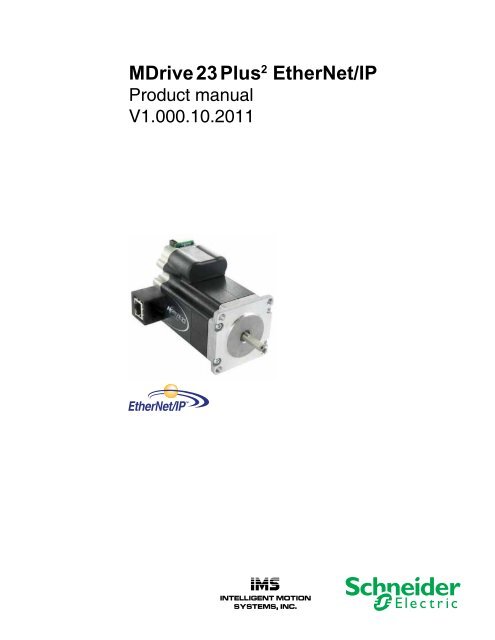
<strong>MDrive</strong> <strong>23</strong> Plus 2 <strong>EtherNet</strong>/<strong>IP</strong><br />
Product manual<br />
V1.000.10.2011<br />
TM
<strong>MDrive</strong>Plus <strong>EtherNet</strong>/<strong>IP</strong> Manual<br />
Date Revision Changes<br />
10/12/2011 V1.000.10.2011 Initial Release<br />
The information in IMS Schneider Electric <strong>Motion</strong> USA product documentation<br />
and on this web site has been carefully checked and is<br />
believed to be accurate; however, no responsibility is assumed for inaccuracies.<br />
IMS Schneider Electric <strong>Motion</strong> USA reserves the right to make changes<br />
without further notice to any products to improve reliability, function<br />
or design. IMS Schneider Electric <strong>Motion</strong> USA does not assume any<br />
liability arising out of the application or use of any product or circuit<br />
described; neither does it convey any license under its patent rights of<br />
others.<br />
IMS Schneider Electric <strong>Motion</strong> USA’s general policy does not recommend<br />
the use of its products in life support or aircraft applications<br />
wherein a failure or malfunction of the product may directly threaten life<br />
or injury. Per the terms and conditions of sales of IMS Schneider Electric<br />
<strong>Motion</strong> USA, the user of IMS Schneider Electric <strong>Motion</strong> USA products<br />
in life support or aircraft applications assumes all risks of such use and<br />
indemnifi es IMS Schneider Electric <strong>Motion</strong> USA against all damages.<br />
aircraft applications assumes all risks of such use and indemnifi es IMS<br />
Schneider Electric <strong>Motion</strong> USA against all damages.<br />
<strong>MDrive</strong>Plus <strong>EtherNet</strong>/<strong>IP</strong> Manual V1.00, 10.2011<br />
Copyright © Schneider Electric <strong>Motion</strong> USA, All Rights Reserved
Important information<br />
This manual is part of the product.<br />
Carefully read this manual and observe all instructions.<br />
Keep this manual for future reference.<br />
Hand this manual and all other pertinent product documentation over to all<br />
users of the product.<br />
Carefully read and observe all safety instructions and the chapter “Before<br />
you begin - safety information”.<br />
Some products are not available in all countries.<br />
For information on the availability of products, please consult the catalog.<br />
Subject to technical modifi cations without notice.<br />
All details provided are technical data which do not constitute warranted<br />
qualities.<br />
Most of the product designations are registered trademarks of their<br />
respective owners, even if this is not explicitly indicated.
This page intentionally left blank
V1.000, 10.2011<br />
<strong>MDrive</strong>Plus <strong>EtherNet</strong>/<strong>IP</strong> Table of Contents<br />
Table of Contents<br />
Important information .................................................................... 3<br />
Writing conventions and symbols .............................................. 1<br />
1 Introduction ................................................................................... 3<br />
1.1 About this manual ............................................................... 3<br />
1.2 Unit overview ...................................................................... 3<br />
1.3 Components and interfaces ............................................... 4<br />
1.3.1 Components ......................................................... 4<br />
1.3.2 Interfaces .............................................................. 5<br />
1.4 Name plate ......................................................................... 6<br />
1.5 Part number identifi cation ................................................... 7<br />
1.6 Documentation and literature references ........................... 8<br />
2 Before you begin - safety information ........................................ 9<br />
2.1 Qualifi cation of personnel ................................................... 9<br />
2.2 Intended use ....................................................................... 9<br />
2.3 Hazard categories ............................................................ 10<br />
2.4 Basic information .............................................................. 11<br />
2.5 Standards and terminology ................................................... 13<br />
3 Technical data ............................................................................. 15<br />
3.1 Environmental conditions ................................................. 15<br />
3.2 Mechanical data ............................................................... 16<br />
3.2.1 Degree of protection ........................................... 16<br />
3.2.2 Mounting position ................................................ 17<br />
3.2.3 Dimensions (rotary shaft) .................................... 17<br />
3.2.4 Dimensions (linear actuator) ............................... 18<br />
3.2.5 Lineal Actuator screw and nut specifi cations ...... 18<br />
3.3 Electrical data ................................................................... 20<br />
3.3.1 Supply voltage VDC at P3 ................................... 20<br />
3.3.2 I/O interface at P1 ............................................... 21<br />
3.3.3 Fieldbus interface at P2 ...................................... <strong>23</strong><br />
3.4 Rotary motor data ............................................................. 24<br />
3.4.1 Specifi cations ...................................................... 24<br />
3.4.2 Performance curves ............................................ 24<br />
3.5 Linear actuator data ......................................................... 25<br />
3.5.1 Specifi cations ...................................................... 25<br />
3.5.2 Linear performance curves ................................. 25<br />
4 Basics .......................................................................................... 27<br />
4.1 Functional safety .............................................................. 27<br />
4.1.1 Working with IEC 61508 ..................................... 27<br />
5 Engineering ................................................................................. 29<br />
5.1 External power supply units ............................................. 29<br />
5.1.1 Supply voltage .................................................... 29<br />
5.2 Ground design .................................................................. 31<br />
5.3 Monitoring functions ......................................................... 32<br />
i
V1.000, 10.2011<br />
Table of Contents<br />
ii<br />
<strong>MDrive</strong>Plus <strong>EtherNet</strong>/<strong>IP</strong><br />
6 Installation ................................................................................... 33<br />
6.1 Electromagnetic compatibility, EMC ................................. 34<br />
6.2 Mechanical installation ..................................................... 35<br />
6.3 Electrical installation ......................................................... 38<br />
6.3.1 Overview of all connectors .................................. 39<br />
6.3.2 Connection of the supply voltage VDC .......39<br />
6.3.3 Connection of the I/O interface ........................... 43<br />
6.3.4 Connection of the fi eldbus interface ................... 49<br />
6.4 Checking wiring ................................................................ 50<br />
7 Commissioning ........................................................................... 51<br />
7.1 Preparing for commissioning ............................................ 53<br />
7.1.1 Installing the TCP/<strong>IP</strong> Confi guration Utility ........... 53<br />
7.2 Commissioning fi eldbus parameters ................................ 54<br />
7.2.1 <strong>IP</strong> Address and subnet mask .............................. 54<br />
8 Operation ..................................................................................... 55<br />
8.1 Basics ............................................................................... 55<br />
8.1.1 Overview ............................................................. 55<br />
8.2 Supported objects ............................................................ 56<br />
8.2.1 Standard objects ................................................. 56<br />
8.2.2 Manufacturer specifi c objects ............................. 56<br />
9 Diagnostics and troubleshooting ............................................. 57<br />
9.1 Fieldbus communication error diagnostics ....................... 57<br />
9.2 Status LEDs ..................................................................... 58<br />
10 Accessories and spare parts ..................................................... 59<br />
10.1 Accessories ...................................................................... 59<br />
11 Service, maintenance and disposal .......................................... 61<br />
11.1 Service address ................................................................ 62<br />
11.2 Maintenance ..................................................................... 62<br />
11.3 Replacing units ................................................................. 62<br />
11.4 Shipping, storage, disposal .............................................. 63<br />
12 Glossary ...................................................................................... 65<br />
12.1 Units and conversion tables ............................................. 65<br />
12.1.1 Length ................................................................. 65<br />
12.1.2 Mass ................................................................... 65<br />
12.1.3 Force ................................................................... 65<br />
12.1.4 Power .................................................................. 66<br />
12.1.5 Rotation .............................................................. 66<br />
12.1.6 Torque ................................................................ 66<br />
12.1.7 Moment of inertia ................................................ 66<br />
12.1.8 Temperature ....................................................... 66<br />
12.1.9 Conductor cross section ..................................... 67<br />
12.2 Terms and Abbreviations ................................................. 67
V1.000, 10.2011<br />
<strong>MDrive</strong>Plus <strong>EtherNet</strong>/<strong>IP</strong> Table of Contents<br />
List of Figures<br />
Figure 1.1: Components and Interfaces ........................................ 4<br />
Figure 1.2: Name plate .................................................................. 5<br />
Figure 1.3: Part numbering ........................................................... 7<br />
Figure 3.1: Mounting positions .................................................... 17<br />
Figure 3.2: Dimensions [inches (mm)] ........................................ 17<br />
Figure 3.3: <strong>MDrive</strong> <strong>23</strong> Linear Actuator dimensions .................... 18<br />
Figure 3.4: Linear Actuator screw specifi cations [inches (mm)] .. 18<br />
Figure 3.5: Linear Actuator nut specifi cations [inches (mm)] ...... 19<br />
Figure 3.6: Overview of connectors ............................................ 20<br />
Figure 3.7: Speed Torque Curves ............................................... 24<br />
Figure 3.8: Linear speed force curves......................................... 25<br />
Figure 6.1: Overview of connectors ............................................ 39<br />
Figure 6.2: Pin Assignment supply voltage ................................. 41<br />
Figure 6.3: Connecting supply voltage VDC wiring ..................... 42<br />
Figure 6.4: I/O interface pin assignments ................................... 43<br />
Figure 6.5: Connecting I/O interface wiring ................................. 44<br />
Figure 6.6: Switched sinking input .............................................. 45<br />
Figure 6.7: NPN sinking input ..................................................... 45<br />
Figure 6.8: PNP sourcing input ................................................... 45<br />
Figure 6.9: Sinking output to an inductive load ........................... 46<br />
Figure 6.10: Sinking output to an LED ........................................ 46<br />
Figure 6.11: Sourcing output to inductive lo ................................ 46<br />
Figure 6.12: Clock I/O equivalent circuit ..................................... 47<br />
Figure 6.13: Capture/Trip I/O equivalent circuit ......................... 47<br />
Figure 6.14: Analog input ............................................................ 48<br />
Figure 6.15: Fieldbus interface pin assignments......................... 49<br />
Figure 7.1: Confi guration tab ....................................................... 54<br />
Figure 8.1: <strong>EtherNet</strong>/<strong>IP</strong> network .................................................. 55<br />
Figure 9.1: Status indicator LEDs ............................................... 58<br />
iii
V1.000, 10.2011<br />
Table of Contents<br />
iv<br />
Page intentionally left blank<br />
<strong>MDrive</strong>Plus <strong>EtherNet</strong>/<strong>IP</strong>
V1.000, 10.2011<br />
<strong>MDrive</strong>Plus <strong>EtherNet</strong>/<strong>IP</strong> Writing conventions and symbols<br />
Writing conventions and symbols<br />
Integrated <strong>Motion</strong> System<br />
Work steps If work steps must be performed consecutively, this sequence of steps is<br />
represented as follows:<br />
� Special prerequisites for the following work steps<br />
� Step 1<br />
� Specific response to this work step<br />
� Step 2<br />
If a response to a work step is indicated, this allows you to verify that the<br />
work step has been performed correctly.<br />
Unless otherwise stated, the individual steps must be performed in the<br />
specified sequence.<br />
Bulleted lists The items in bulleted lists are sorted alphanumerically or by priority. Bulleted<br />
lists are structured as follows:<br />
• Item 1 of bulleted list<br />
• Item 2 of bulleted list<br />
– Subitem for 2<br />
– Subitem for 2<br />
• Item 3 of bulleted list<br />
Making work easier Information on making work easier is highlighted by this symbol:<br />
Sections highlighted this way provide supplementary information on<br />
making work easier.<br />
Parameters Parameters are shown as follows<br />
RC Motor Run Current<br />
Units of measure Measurements are given US units, metric values are given in SI units in<br />
parenthesis.<br />
Examples”<br />
1.00 in (25.4 mm)<br />
100 oz-in (70 N-cm)<br />
1
V1.000, 10.2011<br />
Writing conventions and symbols<br />
2<br />
Page intentionally left blank<br />
<strong>MDrive</strong>Plus <strong>EtherNet</strong>/<strong>IP</strong><br />
Integrated <strong>Motion</strong> System
V1.000, 10.2011<br />
<strong>MDrive</strong>Plus <strong>EtherNet</strong>/<strong>IP</strong> 1 Introduction<br />
1 Introduction<br />
1.1 About this manual<br />
1.2 Unit overview<br />
Integrated <strong>Motion</strong> System<br />
This manual is valid for all <strong>MDrive</strong><strong>23</strong>Plus standard products with <strong>EtherNet</strong>/<strong>IP</strong><br />
industrial protocol. This chapter lists the type code for this<br />
product. The type code can be used to identify whether your product is a<br />
standard product or a customized model.<br />
The “\<strong>MDrive</strong>Plus <strong>EtherNet</strong>/<strong>IP</strong> consists of a stepper motor and integrated<br />
electronics. The product integrates interfaces, drive and control electronics<br />
and the power stage. Available protocols are <strong>EtherNet</strong>/<strong>IP</strong> industrial<br />
protocol, MODBUS/TCP, MCode/TCP on a single device.<br />
All setup parameters are set via the fieldbus interface.<br />
1<br />
3
V1.000, 10.2011<br />
1 Introduction<br />
1.3 Components and interfaces<br />
1.3.1 Components<br />
4<br />
C<br />
D<br />
E<br />
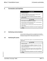
Figure 1.1: Components and Interfaces<br />
(A) Electronics housing<br />
(B) Two phase stepper motor<br />
(C) DC power and I/O interface<br />
(D) Ethernet<br />
(E) LED indicators<br />
A<br />
<strong>MDrive</strong>Plus <strong>EtherNet</strong>/<strong>IP</strong><br />
Motor The motor is a two phase brushless stepper motor. The motor has a<br />
high torque density due to the use of the latest magnetic materials and<br />
enhanced design. The step angle of the motor is 1.8°.<br />
Electronics housing The electronics system is comprised of control electronics and power<br />
stage.<br />
The drive system is controlled by streaming commands via the Ethernet<br />
interface using the <strong>EtherNet</strong>/<strong>IP</strong> standard and manufacturer specific<br />
object classes.<br />
B<br />
Integrated <strong>Motion</strong> System
V1.000, 10.2011<br />
<strong>MDrive</strong>Plus <strong>EtherNet</strong>/<strong>IP</strong> 1 Introduction<br />
1.3.2 Interfaces<br />
Integrated <strong>Motion</strong> System<br />
Standard available interfaces.<br />
DC power supply voltage The supply voltage VDC supplies the drive and control electronics and<br />
the power stage.<br />
The ground connections of all interfaces are galvanically connected.<br />
For more information see chapter 5.2 “Ground design”. This chapter<br />
also provides information on protection against reverse polarity.<br />
I/O interface The I/O interface operates at the following signal levels:<br />
• 12 to 24V Aux-Power input to supply power to logic circuits in<br />
the event of main supply loss.<br />
• 4 - 24V I/O points configurable as input or output<br />
• 1 TTL level high speed input configurable as capture input or a<br />
trip output<br />
• 10-bit analog input signal<br />
The 24V signals are programmable as general purpose or to predefined<br />
input or output functions.<br />
The reference voltage or current is applied to the analog input can be<br />
used for a number of programmatically defined operations.<br />
Ethernet interface The Ethernet interface provides a connection to the <strong>EtherNet</strong> network..<br />
A PC may be connected to the interface via CAT5/6 cabling and RJ45<br />
connectors. The commissioning software may then be used for tasks<br />
such as configuring the <strong>IP</strong> and gateway address and mapping the Assembly<br />
object (0x04).<br />
The Ethernet interface is also used for firmware upgrades.<br />
5
V1.000, 10.2011<br />
1 Introduction<br />
1.4 Name plate<br />
6<br />
<strong>MDrive</strong>Plus <strong>EtherNet</strong>/<strong>IP</strong><br />
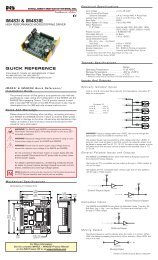
The product label is located on the underside of the electronics housing<br />
and has the following information<br />
1<br />
2<br />
Figure 1.2: Name plate<br />
MDI3CIR<strong>23</strong>A7-EQ<br />
341070398<br />
V4.0.04<br />
(1) Part number<br />
(2) Datamatrix containing all pertinent information about the device<br />
(3) Serial number<br />
(4) Firmware revision<br />
Integrated <strong>Motion</strong> System<br />
3<br />
4
V1.000, 10.2011<br />
<strong>MDrive</strong>Plus <strong>EtherNet</strong>/<strong>IP</strong> 1 Introduction<br />
1.5 Part number identifi cation<br />
Integrated <strong>Motion</strong> System<br />
Product<br />
MDI = <strong>MDrive</strong>Plus<br />
Communication interface<br />
3 = Expanded I/O features<br />
Power and I/O connector style<br />
C = Wire crimp style<br />
Fieldbus protocol<br />
I = Ethernet/<strong>IP</strong><br />
Fieldbus connector style<br />
R = RJ45<br />
Motor<br />
<strong>23</strong> = NEMA <strong>23</strong> size/57 mm<br />
Motor length<br />
A = Single<br />
B = Double<br />
C = Triple<br />
D = Quad<br />
Input voltage<br />
7 = 75 VDC (<strong>MDrive</strong>Plus A, B, C lengths)<br />
6 = 60 VDC (<strong>MDrive</strong>Plus D length<br />
Internal magnetic encoder<br />
EQ = 512 lines/2048 edges (optional)<br />
MDI 3 C I R <strong>23</strong> A 7 - EQ<br />
Figure 1.3: Part numbering<br />
7
V1.000, 10.2011<br />
1 Introduction<br />
1.6 Documentation and literature references<br />
8<br />
<strong>MDrive</strong>Plus <strong>EtherNet</strong>/<strong>IP</strong><br />
This document should be used in conjunction with the following product<br />
manuals.<br />
• <strong>EtherNet</strong>/<strong>IP</strong> Fieldbus Manual<br />
• MCode Programming and Software Reference Manual<br />
Source product manuals The current product manuals are available for download from the Internet.<br />
http://www.schneider-electric-motion.us<br />
Integrated <strong>Motion</strong> System
V1.000, 10.2011<br />
<strong>MDrive</strong>Plus <strong>EtherNet</strong>/<strong>IP</strong> 2 Before you begin - safety information<br />
2 Before you begin - safety information<br />
2.1 Qualifi cation of personnel<br />
2.2 Intended use<br />
Integrated <strong>Motion</strong> System<br />
2<br />
The information provided in this manual supplements the product<br />
manual. Carefully read the product manual before using the product.<br />
Only appropriately trained persons who are familiar with and understand<br />
the contents of this manual and all other pertinent product documentation<br />
are authorized to work on and with this product. In addition, these<br />
persons must have received safety training to recognize and avoid<br />
hazards involved. These persons must have sufficient technical training,<br />
knowledge and experience and be able to foresee and detect potential<br />
hazards that may be caused by using the product, by changing the settings<br />
and by the mechanical, electrical and electronic equipment of the<br />
entire system in which the product is used.<br />
All persons working on and with the product must be fully familiar with<br />
all applicable standards, directives, and accident prevention regulations<br />
when performing such work.<br />
The functions described in this manual are only intended for use with the<br />
basic product; you must read and understand the appropriate product<br />
manual.<br />
The product may only be used in compliance with all applicable safety<br />
regulations and directives, the specified requirements and the technical<br />
data.<br />
Prior to using the product, you must perform a risk assessment in view<br />
of the planned application. Based on the results, the appropriate safety<br />
measures must be implemented.<br />
Since the product is used as a component in an entire system, you must<br />
ensure the safety of persons by means of the design of this entire system<br />
(for example, machine design).<br />
Operate the product only with the specified cables and accessories. Use<br />
only genuine accessories and spare parts.<br />
Any use other than the use explicitly permitted is prohibited and can<br />
result in hazards.<br />
Electrical equipment should be installed, operated, serviced, and maintained<br />
only by qualified personnel.<br />
The product must NEVER be operated in explosive atmospheres (hazardous<br />
locations, Ex areas).<br />
9
V1.000, 10.2011<br />
2 Before you begin - safety information<br />
2.3 Hazard categories<br />
10<br />
<strong>MDrive</strong>Plus <strong>EtherNet</strong>/<strong>IP</strong><br />
Safety instructions to the user are highlighted by safety alert symbols<br />
in the manual. In addition, labels with symbols and/or instructions<br />
are attached to the product that alert you to potential hazards.<br />
Depending on the seriousness of the hazard, the safety instructions<br />
are divided into 4 hazard categories.<br />
DANGER indicates an imminently hazardous situation, which,<br />
if not avoided, will result in death or serious injury.<br />
WARNING indicates a potentially hazardous situation, which, if<br />
not avoided, can result in death, serious injury, or equipment<br />
damage.<br />
CAUTION indicates a potentially hazardous situation, which, if<br />
not avoided, can result in injury or equipment damage.<br />
CAUTION used without the safety alert symbol, is used to address<br />
practices not related to personal injury (e.g. can result in<br />
equipment damage).<br />
Integrated <strong>Motion</strong> System
V1.000, 10.2011<br />
<strong>MDrive</strong>Plus <strong>EtherNet</strong>/<strong>IP</strong> 2 Before you begin - safety information<br />
2.4 Basic information<br />
Integrated <strong>Motion</strong> System<br />
UNINTENDED CONSEQUENCES OF EQU<strong>IP</strong>MENT OPERATION<br />
When the system is started, the drives are usually out of the<br />
operator’s view and cannot be visually monitored.<br />
• Only start the system if there are no persons in the hazardous<br />
area.<br />
Failure to follow these instructions will result in death or<br />
serious injury.<br />
UNEXPECTED MOVEMENT<br />
Drives may perform unexpected movements because of incorrect<br />
wiring, incorrect settings, incorrect data or other errors.<br />
Interference (EMC) may cause unpredictable responses in the<br />
system.<br />
• Carefully install the wiring in accordance with the EMC<br />
requirements.<br />
• Ensure the BRIDGE ENABLE input is inactive to avoid an<br />
unexpected restart of the motor before switching on and<br />
confi guring the drive system.<br />
• Do NOT operate the drive system with unknown settings<br />
or data.<br />
• Perform a comprehensive commissioning test.<br />
Failure to follow these instructions can result in death or<br />
serious injury.<br />
11
V1.000, 10.2011<br />
2 Before you begin - safety information<br />
12<br />
LOSS OF CONTROL<br />
<strong>MDrive</strong>Plus <strong>EtherNet</strong>/<strong>IP</strong><br />
• The designer of any control scheme must consider the<br />
potential failure modes of control paths and, for certain<br />
critical functions, provide a means to achieve a safe state<br />
during and after a path failure. Examples of critical control<br />
functions are emergency stop, overtravel stop, power outage<br />
and restart.<br />
• Separate or redundant control paths must be provided for<br />
critical functions.<br />
• System control paths may include communication links.<br />
Consideration must be given to the implication of unanticipated<br />
transmission delays or failures of the link.<br />
• Observe all accident prevention regulations and local<br />
safety guidelines. 1)<br />
• Each implementation of the product must be individually<br />
and thoroughly tested for proper operation before being<br />
placed into service.<br />
Failure to follow these instructions can result in death or<br />
serious injury.<br />
1) For USA: Additional information, refer to NEMA ICS 1.1 (latest edition), “Safety<br />
Guidelines for the Application, Installation, and Maintenance of Solid State Control”<br />
and to NEMA ICS 7.1 (latest edition), “Safety Standards for Construction and Guide<br />
for Selection, Installation and Operation of Adjustable-Speed Drive Systems”.<br />
UNEXPECTED BEHAVIOR AND DESTRUCTION OF SYS-<br />
TEM COMPONENTS<br />
When you work on the wiring and when you unplug or plug in<br />
connectors, this may cause unexpected behavior and destruction<br />
of system components.<br />
• Switch the power supply off before working on the wiring.<br />
Failure to follow these instructions can result in injury or<br />
equipment damage.<br />
Integrated <strong>Motion</strong> System
V1.000, 10.2011<br />
<strong>MDrive</strong>Plus <strong>EtherNet</strong>/<strong>IP</strong> 2 Before you begin - safety information<br />
2.5 Standards and terminology<br />
Integrated <strong>Motion</strong> System<br />
Technical terms, terminology and the corresponding descriptions in<br />
this manual are intended to use the terms or definitions of the pertinent<br />
standards.<br />
In the area of drive systems, this includes, but is not limited to, terms<br />
such as “safety function”, “safe state”, “fault”, “fault reset”, “failure”, “error”,<br />
“error message”, “warning”, “warning message”, etc.<br />
Among others, these standards include:<br />
• IEC 61800 series: “Adjustable speed electrical power drive<br />
systems”<br />
• IEC 61800-7 series: “Adjustable speed electrical power drive<br />
systems - Part 7-1: Generic interface and use of profiles for<br />
power drive systems - Interface definition”<br />
• IEC 61158 series: “Industrial communication networks - Fieldbus<br />
specifications”<br />
• IEC 61784 series: “Industrial communication networks - Profiles”<br />
• IEC 61508 series: “Functional safety of electrical/electronic/programmable<br />
electronic safety-related systems”<br />
13
V1.000, 10.2011<br />
2 Before you begin - safety information<br />
14<br />
Page intentionally left blank<br />
<strong>MDrive</strong>Plus <strong>EtherNet</strong>/<strong>IP</strong><br />
Integrated <strong>Motion</strong> System
V1.000, 10.2011<br />
<strong>MDrive</strong>Plus <strong>EtherNet</strong>/<strong>IP</strong> 3 Technical data<br />
3 Technical data<br />
3.1 Environmental conditions<br />
Integrated <strong>Motion</strong> System<br />
This chapter contains information on the ambient conditions and on the<br />
mechanical and electrical properties of the device family and the accessories.<br />
Ambient operating conditions The maximum permissible ambient temperature during operation<br />
depends on the distance between the devices and the required power.<br />
Observe the pertinent instructions in the chapter Installation.<br />
Ambient conditions: transportation and<br />
storage<br />
The following relative humidity is permissible during operation.<br />
Operating temperature [°C] -20 ... 50 (no icing)<br />
Temperature variation [°C/min] 0.5<br />
Humidity [%] 5 ... 95 (non-condensing)<br />
The environment during transport and storage must be dry and free from<br />
dust. The maximum vibration and shock load must be within the specified<br />
limits.<br />
Temperature [°C] -25 ... 70<br />
Temperature variation [°C] -25 ... 30<br />
Humidity [%] 5 ... 95 (non-condensing)<br />
3<br />
15
V1.000, 10.2011<br />
3 Technical data<br />
16<br />
Maximum operating temperatures Power stage 1) [°C] 85<br />
3.2 Mechanical data<br />
3.2.1 Degree of protection<br />
Motor 2) [°C] 100<br />
1) May be read via parameter<br />
2) Measured on the surface<br />
<strong>MDrive</strong>Plus <strong>EtherNet</strong>/<strong>IP</strong><br />
Installation altitude The installation altitude is defined as height above sea level<br />
Vibration and shock Vibration, sinusoidal<br />
Installation altitude 1) [ft (m)] 3280 (1000)<br />
3) Installation above 3280 (1000) may require derating output current and<br />
maximum ambient temperature.<br />
Shock, non-sinusoidal<br />
EMC Emission EIC61800-3 (Category C2)<br />
Noise immunity IEC61000-6-2<br />
<strong>IP</strong> degree of protection The product has the following <strong>IP</strong> degree of protection as per EN 60529.<br />
Degree of protection <strong>IP</strong>20<br />
The total degree of protection is determined by the component with the<br />
lowest degree of protection.<br />
<strong>IP</strong> degrees of protection overview First digit<br />
Second digit<br />
Protection against intrusion of<br />
objects<br />
Protection against intrusion of water<br />
0 No protection 0 No protection<br />
1 External objects >50 mm 1 Vertically falling dripping water<br />
2 External objects >12 mm 2 Dripping water falling at an angle<br />
(75 ° ... 90 °)<br />
3 External objects >2.5 mm 3 Spraying water<br />
4 External objects >1 mm 4 Splashing water<br />
5 Dust-protected 5 Water jets<br />
6 Dust-tight 6 Heavy sea<br />
7 Immersion<br />
8 Submersion<br />
Integrated <strong>Motion</strong> System
V1.000, 10.2011<br />
<strong>MDrive</strong>Plus <strong>EtherNet</strong>/<strong>IP</strong> 3 Technical data<br />
3.2.2 Mounting position<br />
3.2.3 Dimensions (rotary shaft)<br />
2.96<br />
(75.2)<br />
P1/P3<br />
1.90<br />
(48.3)<br />
1.34<br />
(34.0)<br />
Integrated <strong>Motion</strong> System<br />
P2<br />
L MAX<br />
0.063 ±0.008<br />
(1.6 ±0.2)<br />
Motor stack length Lmax<br />
Single 2.65 (67.31)<br />
Double 3.02 (76.71)<br />
Triple 3.88 (98.55)<br />
Quad 5.28 (134.15)<br />
The following mounting positions are defined and approved as per EN<br />
60034-7:<br />
• IM B5 drive shaft horizontal<br />
• IM V1 drive shaft vertical, shaft end down<br />
• IM V3 drive shaft vertical, shaft end up<br />
IM B5<br />
Figure 3.1: Mounting positions<br />
0.189 ±0.012<br />
(4.8 ±0.3)<br />
0.81 ±0.02<br />
(20.6 ±0.5)<br />
0.59 ±0.008<br />
(15.0 ±0.2)<br />
Single, Double & Triple<br />
Length Motors:<br />
0.<strong>23</strong>0 ±0.004<br />
(5.8 ±0.1)<br />
Quad Length Motor:<br />
0.2756 ±0.004<br />
(7.0 ±0.1)<br />
Single, Double & Triple<br />
Length Motors:<br />
Ø 0.2500 +0/-0.0005<br />
(Ø 6.350 +0/-0.013)<br />
Quad Length Motor:<br />
Ø 0.315 +0/-0.0005<br />
(Ø 8.0 +0/-0.013)<br />
� 0.93<br />
(� <strong>23</strong>.6)<br />
0.86*<br />
(21.8)<br />
Figure 3.2: Dimensions [inches (mm)]<br />
IM V1 IM V3<br />
2.02<br />
(51.2)<br />
1.63<br />
(41.4)<br />
� 2.22<br />
(� 56.4)<br />
Ø 0.197 +0.012/-0<br />
(Ø 5.0 +0.3/-0)<br />
� 1.856 ±0.008<br />
(� 47.1 ±0.2)<br />
Ø 1.500 ±0.002<br />
(Ø 38.1 ±0.1)<br />
17
V1.000, 10.2011<br />
3 Technical data<br />
3.2.4 Dimensions (linear actuator)<br />
18<br />
2.96<br />
(75.2)<br />
External shaft<br />
P1/P3<br />
P2<br />
1.90<br />
(48.3)<br />
1.34<br />
(34.0)<br />
2.65<br />
(67.31)<br />
0.06 ±0.00<br />
(1.5 ±0.1)<br />
0.19<br />
(4.9)<br />
3.0 to 24.0<br />
(77.5 to 610.0)<br />
0.50<br />
(12.7)<br />
0.375<br />
(9.525)<br />
® Loads for external shaft <strong>MDrive</strong> linear actuator products MUST BE supported. Side loading is not recommended.<br />
3.2.5 Lineal Actuator screw and nut specifi cations<br />
Nut<br />
<strong>MDrive</strong>Plus <strong>EtherNet</strong>/<strong>IP</strong><br />
2.02<br />
(51.2)<br />
1.63<br />
(41.4)<br />
1.856 ±0.008<br />
( 47.1 ±0.2)<br />
2.22<br />
( 56.4)<br />
Figure 3.3: <strong>MDrive</strong> <strong>23</strong> Linear Actuator dimensions [inches (mm)]<br />
0.375<br />
(9.52)<br />
3.0 to 24.0<br />
(77.5 to 610.0)<br />
Screw end option details below<br />
Straightness 0.002 (0.05)<br />
Threaded end Smooth end None<br />
Figure 3.4: Linear Actuator screw specifications [inches (mm)]<br />
P3<br />
Ø 0.197 +0.012/-0<br />
(Ø 5.0 +0.3/-0)<br />
Ø 1.500 ±0.002<br />
(Ø 38.1 ±0.1)<br />
0.50<br />
(12.7)<br />
<strong>MDrive</strong> Linear Actuator precision rolled lead screws are designed specifi<br />
cally for motion control applications to deliver maximum life and quiet<br />
operation. Corrosion resistant and non-magnetic, screws are manufactured<br />
from premium grade stainless steel.<br />
Integrated <strong>Motion</strong> System
V1.000, 10.2011<br />
<strong>MDrive</strong>Plus <strong>EtherNet</strong>/<strong>IP</strong> 3 Technical data<br />
Integrated <strong>Motion</strong> System<br />
An optional Tefl on® screw coating is available for smooth operation<br />
and extended life.<br />
Leadscrew pitch information travel per revolution travel per full step<br />
Leadscrew end options<br />
External Linear Actuator nut specifi cations<br />
Nut outline<br />
Screw G 0.3750 (9.525) 0.001875 (0.0476)<br />
Screw A 0.200 (5.08) 0.001 (0.0254)<br />
Screw B 0.1670 (4.<strong>23</strong>3) 0.000835 (0.0212)<br />
Screw D 0.0833 (2.116) 0.0004165 (0.0106)<br />
Threaded<br />
Smooth<br />
None<br />
Metric M6 x 1.0 mm thread to within 0.03” / 0.76 mm of<br />
shoulder<br />
UNC 1/4-20 UNC-2A thread to within 0.05” / 1.3 mm of<br />
shoulder<br />
Ø D<br />
Inches Ø 0.<strong>23</strong>62 ±0.001<br />
mm Ø 6 ±0.003<br />
Ø BCD<br />
Ø E<br />
–<br />
General purpose nut Anti-backlash nut<br />
Figure 3.5: Linear Actuator nut specifications [inches (mm)]<br />
F<br />
Dimension - in (mm) General purpose nut Anti-backlash nut<br />
A 0.71 (18.0) 0.82 (20.8)<br />
B<br />
B 1.50 (38.1) 1.875 max (47.63 max)<br />
D 1.50 (38.1) 1.50 (38.1)<br />
E 0.20 (5.08) 0.20 (5.08)<br />
F 0.20 (5.08) 0.20 (5.08)<br />
BCD 1.125 (28.6) 1.125 (28.6)<br />
Load limit - lbs (kg) 60 (27) 25 (11)<br />
Drag torque free wheeling 1 to 3<br />
A<br />
F<br />
B<br />
A<br />
19
V1.000, 10.2011<br />
3 Technical data<br />
3.3 Electrical data<br />
20<br />
Overview of connectors<br />
3.3.1 Supply voltage VDC at P3<br />
Motor<br />
Shaft<br />
P1<br />
14 12 10 8 6 4 2<br />
13 11 9 7 5 3 1<br />
P2<br />
Top-Rear view<br />
Motor<br />
Shaft<br />
Side view<br />
Figure 3.6: Overview of connectors<br />
1<br />
2<br />
3<br />
4<br />
5<br />
6<br />
7<br />
8<br />
P3<br />
SWITCHING DC/HOT PLUGGING!<br />
1<br />
2<br />
<strong>MDrive</strong>Plus <strong>EtherNet</strong>/<strong>IP</strong><br />
Do not connect or disconnect power, logic, or communication<br />
while the device is in a powered state.<br />
Remove DC power by powering down at the AC side of the DC<br />
power supply.<br />
Failure to follow these instructions may result in damage<br />
to system components!<br />
MDI MDI (quad)<br />
Limit values min/max 1) [+Vdc ] 12/75 12/60<br />
Ripple at nominal voltage [%] 5 5<br />
Max. current input [A] 2.0 3.5<br />
Fuse to be connected upstream 2) [A]<br />
1) The actual power requirement is often significantly lower, because the<br />
maximum possible motor torque is usually not required for operation of a<br />
system.<br />
2) See chapter 5.1.1 “Supply voltage”<br />
NOTE: To facilitate switching DC, a protection module, the DPM75 is<br />
available. See Section 10.<br />
Integrated <strong>Motion</strong> System
V1.000, 10.2011<br />
<strong>MDrive</strong>Plus <strong>EtherNet</strong>/<strong>IP</strong> 3 Technical data<br />
3.3.2 I/O interface at P1<br />
Integrated <strong>Motion</strong> System<br />
General purpose I/O<br />
ELECTRICAL OVERSTRESS<br />
The general purpose I/O is tolerant to +24 VDC. The following<br />
listed I/O points are TTL level and only tolerant to +5 VDC:<br />
1) Capture/Trip<br />
2) Step<br />
3) Direction<br />
Do not exceed +5 VDC on this point.<br />
Failure to follow these instructions may result in damage<br />
to system components!<br />
The signal I/O functions are programmable in function. They may be<br />
used as sinking or sourcing inputs or outputs.<br />
Configured as inputs<br />
Voltage range [+V dc ] 5 ... 24<br />
Configured as outputs<br />
Voltage rating Sinking [V dc ] +24<br />
Sourcing [V dc ] +12 ... +24<br />
Current rating (one channel) [mA] 600<br />
Protection Sinking Over temp, short circuit<br />
Sourcing Transient over voltage, inductive clamp<br />
Analog input Voltage mode 0 - 5 [V dc ] 0 ... 5<br />
Voltage mode 0 - 10 [V dc ] 0 ... 10<br />
Current loop mode [mA] 4 ... 20<br />
0 ... 20<br />
Resolution [Bits] 10<br />
21
V1.000, 10.2011<br />
3 Technical data<br />
22<br />
<strong>MDrive</strong>Plus <strong>EtherNet</strong>/<strong>IP</strong><br />
Capture/trip I/O One high speed I/O point may be configured as either a capture input or<br />
a trip output.<br />
Configured as Capture input<br />
Voltage [V dc ] 5<br />
Resolution [bits] 32<br />
Filter range 50 nS ... 12.9 μS<br />
10 MHz ... 38.8 kHz<br />
Configured as Trip output<br />
Voltage (with 2kΩ load to ground) [V dc ] 5<br />
Resolution [bits] 32<br />
Speed [nS] 150<br />
Step/direction I/O Two high speed I/O points are TTL level dedicated as Step and Direction<br />
I/O. They may be configured as either<br />
• Inputs, for following the step pulses and direction control of<br />
master controller for electronic gearing.<br />
• Outputs: which allows the device to operate as a master controller<br />
driving a following axis.<br />
Configured as input<br />
Voltage [V dc ] 5<br />
Resolution [bits] 32<br />
Input frequency (max) [MHz] 5<br />
Input ratio range 0.001 ... 2.000<br />
Filter range 50 nS ... 12.9 μS<br />
10 MHz ... 38.8 kHz<br />
Configured as output<br />
Voltage (with 2kΩ load to ground) [V dc ] 5<br />
Resolution [bits] 32<br />
Output frequency (max) [MHz] 5<br />
Output ratio 1:1<br />
Speed [nS] 150<br />
Integrated <strong>Motion</strong> System
V1.000, 10.2011<br />
<strong>MDrive</strong>Plus <strong>EtherNet</strong>/<strong>IP</strong> 3 Technical data<br />
Integrated <strong>Motion</strong> System<br />
Auxiliary supply voltage VDC Aux power is used to maintain power to the logic circuits and retain<br />
information stored in counters, registers and user variable in the event<br />
of system power loss. It is not a required connection.<br />
3.3.3 Fieldbus interface at P2<br />
NOTE: The Auxiliary power input will not provide power to the communication<br />
interface. In the event of main power loss control commands to<br />
the device will not be processed.<br />
Limit values min/max [+Vdc ] 12/24<br />
Max. current input [mA] 194<br />
Ethernet Characteristic Ethernet RJ45<br />
Baud rate [Mbps] 10 ... 100<br />
Protocols <strong>EtherNet</strong>/<strong>IP</strong><br />
Port 502 MCode/TCP<br />
Port 503 MODBUS/TCP<br />
Isolation Galvanic<br />
<strong>23</strong>
V1.000, 10.2011<br />
3 Technical data<br />
3.4 Rotary motor data<br />
3.4.1 Specifi cations<br />
24<br />
<strong>MDrive</strong>Plus <strong>EtherNet</strong>/<strong>IP</strong><br />
Single Double Triple Quad<br />
Holding torque oz-in (N-cm) 90.0 (64) 144 (102) <strong>23</strong>9 (169) 283 (200)<br />
Detent torque oz-in (N-cm) 3.9 (2.7) 5.6 (3.92) 9.7 (6.86) 14.2 (10.0)<br />
Rotor inertia oz-in-sec2 (kg-cm2 ) 0.0025 (0.18) 0.0037 (0.26) 0.0065 (0.46) 0.0108 (0.76)<br />
Radial load limit lbs (kg) 15 (6.8) 15 (6.8) 15 (6.8) 15 (6.8)<br />
Axial load limit lbs (kg) 0 0 0 0<br />
Weight oz (gm) 21.6 (612.3) 26.4 (784.4) 39.2 (1111.3) 61.6 (1746.3)<br />
3.4.2 Performance curves<br />
Single stack length Double stack length<br />
Torque in Oz-In / N-cm<br />
225/159<br />
150/106<br />
75/53<br />
0<br />
0 2000<br />
(600)<br />
Speed of rotation in full steps per second (rpm)<br />
Torque in Oz-In / N-cm<br />
Triple stack length Quad stack length<br />
Torque in Oz-In / N-cm<br />
225/159<br />
150/106<br />
75/53<br />
4000<br />
(1200)<br />
24 VDC<br />
48 VDC<br />
75 VDC<br />
6000<br />
(1800)<br />
24 VDC<br />
48 VDC<br />
75 VDC<br />
0<br />
0 2000 4000 6000<br />
(600) (1200) (1800)<br />
Speed of rotation in full steps per second (rpm)<br />
Figure 3.7: Speed Torque Curves<br />
225/159<br />
150/106<br />
75/53<br />
0<br />
0 2000<br />
(600)<br />
Torque in Oz-In / N-cm<br />
225/159<br />
150/106<br />
75/53<br />
4000<br />
(1200)<br />
24 VDC<br />
48 VDC<br />
75 VDC<br />
6000<br />
(1800)<br />
Speed of rotation in full steps per second (rpm)<br />
24 VDC<br />
48 VDC<br />
60 VDC<br />
0<br />
0 2000 4000 6000<br />
(600) (1200) (1800)<br />
Speed of rotation in full steps per second (rpm)<br />
Integrated <strong>Motion</strong> System
V1.000, 10.2011<br />
<strong>MDrive</strong>Plus <strong>EtherNet</strong>/<strong>IP</strong> 3 Technical data<br />
3.5 Linear actuator data<br />
3.5.1 Specifi cations<br />
3.5.2 Linear performance curves<br />
Integrated <strong>Motion</strong> System<br />
Single<br />
Holding torque oz-in (N-cm) 90.0 (64)<br />
Rotor inertia oz-in-sec2 (kg-cm2 ) 0.0025 (0.18)<br />
Max. screw misalignment ° ±1<br />
Weight without screw<br />
Maximum thrust<br />
oz (g) 22 (625.0)<br />
1)<br />
External shaft (GP nut) lbs (kg) 60 (27)<br />
External shaft (AB nut)<br />
Max. Repeatability<br />
lbs (kg) 25 (11)<br />
General purpose in (mm) 0.005 (0.127)<br />
Anti-backlash 2) in (mm) 0.0005 (0.0127)<br />
24<br />
VDC<br />
60<br />
VDC<br />
1) Performance data for maximum force/load is based on a static load and will<br />
vary with a dynamic load.<br />
2) Only applicable for External shaft linear actuator with anti-backlash nut.<br />
Force<br />
in<br />
lbs<br />
/ kg<br />
200/90<br />
150/67<br />
100/45<br />
50/22<br />
Force<br />
in<br />
lbs<br />
/ kg<br />
200/90<br />
150/67<br />
100/45<br />
0 0 2000<br />
(600)<br />
50/22<br />
4000<br />
(1200)<br />
Speed<br />
in<br />
full<br />
steps<br />
per<br />
second<br />
( rpm)<br />
0 0 2000<br />
(600)<br />
Load limit (1) G screw<br />
A screw<br />
B screw<br />
D screw<br />
Load limit (1)<br />
4000<br />
(1200)<br />
6000<br />
(1800)<br />
6000<br />
(1800)<br />
8000<br />
(2400)<br />
G screw<br />
A screw<br />
B screw<br />
D screw<br />
Speed<br />
in<br />
full<br />
steps<br />
per<br />
second<br />
( rpm<br />
)<br />
8000<br />
(2400)<br />
48<br />
VDC<br />
Force<br />
in<br />
lbs<br />
/ kg<br />
200/90<br />
150/67<br />
100/45<br />
50/22<br />
0 0 2000<br />
(600)<br />
Load limit (1)<br />
4000<br />
(1200)<br />
6000<br />
(1800)<br />
Speed<br />
in<br />
full<br />
steps<br />
per<br />
second<br />
( rpm)<br />
(1) Load limits are for non-captive shaft linear actuators: 200 lbs / 91kg.<br />
Load limits for external shaft linear actuators are determined by the nut selected.<br />
Note: Performance data for maximum force/load is based on a static load and will vary with a dynamic load.<br />
Figure 3.8: Linear speed force curves<br />
G screw<br />
A screw<br />
B screw<br />
D screw<br />
8000<br />
(2400)<br />
25
V1.000, 10.2011<br />
3 Technical data<br />
26<br />
Page intentionally left blank<br />
<strong>MDrive</strong>Plus <strong>EtherNet</strong>/<strong>IP</strong><br />
Integrated <strong>Motion</strong> System
V1.000, 10.2011<br />
<strong>MDrive</strong>Plus <strong>EtherNet</strong>/<strong>IP</strong> 4 Basics<br />
4 Basics<br />
4.1 Functional safety<br />
4.1.1 Working with IEC 61508<br />
Integrated <strong>Motion</strong> System<br />
Automation and safety engineering are two areas that were completely<br />
separated in the past but recently have become more and more integrated.<br />
Engineering and installation of complex automation solutions are greatly<br />
simplified by integrated safety functions.<br />
Usually, the safety engineering requirements depend on the application.<br />
The level of the requirements results from the risk and the hazard potential<br />
arising from the specific application.<br />
IEC 61508 standard The standard IEC 61508 “Functional safety of electrical/electronic/programmable<br />
electronic safety-related systems” covers the safety-related<br />
function. It is not only one single component but the entire function chain<br />
(e.g. from the sensor through the logical processing unit to the actuator)<br />
that is considered as one single unit. This function chain must meet the<br />
requirements of the specific safety integrity level as a whole. Systems<br />
and components that can be used in various applications for safety tasks<br />
with comparable risk levels can be developed on this basis.<br />
SIL, Safety Integrity Level The standard IEC 61508 defines 4 safety integrity levels (SIL) for safety<br />
functions. SIL1 is the lowest level and SIL4 is the highest level. A hazard<br />
and risk analysis serves as a basis for determining the required safety<br />
integrity level. This is used to decide whether the relevant function chain<br />
is to be considered as a safety function and which hazard potential it<br />
must cover.<br />
PFH, Probability of a dangerous hardware<br />
failure per hour<br />
4<br />
To maintain the safety function, the IEC 61508 standard requires various<br />
levels of measures for avoiding and controlling faults, depending on the<br />
required SIL. All components of a safety function must be subjected to<br />
a probability assessment to evaluate the effectiveness of the measures<br />
implemented for controlling faults. This assessment determines the PFH<br />
(probability of a dangerous failure per hour) for a safety system. This is<br />
the probability per hour that a safety system fails in a hazardous manner<br />
and the safety function cannot be correctly executed. Depending on<br />
the SIL, the PFH must not exceed certain values for the entire safety<br />
system. The individual PFH values of a function chain are added; the<br />
total PFH value must not exceed the maximum value specified in the<br />
standard.<br />
27
V1.000, 10.2011<br />
4 Basics<br />
28<br />
Page intentionally left blank<br />
<strong>MDrive</strong>Plus <strong>EtherNet</strong>/<strong>IP</strong><br />
Integrated <strong>Motion</strong> System
V1.000, 10.2011<br />
<strong>MDrive</strong>Plus <strong>EtherNet</strong>/<strong>IP</strong> 5 Engineering<br />
5 Engineering<br />
5.1 External power supply units<br />
5.1.1 Supply voltage<br />
Integrated <strong>Motion</strong> System<br />
5<br />
This chapter contains information on the application of the product that is<br />
vital in the design phase.<br />
ELECTRIC SHOCK CAUSED BY INCORRECT POWER SUPPLY UNIT<br />
The VDC and AUX_PWR supply voltages are connected with<br />
many exposed signal connections in the drive system.<br />
� Use a power supply unit that meets the PELV (Protective Extra<br />
Low Voltage) requirements.<br />
Failure to follow these instructions will result in death or serious<br />
injury.<br />
General The power supply unit must be rated for the power requirements of the<br />
drive. The input current can be found in the technical data.<br />
The actual power requirements are often significantly lower because the<br />
maximum possible motor torque is usually not required for normal operation<br />
of a system.<br />
When designing the system, note that the input current of the drive is<br />
higher during the motor acceleration phase than during constant movement.<br />
29
V1.000, 10.2011<br />
5 Engineering<br />
30<br />
<strong>MDrive</strong>Plus <strong>EtherNet</strong>/<strong>IP</strong><br />
Regeneration condition (back EMF) Note the following for drives with large external mass moments of inertia<br />
or for highly dynamic applications:<br />
Motors return regeneration energy during deceleration. The DC bus can<br />
store a limited amount of energy in the capacitors. Connecting additional<br />
capacitors to the DC bus increases the amount of energy that can be<br />
stored.<br />
If the capacity of the capacitors is exceeded, the excess energy must be<br />
discharged via internal or external braking resistors.<br />
Overvoltage conditions can be limited by adding a braking resistor with a<br />
corresponding braking resistor controller. This converts the regenerated<br />
energy to heat energy during deceleration.<br />
LOSS OF CONTROL DUE TO REGENERATION CONDITION<br />
Regeneration conditions resulting from braking or external<br />
driving forces may increase the VDC supply voltage to an unexpected<br />
level. Components not rated for this voltage may be<br />
destroyed or cause malfunctions.<br />
• Verify that all VDC consumers are rated for the voltage<br />
occurring during regeneration conditions (for example limit<br />
switches).<br />
• Use only power supply units that will not be damaged by<br />
regeneration conditions.<br />
• Use a braking resistor controller, if necessary.<br />
Failure to follow these instructions can result in injury or<br />
equipment damage.<br />
Integrated <strong>Motion</strong> System
V1.000, 10.2011<br />
<strong>MDrive</strong>Plus <strong>EtherNet</strong>/<strong>IP</strong> 5 Engineering<br />
5.2 Ground design<br />
Integrated <strong>Motion</strong> System<br />
The ground connections of all interfaces are galvanically connected,<br />
including the ground for the VDC supply voltage.<br />
The following points must be considered when you wire the drives in a<br />
system:<br />
• The voltage drop in the VDC power supply lines must be kept<br />
as low as possible (less than 1 V). At higher ground potential differences<br />
between different drives, the communication / control<br />
signals may be affected.<br />
• If the distance between the system components is greater, it is<br />
recommended to use decentralized power supply units close to<br />
the individual drives to supply the VDC voltage. However, the<br />
ground connections of the individual power supply units must be<br />
connected with the largest possible conductor cross section.<br />
• If the master controller (e.g. PLC, <strong>IP</strong>C etc.) does not have galvanically<br />
isolated outputs for the drives, you must verify that the<br />
current of the VDC supply voltage has no path back to the power<br />
supply unit via the master controller. Therefore, the master<br />
controller ground may be connected to the VDC supply voltage<br />
ground at a single point only. This is usually the case in the<br />
control cabinet. The ground contacts of the various signal connectors<br />
in the drive are therefore not connected; there is already<br />
a connection via the VDC supply voltage ground.<br />
• If the controller has a galvanically isolated interface for communication<br />
with the drives, the ground of this interface must be<br />
connected to the signal ground of the first drive. This ground<br />
may be connected to a single drive only to avoid ground loops.<br />
This also applies to a galvanically isolated CAN connection.<br />
Equipotential bonding conductors Potential differences can result in excessive currents on the cable<br />
shields. Use equipotential bonding conductors to reduce currents on the<br />
cable shields. The equipotential bonding conductor must be rated for<br />
the maximum current flowing. Practical experience has shown that the<br />
following conductor cross sections can be used:<br />
• AWG 4 (16 mm2 ) for equipotential bonding conductors up to a<br />
length of 650 ft (200 m)<br />
• AWG 4 (20 mm2 ) for equipotential bonding conductors with a<br />
length of more than 650 ft (200 m)<br />
31
V1.000, 10.2011<br />
5 Engineering<br />
5.3 Monitoring functions<br />
32<br />
<strong>MDrive</strong>Plus <strong>EtherNet</strong>/<strong>IP</strong><br />
The monitoring functions in the product can help to guard the system<br />
and reduce the risks involved in a system malfunction. These monitoring<br />
functions may not be used to protect persons.<br />
The following monitoring functions are available and be monitored by<br />
two methods:<br />
1) Software: may be monitored using software via the fieldbus<br />
interface<br />
2) Hardware: may be monitored using the signal outputs via the I/O<br />
interface.<br />
Integrated <strong>Motion</strong> System
V1.000, 10.2011<br />
<strong>MDrive</strong>Plus <strong>EtherNet</strong>/<strong>IP</strong> 6 Installation<br />
6 Installation<br />
Integrated <strong>Motion</strong> System<br />
LOSS OF CONTROL<br />
• The designer of any control scheme must consider the potential<br />
failure modes of control paths and, for certain critical<br />
functions, provide a means to achieve a safe state during<br />
and after a path failure. Examples of critical control functions<br />
are EMERGENCY STOP, overtravel stop, power outage and<br />
restart.<br />
• Separate or redundant control paths must be provided for<br />
critical functions.<br />
• System control paths may include communication links. Consideration<br />
must be given to the implication of unanticipated<br />
transmission delays or failures of the link.<br />
• Observe all accident prevention regulations and local safety<br />
guidelines. 1)<br />
• Each implementation of the product must be individually and<br />
thoroughly tested for proper operation before being placed<br />
into service.<br />
Failure to follow these instructions can result in death or serious<br />
injury.<br />
1) For USA: Additional information, refer to NEMA ICS 1.1 (latest edition), “Safety<br />
Guidelines for the Application, Installation, and Maintenance of Solid State Control”<br />
and to NEMA ICS 7.1 (latest edition), “Safety Standards for Construction and Guide<br />
for Selection, Installation and Operation of Adjustable-Speed Drive Systems”.<br />
RISK OF INJURY WHEN REMOVING CIRCUIT BOARD PLUGS<br />
� When removing them note that the connectors must be unlocked.<br />
— Supply voltage VDC: Unlock by pulling at the plug housing<br />
— Miscellaneous: Unlock by pressing the locking lever<br />
� Always hold the plug to remove it (not the cable).<br />
6<br />
Failure to follow these instructions can result in injury or<br />
equipment damage.<br />
Chapter 5, Engineering, contains basic information that you should now<br />
before starting the installation.<br />
33
V1.000, 10.2011<br />
6 Installation<br />
6.1 Electromagnetic compatibility, EMC<br />
34<br />
SIGNAL AND DEVICE INTERFERENCE<br />
<strong>MDrive</strong>Plus <strong>EtherNet</strong>/<strong>IP</strong><br />
Signal interference can cause unexpected responses of device.<br />
• Install the wiring in accordance with the EMC requirements.<br />
• Verify compliance with the EMC requirements.<br />
Failure to follow these instructions can result in death or<br />
serious injury.<br />
This drive system meets the EMC requirements according to the standard<br />
IEC 61800-3, if the described measures are implemented during<br />
installation. If it is operated outside this scope, note the following:<br />
HIGH-FREQUENCY INTERFERENCE<br />
• In a domestic environment this product may cause highfrequency<br />
interference that may require action to suppress<br />
interference.<br />
Failure to follow these instructions can result in death or<br />
serious injury.<br />
EMC measures Effect<br />
Keep cables as short as possible. Do not install<br />
unnecessary cable loops, use short cables<br />
from the star point in the control cabinet to the<br />
external ground connection.<br />
Ground the product via the motor flange or with<br />
a ground strap to the ground connection at the<br />
cover of the connector housing.<br />
Ground shields of digital signal wires at both<br />
ends by connecting them to a large surface or<br />
via conductive connector housings.<br />
Connect large surface areas of cable shields,<br />
use cable clamps and ground straps<br />
The following cables must be shielded:<br />
• Supply voltage VDC<br />
• I/O interface<br />
• Fieldbus interface<br />
Reduces capacitive and inductive<br />
interference.<br />
Reduces emissions, increases<br />
immunity.<br />
Reduces interference affecting<br />
the signal wires, reduces<br />
emissions<br />
Reduces emissions.<br />
Integrated <strong>Motion</strong> System
V1.000, 10.2011<br />
<strong>MDrive</strong>Plus <strong>EtherNet</strong>/<strong>IP</strong> 6 Installation<br />
Equipotential bonding conductors Potential differences can result in excessive currents on the cable<br />
shields. Use equipotential bonding conductors to reduce currents on<br />
the cable shields. The equipotential bonding conductor must be rated<br />
for the maximum current flowing. Practical experience has shown that<br />
the following conductor cross sections can be used:<br />
6.2 Mechanical installation<br />
Integrated <strong>Motion</strong> System<br />
• AWG 4 (16 mm2 ) for equipotential bonding conductors up to a<br />
length of 650 ft (200 m)<br />
• AWG 4 (20 mm2 ) for equipotential bonding conductors with a<br />
length of more than 650 ft (200 m)<br />
HOT SURFACES<br />
Depending on the operation, the surface may heat up to more than<br />
100°C (212°F).<br />
� Do not allow contact with the hot surfaces.<br />
� Do not allow flammable or heat-sensitive parts in the immediate<br />
vicinity.<br />
� Consider the measures for heat dissipation described.<br />
� Check the temperature during test runs.<br />
Failure to follow these instructions can result in injury or<br />
equipment damage.<br />
MOTOR DAMAGE AND LOSS OF CONTROL<br />
Shock or strong pressure applied to the motor shaft may destroy the<br />
motor.<br />
� Protect the motor shaft during handling and transportation.<br />
� Avoid shocks to the motor shaft during mounting.<br />
� Do not press parts onto the shaft. Mount parts to the shaft b glueing,<br />
clamping, shrink-fitting or screwing.<br />
Failure to follow these instructions can result in injury or<br />
equipment damage.<br />
35
V1.000, 10.2011<br />
6 Installation<br />
36<br />
MOTOR WITHOUT BRAKING EFFECT<br />
<strong>MDrive</strong>Plus <strong>EtherNet</strong>/<strong>IP</strong><br />
If power outage and faults cause the power stage to be switched<br />
off, the motor is no longer stopped by the brake and may increase<br />
its speed even more until it reaches a mechanical stop.<br />
• Verify the mechanical situation.<br />
• If necessary, use a cushioned mechanical stop or a suitable<br />
brake.<br />
Failure to follow these instructions can result in death or<br />
serious injury.<br />
LOSS OF BRAKING FORCE DUE TO WEAR OR HIGH TEMPERATURE<br />
Applying the holding brake while the motor is running will cause<br />
excessive wear and loss of the braking force. Heat decreases the<br />
braking force.<br />
• Do not use the brake as a service brake.<br />
• Note that “EMERGENCY STOPS” may also cause wear<br />
• At operating temperatures of more than 80°C (176°F), do not<br />
exceed a maximum of 50% of the specifi ed holding torque<br />
when using the brake.<br />
Failure to follow these instructions can result in death or<br />
serious injury.<br />
LOAD FALLS DURING SWITCHING ON<br />
When the brake of stepping motor drives is released and external<br />
forces are applied (vertical axes), the load may fall if the friction is<br />
low.<br />
• In such applications, limit the load to a maximum of 25% of<br />
the static holding torque.<br />
Failure to follow these instructions can result in death or<br />
serious injury.<br />
To install a drive in locations difficult to access, it may be useful to carry<br />
out the electrical installation first and then install the fully wired drive.<br />
Integrated <strong>Motion</strong> System
V1.000, 10.2011<br />
<strong>MDrive</strong>Plus <strong>EtherNet</strong>/<strong>IP</strong> 6 Installation<br />
Integrated <strong>Motion</strong> System<br />
Heat dissipation The motor may become very hot, e.g. in the case of incorrect arrangement<br />
of multiple motor. The surface temperature of the motor must not<br />
exceed 100 °C during continuous operation.<br />
• Verify that the maximum temperature is not exceeded.<br />
• Verify that there is sufficient heat dissipation, e.g. by means of<br />
good ventilation or heat dissipation via the motor flange.<br />
Mounting The motor is designed to be mounted using four screws. The motor<br />
flange must be mounted on a flat surface to avoid mechanical tension<br />
from being transmitted to the housing. Painted surfaces have an insulating<br />
effect. During mounting verify that the motor flange is mounted in<br />
such a way as to allow for good conductivity (electrical and thermal).<br />
Mounting screw sizes [standard (metric)]<br />
• #10 (M5)<br />
Mounting distances No minimum clearances are required for installation. However, note that<br />
the motor can become very hot. Observe the bending radii of the cables<br />
used.<br />
Ambient conditions Observe the permissible ambient conditions.<br />
37
V1.000, 10.2011<br />
6 Installation<br />
6.3 Electrical installation<br />
38<br />
<strong>MDrive</strong>Plus <strong>EtherNet</strong>/<strong>IP</strong><br />
DAMAGE TO SYSTEM COMPONENTS AND LOSS OF CON-<br />
TROL<br />
Interruptions of the negative connection of the controller supply<br />
voltage can cause excessively high voltages at the signal connections.<br />
• Do not interrupt the negative connection between the power<br />
supply unit and load with a fuse or switch.<br />
• Verify correct connection before switching on.<br />
• Do not connect the controller supply voltage or change its<br />
wiring while the is supply voltage present..<br />
Failure to follow these instructions can result in injury or<br />
equipment damage.<br />
Chapter 5, Engineering, contains basic information that you should now<br />
before starting the installation.<br />
Integrated <strong>Motion</strong> System
V1.000, 10.2011<br />
<strong>MDrive</strong>Plus <strong>EtherNet</strong>/<strong>IP</strong> 6 Installation<br />
6.3.1 Overview of all connectors<br />
Integrated <strong>Motion</strong> System<br />
Overview of connectors<br />
Motor<br />
Shaft<br />
P1<br />
6.3.2 Connection of the supply voltage VDC<br />
14 12 10 8 6 4 2<br />
13 11 9 7 5 3 1<br />
P2<br />
Top-Rear view<br />
Motor<br />
Shaft<br />
Side view<br />
Figure 6.1: Overview of connectors<br />
1<br />
2<br />
3<br />
4<br />
5<br />
6<br />
7<br />
8<br />
Connector Assignment<br />
P3 Supply voltage VDC<br />
P1 I/O interface<br />
P2 Fieldbus interface<br />
P3<br />
ELECTRIC SHOCK CAUSED BY INCORRECT POWER SUPPLY UNIT<br />
The VDC and AUX_PWR INPUT supply voltages are connected<br />
with many exposed signal connections in the drive system.<br />
� Use a power supply unit that meets the PELV (Protective Extra<br />
Low Voltage) requirements.<br />
Failure to follow these instructions will result in death or serious<br />
injury.<br />
1<br />
2<br />
39
V1.000, 10.2011<br />
6 Installation<br />
40<br />
<strong>MDrive</strong>Plus <strong>EtherNet</strong>/<strong>IP</strong><br />
LOSS OF CONTROL DUE TO REGENERATION CONDITION<br />
Regeneration conditions resulting from braking or external driving<br />
forces may increase the VDC supply voltage to an unexpected<br />
level. Components not rated for this voltage may be destroyed or<br />
cause malfunctions.<br />
• Verify that all VDC consumers are rated for the voltage occurring<br />
during regeneration conditions (for example limit<br />
switches).<br />
• Use only power supply units that will not be damaged by<br />
regeneration conditions.<br />
• Use a braking resistor controller, if necessary.<br />
Failure to follow these instructions can result in injury or<br />
equipment damage.<br />
DAMAGE TO CONTACTS<br />
The connection for the controller supply voltage at the product<br />
does not have an inrush current limitation. If the voltage is<br />
switched on by means of switching (hot plugging) of contacts,<br />
damage to the contacts or contact welding may result.<br />
� Use a power supply unit that limits the peak value of the output<br />
current to a value permissible for the contact.<br />
� Switch the power input of the power supply unit instead of the<br />
output voltage.<br />
Failure to follow these instructions can result in equipment<br />
damage.<br />
DAMAGE TO SYSTEM COMPONENTS AND LOSS OF CONTROL<br />
Interruptions of the negative connection of the controller supply<br />
voltage can cause excessively high voltages at the signal connections.<br />
• Do not interrupt the negative connection between the power<br />
supply unit and load with a fuse or switch.<br />
• Verify correct connection before switching on.<br />
• Do not connect the controller supply voltage or change its wiring<br />
while the is supply voltage present..<br />
Failure to follow these instructions can result in injury or<br />
equipment damage.<br />
Integrated <strong>Motion</strong> System
V1.000, 10.2011<br />
<strong>MDrive</strong>Plus <strong>EtherNet</strong>/<strong>IP</strong> 6 Installation<br />
Integrated <strong>Motion</strong> System<br />
Pin assignment<br />
Motor<br />
Shaft<br />
P1<br />
14 12 10 8 6 4 2<br />
13 11 9 7 5 3 1<br />
P2<br />
Top-Rear view<br />
Motor<br />
Shaft<br />
Side view<br />
1<br />
2<br />
3<br />
4<br />
5<br />
6<br />
7<br />
8<br />
Figure 6.2: Pin Assignment supply voltage<br />
Signal Function Pin number Cable option wire color<br />
P3<br />
VDC Supply voltage 1 Red<br />
GND Reference potential to VDC 2 Black<br />
Wiring/cable specifi cations It is recommended that shielded twisted pair cabling be used for the<br />
supply voltage VDC connection.<br />
� Verify that wiring, cables and connected interfaces meet the<br />
PELV requirements.<br />
� Note the specified technical data.<br />
� Note the information provided in chapters 5.1 “External power<br />
supply units” and 5.2 “Ground design”.<br />
� Install fuses for the power supply cable accordance with the<br />
selected conductor cross section / wire gauge (note the inrush<br />
currents).<br />
Length [ft (m)] 10 (3.0) 25 (7.6) 50 (15.2) 75 (22.9) 100 (30.5)<br />
Amps (peak) Minimum AWG (mm 2 )<br />
1 20 (0.5) 20 (0.5) 18 (0.75) 18 (0.75) 18 (0.75)<br />
2 20 (0.5) 18 (0.75) 16 (1.5) 14 (2.5) 14 (2.5)<br />
3 18 (0.75) 16 (1.5) 14 (2.5) 12 (4.0) 12 (4.0)<br />
4 18 (0.75) 16 (1.5) 14 (2.5) 12 (4.0) 12 (4.0)<br />
1<br />
2<br />
41
V1.000, 10.2011<br />
6 Installation<br />
42<br />
<strong>MDrive</strong>Plus <strong>EtherNet</strong>/<strong>IP</strong><br />
Connecting the cable The connector mate is a wire crimp locking type pluggable connector.<br />
The wire gauge is determined by the length of the conductor and the<br />
amount of current required.<br />
To interface:<br />
� Strip 0.25” (6.0 mm) insulation.<br />
� Crimp pin onto wire end using manufacturer crimp tool<br />
� Insert into designated pin of the connector shell<br />
� Insert into P3 socket<br />
Strip length 0.25 (6)<br />
A<br />
B<br />
Crimp pins: Tyco 794610-1<br />
Shell: Tyco 794617-2<br />
Figure 6.3: Connecting supply voltage VDC wiring<br />
To simplify connectivity, pre-assembled prototype development cables<br />
and connector kits with small quantity crimp pins and connector shells<br />
are available. See Chapter 10: Accessories for ordering information.<br />
A<br />
B<br />
Integrated <strong>Motion</strong> System
V1.000, 10.2011<br />
<strong>MDrive</strong>Plus <strong>EtherNet</strong>/<strong>IP</strong> 6 Installation<br />
6.3.3 Connection of the I/O interface<br />
Integrated <strong>Motion</strong> System<br />
Pin assignments<br />
Motor<br />
Shaft<br />
P1<br />
14 12 10 8 6 4 2<br />
13 11 9 7 5 3 1<br />
P2<br />
Top-Rear view<br />
Motor<br />
Shaft<br />
Side view<br />
1<br />
2<br />
3<br />
4<br />
5<br />
6<br />
7<br />
8<br />
Figure 6.4: I/O interface pin assignments<br />
Pin Signal Function Cable option wire color Twisted Pair #<br />
1 IO POWER +24 VDC input for sourcing outputs Red 1<br />
2 AUX POWER 12 to 24 VDC Auxiliary supply voltage Black<br />
3 IO1 General purpose I/O point #1 Orange 2<br />
4 IO2 General purpose I/O point #2 Black<br />
5 IO3 General purpose I/O point #3 Brown 3<br />
6 IO4 General purpose I/O point #4 Black<br />
71) N/C Not connected Yellow 4<br />
81) Black<br />
91) Blue 5<br />
101) Black<br />
11 CAPT/TR<strong>IP</strong> Capture input/ trip output point Green 6<br />
12 ANALOG IN Analog input Black<br />
13 STEP IO Step clock/CH A/Up (CW) White 7<br />
14 DIR IO Direction/CH B/Down (CCW) Black<br />
P3<br />
1) Pins in the gray shaded area are not connected, if using the cable option these<br />
may be left floating.<br />
1<br />
2<br />
43
V1.000, 10.2011<br />
6 Installation<br />
44<br />
Wiring/cable specifi cations • Shielded cable<br />
• Twisted-pair cables<br />
• Grounding of the shield at both ends<br />
<strong>MDrive</strong>Plus <strong>EtherNet</strong>/<strong>IP</strong><br />
Max cable length 1) feet (m) 328 (100)<br />
Minimum conductor cross section AWG (mm 2 ) 24 (0,14)<br />
Maximum conductor cross section AWG (mm 2 ) 20 (0.6)<br />
Stripping length inches (mm) 0.25 (6.0)<br />
2) The length depends on the conductor cross section and the driver circuit used<br />
� Use equipotential bonding conductors.<br />
� Verify that wiring, cables and connected interfaces meet the<br />
PELV requirements.<br />
Connecting the cable The connector mate is a clamp type terminal strip.<br />
To interface:<br />
� Strip 0.25” (6.0 mm) insulation.<br />
� Crimp pin onto wire end using manufacturer crimp tool<br />
� Insert into designated pin of the connector shell<br />
� Insert into P1 socket<br />
Strip length 0.25 (6)<br />
A<br />
B<br />
Crimp pins: JST# SPH-001T-P0.5L<br />
Shell: JST# PADP-14V-1-S<br />
Figure 6.5: Connecting I/O interface wiring<br />
A<br />
To simplify connectivity, pre-assembled prototype development cables<br />
and connector kits with small quantity crimp pins and connector shells<br />
are available. See Chapter 10: Accessories for ordering information.<br />
B<br />
Integrated <strong>Motion</strong> System
V1.000, 10.2011<br />
<strong>MDrive</strong>Plus <strong>EtherNet</strong>/<strong>IP</strong> 6 Installation<br />
Integrated <strong>Motion</strong> System<br />
Input equivalent circuits When configured as inputs, the general purpose I/O may be interfaced<br />
as sinking or sourcing as determined by the hardware interface method<br />
and the software I/O parameter configuration.<br />
Grounding for I/O is common with system ground.<br />
INPUT<br />
GND<br />
Figure 6.6: Switched sinking input<br />
+<br />
NPN<br />
INPUT<br />
GND<br />
Figure 6.7: NPN sinking input<br />
+<br />
PNP<br />
INPUT<br />
GND<br />
Figure 6.8: PNP sourcing input<br />
IO PWR<br />
IOx<br />
GND<br />
Iih<br />
Iil<br />
Iil<br />
65 - 160 uA<br />
Internal<br />
pull-up<br />
voltage<br />
65 - 160 uA<br />
Internal<br />
pull-up<br />
voltage<br />
24.9k ohms<br />
65 - 160 uA<br />
100k ohms<br />
Internal<br />
pull-up<br />
voltage<br />
24.9k ohms<br />
24.9k ohms<br />
100k ohms<br />
100k ohms<br />
3.3 V<br />
detect<br />
logic<br />
Vih = 2.31 V<br />
Vil = 0.99 V<br />
Threshold (nom) = 1.5 V<br />
Iil = 100 μA<br />
3.3 V<br />
detect<br />
logic<br />
Vih = 2.31 V<br />
Vil = 0.99 V<br />
Threshold (nom) = 1.5 V<br />
Iil = 100 μA<br />
3.3 V<br />
detect<br />
logic<br />
Vih = 2.31 V<br />
Vil = 0.99 V<br />
Threshold (nom) = 1.5 V<br />
Iih = -1.24 mA<br />
45
V1.000, 10.2011<br />
6 Installation<br />
46<br />
<strong>MDrive</strong>Plus <strong>EtherNet</strong>/<strong>IP</strong><br />
Output equivalent circuits when configured as outputs, the general purpose I/O may be interfaced<br />
as sinking or sourcing as determined by the hardware interface method<br />
and the software I/O parameter configuration.<br />
Grounding for I/O is common with system ground.<br />
LOAD<br />
+<br />
OUTPUT<br />
GND<br />
65 - 160 μA<br />
24.9k ohms<br />
Figure 6.9: Sinking output to an inductive load<br />
+<br />
*R LIMIT<br />
OUTPUT<br />
GND<br />
Figure 6.10: Sinking output to an LED<br />
+<br />
LOAD<br />
IO_PWR<br />
OUTPUT<br />
GND<br />
65 - 160 μA<br />
24.9k ohms<br />
Figure 6.11: Sourcing output to inductive lo<br />
Always<br />
off<br />
Switched<br />
Always<br />
off<br />
Switched<br />
Switched<br />
Internal<br />
pull-up<br />
voltage<br />
Internal<br />
pull-up<br />
voltage<br />
Internal<br />
pull-up<br />
voltage<br />
24.9k ohms Always<br />
Off<br />
40 - 135 μA<br />
Integrated <strong>Motion</strong> System
V1.000, 10.2011<br />
<strong>MDrive</strong>Plus <strong>EtherNet</strong>/<strong>IP</strong> 6 Installation<br />
Integrated <strong>Motion</strong> System<br />
Clock I/O The Clock I/O points are TTL level, configurable as input or output with<br />
the following applications:<br />
• Input: step/direction control and positioning using an external<br />
master. The input may be ratioed using parameters for electronic<br />
gearing.<br />
• Output: the device will operate as a clock master where step/<br />
direction pulses will be output at a 1:1 ratio for following applications.<br />
STEP<br />
DIRECTION<br />
Figure 6.12: Clock I/O equivalent circuit<br />
Step Out<br />
Step In<br />
Dir Out<br />
Dir In<br />
R<br />
R<br />
T<br />
T<br />
STEP_IO<br />
DIR_IO<br />
ENABLE SDIO<br />
Capture/Trip I/O The Capture/Trip I/O point is TTL level, configurable as a Capture input<br />
or a Trip output<br />
CT_IO<br />
Trip Out<br />
Capture In<br />
Figure 6.13: Capture/Trip I/O equivalent circuit<br />
R<br />
T<br />
TR<strong>IP</strong>_OUT<br />
ENABLE TO<br />
CAPTURE_IN<br />
47
V1.000, 10.2011<br />
6 Installation<br />
48<br />
<strong>MDrive</strong>Plus <strong>EtherNet</strong>/<strong>IP</strong><br />
Analog input The Analog input may be interfaced at the following levels, which are<br />
configured in software:<br />
• 0 to 5V<br />
• 0 to 10V<br />
• 4 to 20 mA<br />
• 0 to 20 mA<br />
+<br />
10k�<br />
INPUT<br />
GND<br />
Figure 6.14: Analog input<br />
Integrated <strong>Motion</strong> System
V1.000, 10.2011<br />
<strong>MDrive</strong>Plus <strong>EtherNet</strong>/<strong>IP</strong> 6 Installation<br />
6.3.4 Connection of the fi eldbus interface<br />
Integrated <strong>Motion</strong> System<br />
Pin assignments<br />
The fieldbus interface uses standard CAT5/6 cabling with RJ45 ends.<br />
Motor<br />
Shaft<br />
P1<br />
14 12 10 8 6 4 2<br />
13 11 9 7 5 3 1<br />
P2<br />
Top-Rear view<br />
Motor<br />
Shaft<br />
Side view<br />
1<br />
2<br />
3<br />
4<br />
5<br />
6<br />
7<br />
8<br />
P3<br />
Figure 6.15: Fieldbus interface pin assignments<br />
Pin Signal Function<br />
1 TX+ Transmit plus<br />
2 TX- Transmit minus<br />
3 RX+ Receive plus<br />
4 N/C Not connected<br />
5 N/C Not connected<br />
6 RX— Receive minus<br />
7 N/C Not connected<br />
8 N/C Not connected<br />
1<br />
2<br />
49
V1.000, 10.2011<br />
6 Installation<br />
50<br />
<strong>MDrive</strong>Plus <strong>EtherNet</strong>/<strong>IP</strong><br />
Function The drive system is commissioned via the fieldbus interface and the<br />
commissioning software.<br />
Connector style RJ45<br />
Wiring/cable specifi cations • CAT5/CAT6<br />
6.4 Checking wiring<br />
Max cable length feet (m) 328 (100)<br />
Check the following:<br />
� Did you properly install and connect all cables and connectors?<br />
� Are there any live, exposed cables?<br />
� Did you properly connect the signal wires?<br />
Integrated <strong>Motion</strong> System
V1.000, 10.2011<br />
<strong>MDrive</strong>Plus <strong>EtherNet</strong>/<strong>IP</strong> 7 Commissioning<br />
7 Commissioning<br />
Integrated <strong>Motion</strong> System<br />
UNEXPECTED MOVEMENT<br />
7<br />
Drives may perform unexpected movements because of incorrect<br />
wiring, incorrect settings, incorrect data or other errors.<br />
Interference (EMC) may cause unpredictable responses in the<br />
system.<br />
• Carefully install the wiring in accordance with the EMC requirements.<br />
• Do NOT operate the drive system with unknown settings or<br />
data.<br />
• Perform a comprehensive commissioning test.<br />
Failure to follow these instructions can result in death or<br />
serious injury.<br />
UNINTENDED BEHAVIOR<br />
The behavior of the drive system is governed by numerous stored<br />
data or settings. Unsuitable settings or data may trigger unexpected<br />
movements or responses to signals and disable monitoring<br />
functions.<br />
• Do NOT operate the drive system with unknown settings or<br />
data.<br />
• Verify that the stored data and settings are correct.<br />
• When commissioning, carefully run tests for all operating<br />
states and potential fault situations.<br />
• Verify the functions after replacing the product and also after<br />
making changes to the settings or data.<br />
• Only start the system if there are no persons or obstructions<br />
in the hazardous area.<br />
Failure to follow these instructions can result in death or<br />
serious injury.<br />
51
V1.000, 10.2011<br />
7 Commissioning<br />
52<br />
ROTATING PARTS<br />
<strong>MDrive</strong>Plus <strong>EtherNet</strong>/<strong>IP</strong><br />
Rotating parts may cause injuries and may catch clothing or hair.<br />
Loose parts or parts that are unbalanced may be fl ung.<br />
• Verify correct mounting and installation of all rotating parts.<br />
• Use a cover to help protect against rotating parts.<br />
Failure to follow these instructions can result in death or<br />
serious injury.<br />
MOTOR WITHOUT BRAKING EFFECT<br />
If power outage and faults cause the power stage to be switched<br />
off, the motor is no longer stopped by the brake and may increase<br />
its speed even more until it reaches a mechanical stop.<br />
• Verify the mechanical situation.<br />
• If necessary, use a cushioned mechanical stop or a suitable<br />
brake.<br />
Failure to follow these instructions can result in death or<br />
serious injury.<br />
FALLING PARTS<br />
The motor may move as a result of the reaction torque; it may tip<br />
and fall.<br />
• Mount the motor securely so it will not break loose during<br />
strong acceleration.<br />
Failure to follow these instructions can result in death or<br />
serious injury.<br />
HOT SURFACES<br />
Depending on the operation, the surface may heat up to more than<br />
100°C (212°F).<br />
� Do not allow contact with the hot surfaces.<br />
� Do not allow flammable or heat-sensitive parts in the immediate<br />
vicinity.<br />
� Consider the measures for heat dissipation described.<br />
� Check the temperature during test runs.<br />
Failure to follow these instructions can result in injury or<br />
equipment damage.<br />
Integrated <strong>Motion</strong> System
V1.000, 10.2011<br />
<strong>MDrive</strong>Plus <strong>EtherNet</strong>/<strong>IP</strong> 7 Commissioning<br />
7.1 Preparing for commissioning<br />
7.1.1 Installing the TCP/<strong>IP</strong> Confi guration Utility<br />
Integrated <strong>Motion</strong> System<br />
The following tests are required before commissioning:<br />
� The device may be commissioned in system or out of system.<br />
� Only supply voltage VDC and the Fieldbus interface connections<br />
are required for commissioning.<br />
� Ensure that this chapter is read in it’s entirety, as many setup<br />
parameters are mode-specific.<br />
For commissioning and programming, a PC with the TCP/<strong>IP</strong> Configuration<br />
Utility.<br />
� PC running Windows XP SP3 or greater.<br />
� Download and install the TCP/<strong>IP</strong> Configuration Utility from the<br />
internet at http://www.schneider-electric-motion.us.<br />
� Connect the Ethernet cable to your PC and Lexium <strong>MDrive</strong>.<br />
� Open the TCP/<strong>IP</strong> Configuration Utility.<br />
� Browse to the Setup Tab.<br />
� Apply power to the <strong>MDrive</strong>.<br />
� Connect to the device using the default <strong>IP</strong> address<br />
192.168.33.1.<br />
� Verify connection status on the utility status bar.<br />
� The device is ready to be commissioned.<br />
53
V1.000, 10.2011<br />
7 Commissioning<br />
7.2 Commissioning fi eldbus parameters<br />
7.2.1 <strong>IP</strong> Address and subnet mask<br />
54<br />
<strong>MDrive</strong>Plus <strong>EtherNet</strong>/<strong>IP</strong><br />
For a complete reference of setup parameters see the MCode Programming<br />
and Reference manual available on the internet at:<br />
http://www.schneider-electric-motion.us<br />
In order to set up the <strong>MDrive</strong>, you must first connect the utility configuration port by connecting<br />
to the default <strong>IP</strong> 192.168.33.1:503 to set up the <strong>IP</strong> and Subnet Mask. The gateway <strong>IP</strong> address is<br />
not required.<br />
If you are on a corporate network, you may need to check with your IT department to obtain<br />
a block of private <strong>IP</strong> addresses so as not to conflict with computers and other devices on the<br />
network.<br />
The assigned <strong>IP</strong> address should always be within the <strong>IP</strong>v4 Private Network block (192.168.0.0 —<br />
192.168.255.255).<br />
MCode/TCP will always use port 503 and may communicate via TCP or UDP interchangeably.<br />
The applications for MODBUS/TCP may be set via the TCP/<strong>IP</strong> Configuration Tools and is available<br />
at <strong>IP</strong> 192.168.33.1:502.<br />
Once configured, you may connect to <strong>IP</strong> address you configured.<br />
Figure 7.1: Configuration tab<br />
Integrated <strong>Motion</strong> System
V1.000, 10.2011<br />
<strong>MDrive</strong>Plus <strong>EtherNet</strong>/<strong>IP</strong> 8 Operation<br />
8 Operation<br />
8.1 Basics<br />
8.1.1 Overview<br />
Integrated <strong>Motion</strong> System<br />
8<br />
The chapter “Operation” describes the basic functions of the drive.<br />
The <strong>MDrive</strong>Plus <strong>EtherNet</strong>/<strong>IP</strong> operates as an adapter class device on an<br />
<strong>EtherNet</strong>/<strong>IP</strong> network<br />
.<br />
PC<br />
PLC<br />
Figure 8.1: <strong>EtherNet</strong>/<strong>IP</strong> network<br />
Ethernet Switch<br />
HMI/Touch Panel<br />
<strong>MDrive</strong> #1 <strong>MDrive</strong> #x<br />
The <strong>MDrive</strong> functions are controlled via manufacturer specific <strong>EtherNet</strong>/<br />
<strong>IP</strong> object classes to:<br />
• Index the motor to a specified relative or absolute position.<br />
• Slew the motor at a specified velocity<br />
• Set motor run/hold current<br />
• Configure the function of the I/O points.<br />
• Set/monitor encoder feedback (if encoder is present)<br />
• Poll the status of the device<br />
Details of each object is located in the <strong>EtherNet</strong>/<strong>IP</strong> Fieldbus Manual,<br />
which may be downloaded at:<br />
http://www.schneider-electric-motion.us<br />
55
V1.000, 10.2011<br />
8 Operation<br />
8.2 Supported objects<br />
8.2.1 Standard objects<br />
8.2.2 Manufacturer specifi c objects<br />
56<br />
<strong>MDrive</strong>Plus <strong>EtherNet</strong>/<strong>IP</strong><br />
The <strong>MDrive</strong>Plus <strong>EtherNet</strong>/<strong>IP</strong> device is controlled by standard and manufacturer<br />
specific Objects.<br />
Details of each object is located in the <strong>EtherNet</strong>/<strong>IP</strong> Fieldbus Manual,<br />
which may be downloaded at:<br />
http://www.schneider-electric-motion.us<br />
• Identity object (0x01)<br />
• Assembly object (0x04)<br />
• TCP object (0x05)<br />
• Ethernet link object (0xF6)<br />
• Setup instructions (0x64)<br />
• Miscellaneous instructions and flags (0x65)<br />
• <strong>Motion</strong> instructions and flags (0x66)<br />
• I/O instruction variables and flags (0x67)<br />
• Position related instructions and flags (0x68)<br />
• Encoder related instructions and flags (0x69)<br />
Integrated <strong>Motion</strong> System
V1.000, 10.2011<br />
<strong>MDrive</strong>Plus <strong>EtherNet</strong>/<strong>IP</strong> 9 Diagnostics and troubleshooting<br />
9 Diagnostics and troubleshooting<br />
9.1 Fieldbus communication error diagnostics<br />
Integrated <strong>Motion</strong> System<br />
A properly operating fieldbus is essential for evaluating operating and<br />
error messages.<br />
Connections for fi eldbus mode If the product cannot be addressed via the fieldbus, first check the connections.<br />
The product manual contains the technical data of the device<br />
and information on network and device installation. Check the following:<br />
• Power connections to the device<br />
• Fieldbus cable and fieldbus wiring<br />
• Network connection to the device<br />
You can also use the TCP/<strong>IP</strong> Configuration Utility for troubleshooting.<br />
Fieldbus function test If the connections are correct, check the settings for the fieldbus addresses.<br />
After correct configuration of the transmission data, test fieldbus<br />
mode.<br />
1) In addition to the master that knows the product via the EDS file<br />
and addressing, activate a bus monitor that, as a passive device,<br />
displays messages.<br />
2) Switch the supply voltage off and on.<br />
3) Observe the network messages that are generated briefly after<br />
the supply voltage is switched on. A bus monitor can be used to<br />
record the elapsed time between<br />
Addressing, parameterization If it is impossible to connect to a device, check the following:<br />
9<br />
1) Addressing: Each network device must have a unique <strong>IP</strong> address.<br />
and the correct subnet mask.<br />
2) Parameterization: “Vendor ID” and “Product Code” must match<br />
the values stored in the EDS file.<br />
57
V1.000, 10.2011<br />
9 Diagnostics and troubleshooting<br />
9.2 Status LEDs<br />
58<br />
<strong>MDrive</strong>Plus <strong>EtherNet</strong>/<strong>IP</strong><br />
The <strong>MDrive</strong>Plus with Ethernet has two dual-color (red/green) LEDs visible<br />
from the back of the drive to give status and error indication of the<br />
<strong>EtherNet</strong>/<strong>IP</strong> connection.<br />
Figure 9.1: Status indicator LEDs<br />
LED 1<br />
LED 2<br />
Network Status<br />
P2<br />
I/O Status<br />
Color State Description<br />
LED 1 – Network status<br />
None Off No power, no Ethernet connection<br />
Red Solid Unrecoverable fault<br />
Flashing Recoverable fault or I/O connection<br />
timed out<br />
Green Solid Normal runtime operation (I/O<br />
connection allocated)<br />
Flashing Device is idle or not allocated to a client<br />
(PLC)<br />
Red/green Alternating Power-up self test in progress<br />
LED 2 – I/O status<br />
None Off No power<br />
Red Solid Unrecoverable fault<br />
Flashing Minor, recoverable fault<br />
Green Solid I/O connection established<br />
Flashing Standby, no I/O connection established<br />
Red/green Alternating Power-up self test in progress<br />
Integrated <strong>Motion</strong> System
Revision R061411<br />
<strong>MDrive</strong>Plus <strong>EtherNet</strong>/<strong>IP</strong> 10 Accessories and spare parts<br />
10 Accessories and spare parts<br />
10.1 Accessories<br />
Integrated <strong>Motion</strong> System<br />
Source commissioning software The latest version of the commissioning software is available for download<br />
from the internet:<br />
http://www.schneider-electric-motion.us<br />
Quick Start Kit Contains all cables needed to interface to the device with manuals and<br />
software on CD. Kits are specified by adding a “K-” to the beginning of<br />
the part number.<br />
Description Part number<br />
Quick Start Kit contains K-MDI3CIR<strong>23</strong>**<br />
Power cable PD02-<strong>23</strong>00-FL3<br />
I/O cable PD14-<strong>23</strong>34-FL3<br />
RJ45 Ethernet 7’ (2.0 m) —<br />
Printed Quick Reference QR-ETH<br />
CD IMS-CD200-000<br />
Prototype development cables Description Part number<br />
10’ (3.0 m) twisted pair to supply voltage VDC interface PD02-<strong>23</strong>00-FL3<br />
10’ (3.0 m) shielded twisted pair to I/O interface PD14-<strong>23</strong>34-FL3<br />
Mating connector kits Description Part number<br />
2-pin Tyco locking wire crimp 5 ea. CK-04<br />
14-pin JST locking wire crimp 5 ea. CK-09<br />
Drive Protection Module Description Part number<br />
Drive protection module allows for switching DC power DPM75<br />
10<br />
59
Revision R061411<br />
10 Accessories and spare parts<br />
60<br />
Page intentionally left blank<br />
<strong>MDrive</strong>Plus <strong>EtherNet</strong>/<strong>IP</strong><br />
Integrated <strong>Motion</strong> System
V1.000, 10.2011<br />
<strong>MDrive</strong>Plus <strong>EtherNet</strong>/<strong>IP</strong> 11 Service, maintenance and disposal<br />
11 Service, maintenance and disposal<br />
Integrated <strong>Motion</strong> System<br />
DAMAGE TO SYSTEM COMPONENTS AND LOSS OF CON-<br />
TROL<br />
Interruptions of the negative connection of the controller supply<br />
voltage can cause excessively high voltages at the signal connections.<br />
• Do not interrupt the negative connection between the power<br />
supply unit and load with a fuse or switch.<br />
• Verify correct connection before switching on.<br />
• Do not connect the controller supply voltage or change its<br />
wiring while the is supply voltage present..<br />
Failure to follow these instructions can result in injury or<br />
equipment damage.<br />
RISK OF INJURY WHEN REMOVING CIRCUIT BOARD PLUGS<br />
• When removing them note that the connectors must be<br />
unlocked.<br />
11<br />
– Supply voltage VDC: unlock by removing locking screws<br />
– I/O interface: unlock with locking tabs<br />
• Always hold the plug to remove it (not the cable).<br />
Failure to follow these instructions can result in injury or<br />
equipment damage.<br />
The product may only be repaired by a certified customer service center.<br />
No warranty or liability is accepted for repairs made by unauthorized<br />
persons.<br />
61
V1.000, 10.2011<br />
11 Service, maintenance and disposal<br />
11.1 Service address<br />
11.2 Maintenance<br />
11.3 Replacing units<br />
62<br />
<strong>MDrive</strong>Plus <strong>EtherNet</strong>/<strong>IP</strong><br />
If you cannot resolve an error yourself please contact your sales office.<br />
Have the following details available:<br />
• Nameplate (type, identification number, serial number)<br />
• Type of error (such as LED flash code or error number)<br />
• Previous and concomitant circumstances<br />
• Your own assumptions concerning the cause of the error<br />
Also include this information if you return the product for inspection or<br />
repair. Note that units being returned for inspection or repair must be<br />
accompanied by a Return Material Authorization (RMA).<br />
Technical or applications support is available via the internet at:<br />
http://www.schneider-electric-motion.us<br />
Check the product for pollution or damage at regular intervals, depending<br />
on the way you use it.<br />
UNINTENDED BEHAVIOR<br />
The behavior of the drive system is governed by numerous stored<br />
data or settings. Unsuitable settings or data may trigger unexpected<br />
movements or responses to signals and disable monitoring<br />
functions.<br />
• Do NOT operate the drive system with unknown settings or<br />
data.<br />
• Verify that the stored data and settings are correct.<br />
• When commissioning, carefully run tests for all operating<br />
states and potential fault situations.<br />
• Verify the functions after replacing the product and also after<br />
making changes to the settings or data.<br />
• Only start the system if there are no persons or obstructions<br />
in the hazardous area.<br />
Failure to follow these instructions can result in death or<br />
serious injury.<br />
Integrated <strong>Motion</strong> System
V1.000, 10.2011<br />
<strong>MDrive</strong>Plus <strong>EtherNet</strong>/<strong>IP</strong> 11 Service, maintenance and disposal<br />
11.4 Shipping, storage, disposal<br />
Integrated <strong>Motion</strong> System<br />
Only start the system if there are no persons or obstructions in the hazardous<br />
area.<br />
� Switch off all supply voltages. Verify that no voltages are present<br />
(safety instructions).<br />
� Label all connections and uninstall the product.<br />
� Note the identification number and the serial number shown on<br />
the product nameplate for later identification.<br />
� Install the new product as per chapter 6 “Installation”<br />
� Commission the product as per chapter 7 “Commissioning”.<br />
Removal Removal procedure:<br />
� Switch off the power supply.<br />
� Disconnect the power supply.<br />
� Pull out all plugs.<br />
� Remove the product from the system.<br />
Shipping The product must be protected against shocks during transportation. If<br />
possible, use the original packaging for shipping.<br />
Storage The product may only be stored in spaces where the specified permissible<br />
ambient conditions for room temperature and humidity are met.<br />
Protect the product from dust and dirt.<br />
Disposal The product consists of various materials that can be recycled and must<br />
be disposed of separately. Dispose of the product in accordance with<br />
local regulations.<br />
63
V1.000, 10.2011<br />
11 Service, maintenance and disposal<br />
64<br />
Page intentionally blank<br />
<strong>MDrive</strong>Plus <strong>EtherNet</strong>/<strong>IP</strong><br />
Integrated <strong>Motion</strong> System
V1.000, 10.2011<br />
<strong>MDrive</strong>Plus <strong>EtherNet</strong>/<strong>IP</strong> 12 Glossary<br />
12 Glossary<br />
12.1 Units and conversion tables<br />
12.1.1 Length<br />
Integrated <strong>Motion</strong> System<br />
The value in the specified unit (left column) is calculated for the desired<br />
unit (top row) with the formula (in the field).<br />
Example: conversion of 5 meters [m] to yards [yd]<br />
5 m / 0.9144 = 5.468 yd<br />
in ft yd m cm mm<br />
in — / 12 / 36 * 0.0254 * 2.54 * 25.4<br />
ft * 12 — / 3 * 0.30479 * 30.479 * 304.79<br />
yd * 36 * 3 — * 0.9144 * 91.44 * 914.4<br />
m / 0.0254 / 0.30479 / 0.9144 — * 100 * 1000<br />
cm / 2.54 / 30.479 / 91.44 / 100 — * 10<br />
mm / 25.4 / 304.79 / 914.4 / 1000 / 10 —<br />
12.1.2 Mass<br />
lb oz slug kg g<br />
lb — * 16 * 0.03108095 * 0.4535924 * 453.5924<br />
oz / 16 — * 1.942559*10-3 * 0.02834952 * 28.34952<br />
slug / 0.03108095 * 1.942559*10-3 — * 14.5939 * 14593.9<br />
kg / 0.45359<strong>23</strong>70 / 0.02834952 / 14.5939 — * 1000<br />
g / 453.59<strong>23</strong>70 / 28.34952 / 14593.9 / 1000 —<br />
12.1.3 Force<br />
lb oz p dyne N<br />
lb — * 16 * 453.55358 * 444822.2 * 4.448222<br />
oz / 16 — * 28.349524 * 27801 * 0.27801<br />
p / 453.55358 / 28.349524 — * 980.7 * 9.807*10-3 dyne / 444822.2 / 27801 / 980.7 — / 100*10 3<br />
N / 4.448222 / 0.27801 / 9.807*10 -3 * 100*10 3 —<br />
12<br />
65
V1.000, 10.2011<br />
12 Glossary<br />
12.1.4 Power<br />
HP W<br />
HP — * 745.72218<br />
W / 745.72218 —<br />
12.1.5 Rotation<br />
min-1 (RPM) rad/s deg./s<br />
min-1 (RPM) — * π / 30 * 6<br />
rad/s * 30 / π — * 57.295<br />
deg./s / 6 / 57.295 —<br />
12.1.6 Torque<br />
66<br />
<strong>MDrive</strong>Plus <strong>EtherNet</strong>/<strong>IP</strong><br />
lb·in lb·ft oz·in Nm kp·m kp·cm dyne·cm<br />
lb·in — / 12 * 16 * 0.112985 * 0.011521 * 1.1521 * 1.129*106 lb·ft * 12 — * 192 * 1.355822 * 0.138255 * 13.8255 * 13.558*10 6<br />
oz·in / 16 / 192 — * 7.0616*10-3 * 720.07*10-6 * 72.007*10-3 * 70615.5<br />
Nm / 0.112985 / 1.355822 / 7.0616*10-3 — * 0.101972 * 10.1972 * 10*106 kp·m / 0.011521 / 0.138255 / 720.07*10 -6 / 0.101972 — * 100 * 98.066*10 6<br />
kp·cm / 1.1521 / 13.8255 / 72.007*10 -3 / 10.1972 / 100 — * 0.9806*10 6<br />
dyne·cm / 1.129*10 6 / 13.558*10 6 / 70615.5 / 10*10 6 / 98.066*10 6 / 0.9806*10 6 —<br />
12.1.7 Moment of inertia<br />
lb·in 2 lb·ft 2 kg·m 2 kg·cm 2 kp·cm·s 2 oz·in 2<br />
lb·in2 — / 144 / 3417.16 / 0.341716 / 335.109 * 16<br />
lb·ft2 * 144 — * 0.04214 * 421.4 * 0.429711 * <strong>23</strong>04<br />
kg·m2 * 3417.16 / 0.04214 — * 10*103 * 10.1972 * 54674<br />
kg·cm2 * 0.341716 / 421.4 / 10*103 — / 980.665 * 5.46<br />
kp·cm·s2 * 335.109 / 0.429711 / 10.1972 * 980.665 — * 5361.74<br />
oz·in2 / 16 / <strong>23</strong>04 / 54674 / 5.46 / 5361.74 —<br />
12.1.8 Temperature<br />
°F °C K<br />
°F — (°F - 32) * 5/9 (°F - 32) * 5/9 + 273.15<br />
°C °C * 9/5 + 32 — °C + 273,15<br />
K (K - 273.15) * 9/5 + 32 K - 273.15 —<br />
Integrated <strong>Motion</strong> System
V1.000, 10.2011<br />
<strong>MDrive</strong>Plus <strong>EtherNet</strong>/<strong>IP</strong> 12 Glossary<br />
12.1.9 Conductor cross section<br />
AWG 1 2 3 4 5 6 7 8 9 10 11 12 13<br />
mm2 42.4 33.6 26.7 21.2 16.8 13.3 10.5 8.4 6.6 5.3 4.2 3.3 2.6<br />
AWG 14 15 16 17 18 19 20 21 22 <strong>23</strong> 24 25 26<br />
mm2 2.1 1.7 1.3 1.0 0.82 0.65 0.52 0.41 0.33 0.26 0.20 0.16 0.13<br />
12.2 Terms and Abbreviations<br />
Integrated <strong>Motion</strong> System<br />
AC Alternating current<br />
Acceleration The time rate of change of velocity with respect to a fixed reference<br />
frame. The commanded step rate is started at a base velocity and accelerated<br />
at a slew velocity at a defined and controlled rate or rate of<br />
changes.<br />
ASCII American Standard Code for Information Interchange. Standard for coding<br />
of characters.<br />
Back Electro-Motive Force (Back EMF) Also known as regeneration current, the reversed bias generated by<br />
rotation of the magnetic field across a stator’s windings. Sometimes<br />
referred to as counter EMF.<br />
CAN (Controller Area Network), standardized open fieldbus as per ISO<br />
11898, allows drives and other devices from different manufacturers to<br />
communicate.<br />
CANopen CANopen is a CAN-based higher layer protocol. It was developed as<br />
a standardized embedded network with highly flexible configuration<br />
capabilities. CANopen was designed motion oriented machine control<br />
networks, such as handling systems. It is used in many various fields,<br />
such as medical equipment, off-road vehicles, maritime electronics,<br />
public transportation, building automation, etc<br />
Closed Loop System In motion control, this term describes a system wherein a velocity or<br />
position (or both) sensor is used to generate signals for comparison<br />
to desired parameters. For cases where loads are not predictable, the<br />
closed loop feedback from an external encoder to the controller may be<br />
used for stall detection, position maintenance or position verification.<br />
Daisy Chain This term is used to describe the linking of several devices in sequence,<br />
such that a single signal stream flows through one device and on to<br />
another<br />
67
V1.000, 10.2011<br />
12 Glossary<br />
68<br />
DC Direct current<br />
<strong>MDrive</strong>Plus <strong>EtherNet</strong>/<strong>IP</strong><br />
Deadband A range of input signals for which there is no system response.<br />
Default value Factory setting.<br />
Detent Torque The periodic torque ripple resulting from the tendency of the magnetic<br />
rotor and stator poles to align themselves to positions of minimal reluctance.<br />
The measurement is taken with all phases de-energized.<br />
Direction of rotation Rotation of the motor shaft in a clockwise or counterclockwise direction<br />
of rotation. Clockwise rotation is when the motor shaft rotates clockwise<br />
as you look at the end of the protruding motor shaft.<br />
DOM The Date of manufacturing on the nameplate of the device is shown in<br />
the format DD.MM.YY,<br />
e.g. 31.12.06 (December 31, 2006).<br />
Duty Cycle For a repetitive cycle, the ratio of on time to total cycle time.<br />
EMC Electromagnetic compatibility<br />
Encoder Sensor for detection of the angular position of a rotating component.<br />
The motor encoder shows the angular position of the rotor.<br />
Error class Classification of errors into groups. The different error classes allow for<br />
specific responses to faults, e.g. by severity.<br />
Fatal error In the case of fatal error, the drive is not longer able to control the motor,<br />
so that an immediate switch-off of the drive is necessary.<br />
Fault Operating state of the drive caused as a result of a discrepancy between<br />
a detected (computed, measured or signaled) value or condition and the<br />
specified or theoretically correct value or condition.<br />
Fault reset A function used to restore the drive to an operational state after a<br />
detected fault is cleared by removing the cause of the fault so that the<br />
fault is no longer active (transition from state “Fault” to state “Operation<br />
Enable”).<br />
Forcing Forcing switching states of inputs/outputs. Forcing switching states of<br />
inputs/outputs.<br />
Full Duplex The transmission of data in two directions simultaneously. For example,<br />
a telephone is a full-duplex device because both parties can talk at the<br />
same time.<br />
Integrated <strong>Motion</strong> System
V1.000, 10.2011<br />
<strong>MDrive</strong>Plus <strong>EtherNet</strong>/<strong>IP</strong> 12 Glossary<br />
Integrated <strong>Motion</strong> System<br />
Ground Loop A ground loop is any part of the DC return path (ground) that has more<br />
than one possible path between any two points.<br />
Half Duplex A ground loop is any part of the DC return path (ground) that has more<br />
than one possible path between any two points.<br />
Half Step This term means that the motor shaft will move a distance of 0.9 degree<br />
(400 steps per shaft revolution) instead of moving 1.8 degree per digital<br />
pulse.<br />
Hybrid <strong>Motion</strong> Technology (HMT) A motor control technology representing a new paradigm in brushless<br />
motor control. By bridging the gap between stepper and servo performance,<br />
HMT offers system integrators a third choice in motion system<br />
design.<br />
Hybrid Motors Hybrid stepper motors feature the best characteristics of PM and VR<br />
motors. Hybrid steppers are best suited for industrial applications because<br />
of high static and run torque, a standard low step angle of 1.8°,<br />
and the ability to Microstep. Hybrid stepper motors offer the ability to<br />
precisely position a load without using a closed-loop feedback device<br />
such as an encoder.<br />
Holding Torque The maximum torque or force that can be externally applied to a<br />
stopped, energized motor without causing the rotor to rotate continuously.<br />
This is also called “static torque”.<br />
I/O Inputs/outputs<br />
Inc Increments<br />
Index pulse Signal of an encoder to reference the rotor position in the motor. The<br />
encoder returns one index pulse per revolution.<br />
Inertia A measure of an object’s resistance to a change in velocity. The larger<br />
an object’s inertia, the greater the torque required to accelerate or<br />
decelerate it. Inertia is a function of an object’s mass and shape. For the<br />
most efficient operation, the system-coupling ratio should be selected<br />
so that the reflected inertia of the load is equal to or no greater than 10<br />
times the rotor inertia of the stepper motor.<br />
Inertia (Refl ected) Inertia as seen by the stepper motor when driving through a speed<br />
change, reducer or gear train.<br />
Lag The amount (in full motor steps) that the rotor lags the stator. Lag conditions<br />
are caused by loading on the motor shaft, as during transient loading<br />
or rapid acceleration.<br />
69
V1.000, 10.2011<br />
12 Glossary<br />
70<br />
<strong>MDrive</strong>Plus <strong>EtherNet</strong>/<strong>IP</strong><br />
Lead The amount (in full motor steps) that the rotor leads the stator. Lead<br />
conditions are caused by an overhauling load, as during periods of rapid<br />
deceleration.<br />
Limit switch Switch that signals overtravel of the permissible range of travel.<br />
Load Any external resistance (static or dynamic) to motion that is applied to<br />
the motor.<br />
Locked rotor When the lag/lead limit is reached, a timer starts a countdown that is<br />
determined by the user. The locked rotor will assert itself by triggering<br />
a flag and, depending on the selected mode, by disabling the output<br />
bridge.<br />
Loss of synchronization In traditional stepper systems, when the lead/lag relationship of the rotor<br />
and stator reaches two full motor steps, the alignment of the magnetic<br />
fields is broken and the motor will stall in a freewheeling state. Hybrid<br />
<strong>Motion</strong> Technology eliminates this.<br />
Microstepping A control electronic technique that proportions the current in a stepper<br />
motor’s windings to provide additional intermediate positions between<br />
poles. Produces smooth rotation over a wide range and high positional<br />
resolution. Typically, step resolutions range from 400 to 51,200 steps<br />
per shaft revolution.<br />
Motor phase current The available torque of a stepper motor is determined by the motor<br />
phase current. The higher the motor phase current the higher the<br />
torque.<br />
Multidrop A communications configuration in which several devices share the<br />
same transmission line, although generally only one may transmit at a<br />
time. This configuration usually uses some kind of polling mechanism to<br />
address each connected device with a unique address code.<br />
NEMA The acronym for the National Electrical Manufacturer’s Association, an<br />
organization that sets standards for motors and other industrial electrical<br />
equipment.<br />
Node guarding Monitoring of the connection with the slave at an interface for cyclic data<br />
traffic.<br />
Open Loop System An open loop motion control system is where no external sensors are<br />
used to provide position or velocity feedback signals, such as encoder<br />
feedback of position.<br />
Integrated <strong>Motion</strong> System
V1.000, 10.2011<br />
<strong>MDrive</strong>Plus <strong>EtherNet</strong>/<strong>IP</strong> 12 Glossary<br />
Integrated <strong>Motion</strong> System<br />
Opto-Isolated A method of sending a signal from one piece of equipment to another<br />
without the usual requirement of common ground potentials. The signal<br />
is transmitted optically with a light source (usually a Light Emitting<br />
Diode) and a light sensor (usually a photo-sensitive transistor). These<br />
optical components provide electrical isolation.<br />
Parameter Device data and values that can be set by the user.<br />
Persistent Indicates whether the value of the parameter remains in the memory<br />
after the device is switched off.<br />
PLC Programmable logic controller<br />
Position lead/lag The HMT circuitry continually tracks the position lead or lag error, and<br />
may use it to correct position.<br />
Position make-up When active, the position make-up can correct for position errors occurring<br />
due to transient loads. The lost steps may be interleaved with<br />
incoming steps, or reinserted into the profile at the end of a move.<br />
Power stage The power stage controls the motor. The power stage generates currents<br />
for controlling the motor on the basis of the positioning signals<br />
from the controller.<br />
Pull-In Torque This is the maximum torque the stepper motor can develop when instantaneously<br />
started at that speed.<br />
Pull-Out Torque This is the maximum torque that the stepper can develop once an acceleration<br />
profile has been used to “ramp” it to the target speed.<br />
Quick Stop Function used to enable fast deceleration of the motor via a command<br />
or in the event of a malfunction.<br />
Resolution The smallest positioning increment that can be achieved.<br />
Resonance The frequency that a stepper motor system may begin to oscillate. Primary<br />
resonance frequency occurs at about one revolution per second.<br />
This oscillation will cause a loss of effective torque and may result in<br />
loss of synchronism. The designer should consider reducing or shifting<br />
the resonance frequency by utilizing half step or micro-step techniques<br />
or work outside the primary resonance frequency.<br />
Rotor The moving part of the motor, consisting of the shaft and the magnets.<br />
These magnets are similar to the field winding of a brush type DC motor<br />
71
V1.000, 10.2011<br />
12 Glossary<br />
72<br />
. Rotor Inertia The rotational inertia of the rotor and shaft.<br />
<strong>MDrive</strong>Plus <strong>EtherNet</strong>/<strong>IP</strong><br />
RS485 Fieldbus interface as per EIA-485 which enables serial data transmission<br />
with multiple devices.<br />
Sinking Current Refers to the current flowing into the output of the chip. This means that<br />
a device connected between the positive supply and the chip output will<br />
be switched on when the output is low.<br />
Slew The position of a move profile where the motor is operating at a constant<br />
velocity<br />
Sourcing Current Refers to the current flowing out of the output of the chip. This means<br />
that a device connected between the chip output and the negative supply<br />
will be switched on when the output is high.<br />
Stall detection Stall detection monitors whether the index pulse is always correctly triggered<br />
at the same angle position of the motor shaft.<br />
Stator The stationary part of the motor. Specifically, it is the iron core with the<br />
wire winding in it that is pressed into the shell of the frame. The winding<br />
pattern determines the voltage constant of the motor.<br />
Torque ramp Deceleration of the motor with the maximum possible deceleration,<br />
which is only limited by the maximum permissible current. The higher<br />
the permissible braking current, the stronger the deceleration. Because<br />
energy is recovered up depending on the coupled load, the voltage may<br />
increase to excessively high values. In this case the maximum permissible<br />
current must be reduced.<br />
Variable current control When active, variable current control will control the motor current as<br />
such to maintain the torque and speed on the load to what is required<br />
by the profile. This leads to reduced motor heating and greater system<br />
efficiency.<br />
Warning If not used within the context of safety instructions, a warning alerts to<br />
a potential problem detected by a monitoring function. A warning is not<br />
a fault and does not cause a transition of the operating state. Warnings<br />
belong to error class 0.<br />
Watchdog Unit that monitors cyclic basic functions in the product. Power stage and<br />
outputs are switched off in the event of faults.<br />
Zero crossing The point in a stepper motor where one phase is at 100% current and<br />
the other is at 0% current.<br />
Integrated <strong>Motion</strong> System
WARRANTY<br />
TWENTY-FOUR (24) MONTH LIMITED WARRANTY<br />
IMS Schneider Electric <strong>Motion</strong> USA warrants only to the purchaser of the Product from IMS Schneider Electric <strong>Motion</strong> USA (the “Customer”) that the<br />
product purchased from IMS Schneider Electric <strong>Motion</strong> USA (the “Product”) will be free from defects in materials and workmanship under the normal use<br />
and service for which the Product was designed for a period of 24 months from the date of purchase of the Product by the Customer. Customer’s exclusive<br />
remedy under this Limited Warranty shall be the repair or replacement, at Company’s sole option, of the Product, or any part of the Product, determined<br />
by IMS Schneider Electric <strong>Motion</strong> USA to be defective. In order to exercise its warranty rights, Customer must notify Company in accordance with the<br />
instructions described under the heading “Obtaining Warranty Service”.<br />
NOTE: <strong>MDrive</strong> <strong>Motion</strong> Control electronics are not removable from the motor in the fi eld. The entire unit must be returned to the factory<br />
for repair.<br />
This Limited Warranty does not extend to any Product damaged by reason of alteration, accident, abuse, neglect or misuse or improper or inadequate<br />
handling; improper or inadequate wiring utilized or installed in connection with the Product; installation, operation or use of the Product not made in strict<br />
accordance with the specifi cations and written instructions provided by IMS; use of the Product for any purpose other than those for which it was designed;<br />
ordinary wear and tear; disasters or Acts of God; unauthorized attachments, alterations or modifi cations to the Product; the misuse or failure of any item<br />
or equipment connected to the Product not supplied by IMS Schneider Electric <strong>Motion</strong> USA; improper maintenance or repair of the Product; or any other<br />
reason or event not caused by IMS Schneider Electric <strong>Motion</strong> USA.<br />
IMS SCHNEIDER ELECTRIC MOTION USA HEREBY DISCLAIMS ALL OTHER WARRANTIES, WHETHER WRITTEN OR ORAL, EXPRESS OR<br />
IMPLIED BY LAW OR OTHERWISE, INCLUDING WITHOUT LIMITATION, ANY WARRANTIES OF MERCHANTABILITY OR FITNESS FOR ANY<br />
PARTICULAR PURPOSE. CUSTOMER’S SOLE REMEDY FOR ANY DEFECTIVE PRODUCT WILL BE AS STATED ABOVE, AND IN NO EVENT WILL<br />
IMS BE LIABLE FOR INCIDENTAL, CONSEQUENTIAL, SPECIAL OR INDIRECT DAMAGES IN CONNECTION WITH THE PRODUCT.<br />
This Limited Warranty shall be void if the Customer fails to comply with all of the terms set forth in this Limited Warranty. This Limited Warranty is the<br />
sole warranty offered by IMS Schneider Electric <strong>Motion</strong> USA with respect to the Product. IMS Schneider Electric <strong>Motion</strong> USA does not assume any other<br />
liability in connection with the sale of the Product. No representative of IMS Schneider Electric <strong>Motion</strong> USA is authorized to extend this Limited Warranty<br />
or to change it in any manner whatsoever. No warranty applies to any party other than the original Customer.<br />
IMS Schneider Electric <strong>Motion</strong> USA and its directors, offi cers, employees, subsidiaries and affi liates shall not be liable for any damages arising from any<br />
loss of equipment, loss or distortion of data, loss of time, loss or destruction of software or other property, loss of production or profi ts, overhead costs,<br />
claims of third parties, labor or materials, penalties or liquidated damages or punitive damages, whatsoever, whether based upon breach of warranty,<br />
breach of contract, negligence, strict liability or any other legal theory, or other losses or expenses incurred by the Customer or any third party.<br />
OBTAINING WARRANTY SERVICE<br />
If the Product was purchased from an IMS Schneider Electric <strong>Motion</strong> USA Distributor, please contact that Distributor to obtain a Returned Material<br />
Authorization (RMA). If the Product was purchased directly from IMS Schneider Electric <strong>Motion</strong> USA, please contact Customer Service at info@imshome.<br />
com or 860-295-6102 (Eastern Time Zone).<br />
Customer shall prepay shipping charges for Products returned to IMS Schneider Electric <strong>Motion</strong> USA for warranty service and IMS Schneider Electric<br />
<strong>Motion</strong> USA shall pay for return of Products to Customer by ground transportation. However, Customer shall pay all shipping charges, duties and taxes for<br />
Products returned to IMS Schneider Electric <strong>Motion</strong> USA from outside the United States.
Schneider Electric <strong>Motion</strong> USA<br />
370 North Main Street, P.O. Box 457<br />
Marlborough, CT 06447 - U.S.A.<br />
Tel. +00 (1) 860 295-6102 - Fax +00 (1) 860 295-6107<br />
e-mail: info@imshome.com<br />
http://www.schneider-electric-motion.us<br />
© Schneider Electric <strong>Motion</strong> USA All Rights Reserved. V.1.000, 10.2011<br />
Product Disclaimer and most recent product information at<br />
www.schneider-electric-motion.us.