MODBUS/TCP Fieldbus manual - Koco Motion GmbH
MODBUS/TCP Fieldbus manual - Koco Motion GmbH
MODBUS/TCP Fieldbus manual - Koco Motion GmbH

You also want an ePaper? Increase the reach of your titles
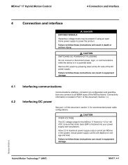
YUMPU automatically turns print PDFs into web optimized ePapers that Google loves.
<strong>MODBUS</strong>/<strong>TCP</strong><br />
<strong>Fieldbus</strong> <strong>manual</strong><br />
MDrive <strong>Motion</strong> Control<br />
Products
<strong>MODBUS</strong>/<strong>TCP</strong> Implementation and Reference<br />
Date Revision Changes<br />
09/14/2010 R091410 Initial Release<br />
10/27/2010 R102710 Added registers specifi c to MDrivePlus2 <strong>Motion</strong> Control<br />
02/01/11 R020111 Added instructions for upgrading the Ethernet controller fi rmware<br />
The information in IMS Schneider Electric <strong>Motion</strong> USA product documentation<br />
and on this web site has been carefully checked and is believed to<br />
be accurate; however, no responsibility is assumed for inaccuracies.<br />
IMS Schneider Electric <strong>Motion</strong> USA reserves the right to make changes<br />
without further notice to any products to improve reliability, function or<br />
design. IMS Schneider Electric <strong>Motion</strong> USA does not assume any liability<br />
arising out of the application or use of any product or circuit described;<br />
neither does it convey any license under its patent rights of others.<br />
IMS Schneider Electric <strong>Motion</strong> USA’s general policy does not recommend<br />
the use of its products in life support or aircraft applications wherein a<br />
failure or malfunction of the product may directly threaten life or injury. Per<br />
the terms and conditions of sales of IMS Schneider Electric <strong>Motion</strong> USA,<br />
the user of IMS Schneider Electric <strong>Motion</strong> USA products in life support or<br />
aircraft applications assumes all risks of such use and indemnifi es IMS<br />
Schneider Electric <strong>Motion</strong> USA against all damages. aircraft applications<br />
assumes all risks of such use and indemnifi es IMS Schneider Electric <strong>Motion</strong><br />
USA against all damages.<br />
<strong>MODBUS</strong>/<strong>TCP</strong> Implementation and Reference Revision R020111<br />
Copyright © Schneider Electric <strong>Motion</strong> USA, All Rights Reserved
Important information<br />
This <strong>manual</strong> is part of the product.<br />
Carefully read this <strong>manual</strong> and observe all instructions.<br />
Keep this <strong>manual</strong> for future reference.<br />
Hand this <strong>manual</strong> and all other pertinent product documentation over to all<br />
users of the product.<br />
Carefully read and observe all safety instructions and the chapter “Before you<br />
begin - safety information”.
This page intentionally left blank
Revision R020111<br />
<strong>MODBUS</strong>/<strong>TCP</strong> <strong>Fieldbus</strong> <strong>manual</strong> Table of Contents<br />
Table of Contents<br />
Important information .................................................................... 3<br />
1 Introduction ................................................................................ 1-1<br />
1.1 About this <strong>manual</strong> ............................................................1-1<br />
1.2 Supported devices & protocols ........................................1-1<br />
1.2.1 Supported devices .............................................1-1<br />
1.3 Documentation reference ................................................1-2<br />
1.4 Product software .............................................................1-2<br />
1.4.1 <strong>TCP</strong>/IP Confi guration Utility ...............................1-2<br />
2 Safety .......................................................................................... 2-1<br />
2.1 Qualifi cation of personnel ................................................2-1<br />
2.2 Intended Use ...................................................................2-1<br />
2.3 Hazard Categories ..........................................................2-2<br />
2.4 Basic information .............................................................2-3<br />
3 <strong>MODBUS</strong> Implementation ......................................................... 3-1<br />
3.1 <strong>MODBUS</strong> overview .........................................................3-1<br />
3.2 Message format ...............................................................3-2<br />
3.2.1 `ADU (application data unit) ...............................3-3<br />
4 Function codes .......................................................................... 4-1<br />
4.1 Device ID .........................................................................4-1<br />
4.1.1 Read device identifi cation – 43 / 14 (0x2B / 0x0E) ...<br />
4-1<br />
4.2 Public function codes ......................................................4-3<br />
4.2.1 Read digital inputs 02 (0x02) .............................4-3<br />
4.2.2 Read coils (digital outputs) – 01 (0x01) .............4-4<br />
4.2.3 Write single coil (digital output) – 05 (0x05) .......4-5<br />
4.2.4 Read holding registers – 03 (0x03) ....................4-6<br />
4.2.5 Write multiple registers – 16 (0x10) ...................4-7<br />
4.3 Manufacturer specifi c function codes ..............................4-8<br />
4.3.1 Manufacturer specifi c commands using 65 (0x41)<br />
and 66 (0x42) ................................................................4-8<br />
4.3.2 Read manufacturer specifi c – 65 (0x41) ..........4-11<br />
4.3.2 Write manufacturer specifi c – 66 (0x42) ..........4-12<br />
5 Register map .............................................................................. 5-1<br />
5.1 Hybrid specifi c registers ..................................................5-5<br />
6 <strong>TCP</strong>/IP Confi guration Utility ..................................................... 6-1<br />
6.1 Installation .......................................................................6-1<br />
6.2 Screen overview ..............................................................6-1<br />
6.3 Confi guration ...................................................................6-2<br />
6.4 Functional testing - <strong>MODBUS</strong> tab ...................................6-3<br />
6.4.1 Device ID sub-tab ..............................................6-3<br />
6.4.2 <strong>Motion</strong> sub-tab ...................................................6-3<br />
6.4.3 I/O sub-tab .........................................................6-4<br />
6.5 Manual tab .......................................................................6-5<br />
6.5.1 Using the Manual tab to write functions / data ....6-6<br />
6.5.2 Using the Manual tab to read functions / data ....6-7<br />
i
Revision R020111<br />
Table of Contents<br />
List of Figures<br />
List of Tables<br />
ii<br />
<strong>MODBUS</strong>/<strong>TCP</strong> <strong>Fieldbus</strong> <strong>manual</strong><br />
6.6 Upgrading the Ethernet controller fi rmware ........................ h<br />
6.6.1 To begin ................................................................. i<br />
6.6.2 Set the Tftpd Server IP .......................................... i<br />
6.6.3 Set the Ethernet upgrade fi le name ....................... i<br />
6.6.4 Enter upgrade mode .............................................. j<br />
6.6.5 Complete upgrade process .................................... j<br />
Figure 3.1: Example <strong>MODBUS</strong> network with MDrive products. .3-1<br />
Figure 3.2: Client-server model ..................................................3-2<br />
Figure 3.3: . Construction of an ethernet data packet for <strong>MODBUS</strong>/<br />
<strong>TCP</strong> 3-2<br />
Figure 3.4: <strong>MODBUS</strong>/<strong>TCP</strong> data packet construction .................3-3<br />
Figure 6.1 <strong>TCP</strong>/IP Confi guration Utility ......................................6-1<br />
Figure 6.2: Confi guration tab ......................................................6-2<br />
Figure 6.3 <strong>Motion</strong> sub-tab ..........................................................6-3<br />
Figure 6.4: I/O sub-tab ...............................................................6-4<br />
Figure 6.5: Manual entry tab ......................................................6-5<br />
Figure 6.6: Writing a function using the Manual tab ..................6-6<br />
Figure 6.7: Reading a function using the Manual tab.................6-7<br />
Figure 6.8: <strong>TCP</strong>/IP Confi g tab ....................................................6-8<br />
Figure 6.9: Setting the Tftpd Server IP .......................................6-9<br />
Figure 6.10: Setting the upgrade fi le name ................................6-9<br />
Figure 6.11: Firmware upgrading .............................................6-11<br />
Table 3.1: MBAP header ............................................................3-3<br />
Table 4.1: Supported function codes .........................................4-1
Revision R020111<br />
<strong>MODBUS</strong>/<strong>TCP</strong> <strong>Fieldbus</strong> <strong>manual</strong> 1 Introduction<br />
1 Introduction<br />
1.1 About this <strong>manual</strong><br />
1.2 Supported devices & protocols<br />
1.2.1 Supported devices<br />
This <strong>manual</strong> is for use with the <strong>MODBUS</strong>/<strong>TCP</strong> Ethernet based MDrive<br />
<strong>Motion</strong> Control products.<br />
This <strong>manual</strong> was developed from the perspective that you already have<br />
an understanding of the <strong>MODBUS</strong> protocol.<br />
For detailed technical information on the <strong>MODBUS</strong>/<strong>TCP</strong> specifi cation,<br />
please see http://www.modbus-ida.org.<br />
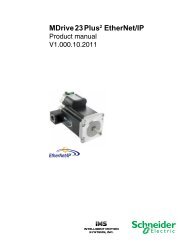
MDrive 23 Plus 2 <strong>Motion</strong> Control The MDrive 23 Plus <strong>Motion</strong> Control is supported absent the following:<br />
� I/O points 9 - 12<br />
All other features and functions are the same as the RS-422/485 versions.<br />
MDrive 23 Hybrid <strong>Motion</strong> Control The MDrive 23 Hybrid <strong>Motion</strong> Control is supported absent the following:<br />
� I/O points 9 - 12<br />
All other features and functions are the same as the RS-422/485 versions.<br />
Protocols The new MDrive <strong>Motion</strong> Control Ethernet products support two protocols<br />
in a single package:<br />
1) MCode/<strong>TCP</strong> — Schneider Electric <strong>Motion</strong> USA’s proprietary<br />
programming language for MDrive <strong>Motion</strong> Control products,<br />
adapted to utilize <strong>TCP</strong>/IP message formatting.<br />
If using the device using MCode/<strong>TCP</strong>, please see the MCode<br />
Programming and Reference Manual located on the web site at<br />
http://www.imshome.com/downloads/<strong>manual</strong>s.html.<br />
2) <strong>MODBUS</strong>/<strong>TCP</strong> — A standard open industrial protocol supported<br />
by a variety of machine components such as programmable<br />
controllers, drives and controls, I/O modules and switches.<br />
These protocols may be used separately or interchangeably, as is required<br />
by the constraints of the application by connecting to the port that<br />
the protocol is running on, 503 for MCode/<strong>TCP</strong> and 502 for <strong>MODBUS</strong>/<br />
<strong>TCP</strong>.<br />
First confi guration connection will need to be over MCode/<strong>TCP</strong> using<br />
the <strong>TCP</strong>/IP Confi guration Utility to change the IP address of the<br />
device. Information on MCode is found in the MCode Programming and<br />
Software Reference available on the website at http://www.schneiderelectric-motion.us.<br />
1-1
Revision R020111<br />
1 Introduction<br />
1.3 Documentation reference<br />
1.4 Product software<br />
1.4.1 <strong>TCP</strong>/IP Confi guration Utility<br />
1-2<br />
<strong>MODBUS</strong>/<strong>TCP</strong> <strong>Fieldbus</strong> <strong>manual</strong><br />
The following user’s <strong>manual</strong>s are available for the <strong>MODBUS</strong> devices:<br />
� Product hardware <strong>manual</strong>, describes the technical data and<br />
installation of the product.<br />
� Product software <strong>manual</strong>, describes the confi guration and programming<br />
of the product.<br />
� Quick Reference, describes the basic wiring, connection and<br />
use of this product. The quick reference is shipped in printed<br />
form with the product.<br />
This documentation is also available for download from our web site at:<br />
http://www.schneider-electric-motion.us.<br />
<strong>TCP</strong>/IP Confi guration Utility is a software tool for setting the IP, upgrading<br />
fi rmware and sending commands to the <strong>MODBUS</strong> device.<br />
This software is required for the initial setup of the device.<br />
Installation and usages instructions are to be found in Section 6 of this<br />
document.<br />
This software may be downloaded from the web site at:<br />
http://www.schneider-electric-motion.us.
Revision R020111<br />
<strong>MODBUS</strong>/<strong>TCP</strong> <strong>Fieldbus</strong> <strong>manual</strong> 2 Safety<br />
2 Safety<br />
2.1 Qualifi cation of personnel<br />
2.2 Intended Use<br />
Only appropriately trained persons who are familiar with and understand<br />
the contents of this <strong>manual</strong> and all other pertinent product<br />
documentation are authorized to work on and with this product.<br />
In addition, these persons must have received safety training to<br />
recognize and avoid hazards involved. These persons must have<br />
suffi cient technical training, knowledge and experience and be able<br />
to foresee and detect potential hazards that may be caused by using<br />
the product, by changing the settings and by the mechanical,<br />
electrical and electronic equipment of the entire system in which the<br />
product is used.<br />
All persons working on and with the product must be fully familiar<br />
with all applicable standards, directives, and accident prevention<br />
regulations when performing such work.<br />
The functions described in this <strong>manual</strong> are only intended for use with<br />
the basic product; you must read and understand the appropriate<br />
product <strong>manual</strong>.<br />
The product may only be used in compliance with all applicable<br />
safety regulations and directives, the specifi ed requirements and the<br />
technical data.<br />
Prior to using the product, you must perform a risk assessment in<br />
view of the planned application. Based on the results, the appropriate<br />
safety measures must be implemented.<br />
Since the product is used as a component in an entire system, you<br />
must ensure the safety of persons by means of the design of this<br />
entire system (for example, machine design).<br />
Operate the product only with the specifi ed cables and accessories.<br />
Use only genuine accessories and spare parts.<br />
Any use other than the use explicitly permitted is prohibited and can<br />
result in hazards.<br />
Electrical equipment should be installed, operated, serviced, and<br />
maintained only by qualifi ed personnel.<br />
The product must NEVER be operated in explosive atmospheres<br />
(hazardous locations, Ex areas).and spare parts.<br />
2-1
Revision R020111<br />
2 Safety<br />
2.3 Hazard Categories<br />
2-2<br />
<strong>MODBUS</strong>/<strong>TCP</strong> <strong>Fieldbus</strong> <strong>manual</strong><br />
Safety instructions to the user are highlighted by safety alert symbols<br />
in the <strong>manual</strong>. In addition, labels with symbols and/or instructions<br />
are attached to the product that alert you to potential hazards.<br />
Depending on the seriousness of the hazard, the safety instructions<br />
are divided into 4 hazard categories.<br />
DANGER indicates an imminently hazardous situation, which,<br />
if not avoided, will result in death or serious injury.<br />
WARNING indicates a potentially hazardous situation, which, if<br />
not avoided, can result in death, serious injury, or equipment<br />
damage.<br />
CAUTION indicates a potentially hazardous situation, which, if<br />
not avoided, can result in injury or equipment damage.<br />
CAUTION used without the safety alert symbol, is used to address<br />
practices not related to personal injury (e.g. can result in<br />
equipment damage).
Revision R020111<br />
<strong>MODBUS</strong>/<strong>TCP</strong> <strong>Fieldbus</strong> <strong>manual</strong> 2 Safety<br />
2.4 Basic information<br />
UNINTENDED CONSEQUENCES OF EQUIPMENT OPERATION<br />
When the system is started, the drives are usually out of the<br />
operator’s view and cannot be visually monitored.<br />
• Only start the system if there are no persons in the hazardous<br />
area.<br />
Failure to follow these instructions will result in death or<br />
serious injury.<br />
LOSS OF CONTROL<br />
• The designer of any control scheme must consider the<br />
potential failure modes of control paths and, for certain<br />
critical functions, provide a means to achieve a safe state<br />
during and after a path failure. Examples of critical control<br />
functions are emergency stop, overtravel stop, power outage<br />
and restart.<br />
• Separate or redundant control paths must be provided for<br />
critical functions.<br />
• System control paths may include communication links.<br />
Consideration must be given to the implication of unanticipated<br />
transmission delays or failures of the link.<br />
• Observe all accident prevention regulations and local<br />
safety guidelines. 1)<br />
• Each implementation of the product must be individually<br />
and thoroughly tested for proper operation before being<br />
placed into service.<br />
Failure to follow these instructions can result in death or<br />
serious injury.<br />
1) For USA: Additional information, refer to NEMA ICS 1.1 (latest edition), “Safety<br />
Guidelines for the Application, Installation, and Maintenance of Solid State Control”<br />
and to NEMA ICS 7.1 (latest edition), “Safety Standards for Construction and Guide<br />
for Selection, Installation and Operation of Adjustable-Speed Drive Systems”.<br />
HOT PLUGGING!<br />
Do not connect or disconnect power, logic, or communications<br />
while the device is in a powered state.<br />
Remove DC power by powering down at the AC side of the DC<br />
power supply.<br />
Failure to follow these instructions can result in equipment<br />
damage.<br />
2-3
Revision R020111<br />
2 Safety<br />
2-4<br />
This page has been intentionally left blank.<br />
<strong>MODBUS</strong>/<strong>TCP</strong> <strong>Fieldbus</strong> <strong>manual</strong>
Revision R020111<br />
<strong>MODBUS</strong>/<strong>TCP</strong> <strong>Fieldbus</strong> <strong>manual</strong> 3 <strong>MODBUS</strong>/<strong>TCP</strong><br />
3 <strong>MODBUS</strong> Implementation<br />
3.1 <strong>MODBUS</strong> overview<br />
<strong>MODBUS</strong> is a communications interface developed in 1979 by PLC<br />
manufacturer Modicon, Inc. (now a brand of Schneider Electric).<br />
<strong>MODBUS</strong> is designed for multidrop networks based on a master-client<br />
architecture.<br />
The availability of devices using <strong>MODBUS</strong> has made it a de facto<br />
standard for industrial communications network. <strong>MODBUS</strong> was originally<br />
developed for use with serial communications interfaces such as<br />
RS-232 and RS-485, <strong>MODBUS</strong>/<strong>TCP</strong> communications over <strong>TCP</strong>/IP has<br />
become a standard because of the ease of interface and simpler message<br />
format.<br />
Controller<br />
Ethernet switch<br />
MDrive #1<br />
e.g. 192.168.33.1<br />
PC<br />
Figure 3.1: Example <strong>MODBUS</strong> network with MDrive products.<br />
Additional Ethernet devices<br />
MDrive #2<br />
e.g. 192.168.33.2<br />
3-1
Revision R020111<br />
3 <strong>MODBUS</strong>/<strong>TCP</strong><br />
3.2 Message format<br />
3-2<br />
Ethernet header<br />
(Ethernet addresses)<br />
Layer 1: Physical layer<br />
<strong>MODBUS</strong>/<strong>TCP</strong> <strong>Fieldbus</strong> <strong>manual</strong><br />
<strong>MODBUS</strong>/<strong>TCP</strong> is basically the <strong>MODBUS</strong> serial RTU encapsulated in a<br />
<strong>TCP</strong>/IP wrapper and is used for <strong>TCP</strong>/IP communications between client<br />
and server devices on an Ethernet <strong>TCP</strong>/IP network.<br />
Client<br />
(PC, Controller)<br />
Request<br />
Figure 3.2: Client-server model<br />
Response<br />
Server<br />
(MDrive)<br />
<strong>MODBUS</strong>/<strong>TCP</strong> uses the OSI (Open Systems Interconnection) networking<br />
model. The <strong>MODBUS</strong> ADU (Application Data Unit) makes up the<br />
OSI application layer and is wrapped inside the data array of the <strong>TCP</strong>/<br />
IP Ethernet data packet. Figure 3.3 below shows the constructiopn of a<br />
<strong>TCP</strong>/IP Ethernet data packet used tor the <strong>MODBUS</strong>/<strong>TCP</strong> protocol.<br />
IP FRAME<br />
IP header<br />
(IP addresses)<br />
Layer 2: Ethernet (data link layer)<br />
<strong>TCP</strong> FRAME<br />
Layer 3: IP (network layer)<br />
<strong>TCP</strong> header<br />
(Port numbers)<br />
Layer 4: <strong>TCP</strong> (transport layer)<br />
Ethernet data array<br />
APPLICATION DATA UNIT<br />
MBAP header Protocol data unit<br />
Layer 5: ADU (application layer)<br />
IP data array<br />
Cable (copper, fiber, etc.)<br />
<strong>TCP</strong> data array<br />
Figure 3.3: Construction of an ethernet data packet for <strong>MODBUS</strong>/<strong>TCP</strong><br />
FCS<br />
(Checksum)
Revision R020111<br />
<strong>MODBUS</strong>/<strong>TCP</strong> <strong>Fieldbus</strong> <strong>manual</strong> 3 <strong>MODBUS</strong>/<strong>TCP</strong><br />
3.2.1 `ADU (application data unit)<br />
Transaction ID<br />
A <strong>MODBUS</strong>/<strong>TCP</strong> data packet, or Application Data Unit (ADU) consists<br />
of two components:<br />
1) <strong>MODBUS</strong> Application Protocol (MBAP) header<br />
2) Protocol Data Unit (PDU)<br />
The information contained in the ADU is embedded in the data portion<br />
of the <strong>TCP</strong> frame.<br />
Addressing and Checksum<br />
handled by the <strong>TCP</strong> frame<br />
Modbus Application Protocol (MBAP) Header<br />
Address Function code Data Checksum<br />
Function code and data<br />
not modified<br />
Protocol ID Length field Unit ID<br />
Application Data Unit (ADU)<br />
Traditional Modbus serial frame<br />
Function code Data<br />
Protocol Data Unit (PDU)<br />
Function code Data<br />
(2 bytes) (2 bytes) (2 bytes) (1 byte) (1 byte) (1 to 65535 bytes)<br />
<strong>TCP</strong>/IP Application Data Unit (ADU)<br />
This information is embedded in the data portion of the <strong>TCP</strong> frame<br />
Figure 3.4: <strong>MODBUS</strong>/<strong>TCP</strong> data packet construction<br />
MBAP header The MBAP header is 7 bytes long and consists of the following fi elds<br />
made up of four fi elds”<br />
Fields Length Description<br />
Transaction<br />
identifier<br />
2 bytes ID of a <strong>MODBUS</strong> request/response transaction.<br />
This field is used for transaction pairing, the<br />
server will copy in the Transaction ID of the<br />
request into the response.<br />
Protocol identifier 2 bytes 0 = <strong>MODBUS</strong> protocol<br />
Length 2 bytes Number of bytes following, including the Unit ID<br />
and the byte length of the PDU.<br />
Unit identifier 1 byte ID of a remote slave. Used for intra-system<br />
communications with other buses i.e. between<br />
<strong>MODBUS</strong>/<strong>TCP</strong> and a <strong>MODBUS</strong> serial line slave<br />
through a gateway.<br />
Table 3.1 MBAP header<br />
3-3
Revision R020111<br />
3 <strong>MODBUS</strong>/<strong>TCP</strong><br />
3-4<br />
Protocol Data Unit (PDU) The PDU consists of 2 parts:<br />
<strong>MODBUS</strong>/<strong>TCP</strong> <strong>Fieldbus</strong> <strong>manual</strong><br />
1) Function code: the function code identifi es the action to be<br />
taken using the data bytes that will follow. These functions are<br />
covered in detail in Section 4 of this document. Basic functions<br />
are:<br />
Reading inputs, writing coils (digital outputs), read/write registers<br />
and manufacturer specifi c confi guration functions.<br />
2) Data: The data contained in the PDU, it will consist of the data<br />
and/or parameters associated with the commands to operate<br />
your MDrive product.
Revision R020111<br />
<strong>MODBUS</strong>/<strong>TCP</strong> <strong>Fieldbus</strong> <strong>manual</strong> 4 Function codes<br />
4 Function codes<br />
4.1 Device ID<br />
The MDrive supports the following function codes:<br />
Function code<br />
dec<br />
Device ID<br />
hex<br />
Description<br />
43/14<br />
Public<br />
0x2B/0x0E Read device identification<br />
02 0x02 Read digital inputs<br />
01 0x01 Read coils (digital outputs)<br />
05 0x05 Write single coil (digital output)<br />
03 0x03 Read holding register<br />
16 0x10 Write multiple registers<br />
Manufacturer specific<br />
65 0x41 Read I/O and trip configuration and parameters<br />
66 0x42 Write I/O and trip configuration and parameters, enter<br />
upgrade mode.<br />
Table 4.1: Supported function codes<br />
Exception codes Each function has 4 error, or exception codes that will return in case of<br />
an error with the transaction. They are:<br />
01 – Illegal or not supported function<br />
02 – Illegal data address<br />
03 – Illegal data value<br />
04 – Slave device failure<br />
4.1.1 Read device identifi cation – 43 / 14 (0x2B / 0x0E)<br />
The device type contains information about your MDrive product, importantly<br />
the part number, serial number, and fi rmware version installed.<br />
Request Length Value<br />
Function code 1 byte 0x2B<br />
MEI* type 1 byte 0x0E<br />
Read device ID code 1 byte 01 / 02 / 03 / 04<br />
Object ID 1 byte 0x00 – 0x06<br />
*<strong>MODBUS</strong> Encapsulated Interface<br />
4-1
Revision R020111<br />
4 Function codes<br />
4-2<br />
<strong>MODBUS</strong>/<strong>TCP</strong> <strong>Fieldbus</strong> <strong>manual</strong><br />
Response Length Value<br />
Function code 1 byte 0x2B<br />
MEI type 1 byte 0x0E<br />
Read device ID code 1 byte<br />
Conformity level 1 byte<br />
More follows 1 byte<br />
NextObjectId 1 byte 0x00<br />
Number Of Obects 1 byte 0x06<br />
Object Id 1 byte 0x00<br />
Object Length 1 byte 0x03<br />
Object Value 3 bytes “SEM USA”<br />
Object Id 1 byte 0x01<br />
Object Length 1 byte 0xXX<br />
Object Value X bytes “MDrive P/N”<br />
Object Id 1 byte 0x02<br />
Object Length 1 byte 0x08<br />
Object Value 8 bytes “4.0.0.0”<br />
Object Id 1 byte 0x03<br />
Object Length 1 byte 0x20<br />
Object Value 32 bytes “www.imshome.com”<br />
Object Id 1 byte 0x04<br />
Object Length 1 byte 0x0A<br />
Object Value 10 bytes MDrive Ethernet<br />
Object Id 1 byte 0x05<br />
Object Length 1 byte 0xXX<br />
Object Value X bytes “Serial number”<br />
Object Id 1 byte 0x06<br />
Object Length 1 byte 0x0C<br />
Object Value 12 bytes ASI 4.x.x.x
Revision R020111<br />
<strong>MODBUS</strong>/<strong>TCP</strong> <strong>Fieldbus</strong> <strong>manual</strong> 4 Function codes<br />
4.2 Public function codes<br />
4.2.1 Read digital inputs 02 (0x02)<br />
Function 02 is used to read the state of the digital inputs 1 - 4 on your<br />
MDrive product. The request PDU contains the starting address of the<br />
fi rst input specifi ed, and the number of inputs.<br />
In the response message the input states are packaged as 1 input per<br />
bit of the data fi eld where status is indicated as 1 = ON and 0 = OFF.<br />
The LSB of the data byte will be the address of the input in the request.<br />
NOTE: Digital inputs on the MDrive may also be read using the holding<br />
registers.<br />
NOTE 2: The inputs must be confi gured as such using the manufacturer<br />
specifi c function code 66 (0x42).<br />
Request Length Value<br />
Function code 1 byte 0x02<br />
Starting Address 2 bytes 0x002D – 0x0030<br />
Quantity of inputs 1 byte 1 to 4<br />
Response Length Value<br />
Function code 1 byte 0x02<br />
Byte Count 1 byte 1 to 4<br />
Input status 1 to 4 bytes<br />
Error Length Value<br />
Error code 1 byte 0x82<br />
Exception 1 byte 01, 02, 03 or 04<br />
Input status 1 to 4 bytes<br />
Example Example shows a read of all 4 MDrive digital inputs, the response shows<br />
input states: I1=1, I2=1, I3=0, I4=1. Input 1 is the input address and is<br />
therefore the LSB,<br />
Request Response<br />
Function 0x02 Function 0x02<br />
Starting address Hi 0x00 Byte count 0x01<br />
Starting address Lo 0x2D Input status 4 – 1 0x0B<br />
Qty of inputs Hi 0x00<br />
Qty of inputs Lo 0x04<br />
4-3
Revision R020111<br />
4 Function codes<br />
4.2.2 Read coils (digital outputs) – 01 (0x01)<br />
4-4<br />
<strong>MODBUS</strong>/<strong>TCP</strong> <strong>Fieldbus</strong> <strong>manual</strong><br />
Function 01 is used to read the state of the digital outputs 1 - 4 on your<br />
MDrive product. The request PDU contains the starting address of the<br />
fi rst output specifi ed, and the number of outputs.<br />
In the response message the output states are packaged as 1 output<br />
per bit of the data fi eld where status is indicated as 1 = ON and 0 =<br />
OFF. The LSB of the data byte will be the output of the address in the<br />
request.<br />
NOTE: Digital outputs on the MDrive may also be read using the holding<br />
registers.<br />
NOTE 2: The outputs must be confi gured as such using the manufacturer<br />
specifi c function code 66 (0x42).<br />
Request Length Value<br />
Function code 1 byte 0x01<br />
Starting Address 2 bytes 0x004B – 0x004E<br />
Quantity of outputs 1 byte 1 to 4<br />
Response Length Value<br />
Function code 1 byte 0x01<br />
Byte Count 1 byte 1 to 4<br />
Input status 1 to 4 bytes<br />
Error Length Value<br />
Error code 1 byte 0x81<br />
Exception 1 byte 01, 02, 03 or 04<br />
Input status 1 to 4 bytes<br />
Example Example shows a read of all 4 MDrive digital outputs, the response<br />
shows outputs states:O1=1, O2=0, O3=1, O4=0. Output 1 is the output<br />
address and is therefore the LSB,<br />
Request Response<br />
Function 0x01 Function 0x02<br />
Starting address Hi 0x00 Byte count 0x01<br />
Starting address Lo 0x4B Output status 4 – 1 0x05<br />
Qty of outputs Hi 0x00<br />
Qty of outputs Lo 0x04
Revision R020111<br />
<strong>MODBUS</strong>/<strong>TCP</strong> <strong>Fieldbus</strong> <strong>manual</strong> 4 Function codes<br />
4.2.3 Write single coil (digital output) – 05 (0x05)<br />
This function is used to turn a single output point ON or OFF.<br />
The state is specifi ed by a constant in the request data fi eld:<br />
� 0xFF00 – turns the output ON<br />
� 0x0000 – turns the output OFF<br />
All other values are illegal and will return an exception code 03: Illegal<br />
data value.<br />
NOTE: Digital outputs on the MDrive may also be written using the<br />
holding registers.<br />
NOTE 2: The outputs must be confi gured as such using the manufacturer<br />
specifi c function code 66 (0x42).<br />
Request Length Value<br />
Function code 1 byte 0x05<br />
Output address 2 bytes 0x004B – 0x004E<br />
Output value 2 bytes 0x0000 or 0xFF00<br />
Response Length Value<br />
Function code 1 byte 0x05<br />
Output address 2 bytes 0x004B – 0x004E<br />
Output value 2 bytes 0x0000 or 0xFF00<br />
Error Length Value<br />
Error code 1 byte 0x85<br />
Exception 1 byte 01, 02, 03 or 04<br />
Example Example shows setting output 3 to an ON state.<br />
Request Response<br />
Function 0x05 Function 0x05<br />
Output address Hi 0x00 Output address Hi 0x00<br />
Output address Lo 0x4D Output address Lo 0x4D<br />
Output value Hi 0xFF Output value Hi 0xFF<br />
Output value Lo 0x00 Output value Lo 0x00<br />
4-5
Revision R020111<br />
4 Function codes<br />
4.2.4 Read holding registers – 03 (0x03)<br />
4-6<br />
<strong>MODBUS</strong>/<strong>TCP</strong> <strong>Fieldbus</strong> <strong>manual</strong><br />
Tis function code is used to read a contingous block of holding registers<br />
in your MDrive. The request PDU specifi es the starting register address<br />
and the number of registers.<br />
MDrive command data mapped to the holding registers measure 1, 2<br />
or 4 bytes in length, therefore you will not need to read more than two<br />
consecutive registers per request.<br />
NOTE: A number of registers are marked as reserved. Use of any of<br />
these registers will return a exception code 02: illegal data address.<br />
See Section 5 of this document for the register map.<br />
Request Length Value<br />
Function code 1 byte 0x03<br />
Starting address 2 bytes 0x0000 – 0x00A7*<br />
Qty of addresses 2 bytes 1 to 4<br />
*A number of addresses in this block are reserved for future use and<br />
will return an error.<br />
Response Length Value<br />
Function code 1 byte 0x03<br />
Byte count 2 bytes 1 – 4<br />
Register value 2 bytes 0x00 to 0x04<br />
Error Length Value<br />
Error code 1 byte 0x83<br />
Exception 1 byte 01, 02, 03 or 04<br />
Example Example shows reading registers 0x008A and 0x008B (maximum<br />
velocity). The value reads as 0x00 0B B8 00 or decimal 768000 steps/<br />
second.<br />
Request Response<br />
Function 0x0F Function 0x0F<br />
Starting address Hi 0x00 Byte count 0x04<br />
Starting address Lo 0x8A Register value Hi 0x00<br />
Qty of registers Hi 0x00 Register value Lo 0x0B<br />
Qty of registers Lo 0x02 Register value Hi 0xB8<br />
Register value Lo 0x00
Revision R020111<br />
<strong>MODBUS</strong>/<strong>TCP</strong> <strong>Fieldbus</strong> <strong>manual</strong> 4 Function codes<br />
4.2.5 Write multiple registers – 16 (0x10)<br />
Tis function code is used to write a contingous block of registers in your<br />
MDrive. The request PDU specifi es the starting register address and<br />
the number of registers teo be written.<br />
MDrive command data mapped to the registers measure 1, 2 or 4 bytes<br />
in length, therefore you will not need to write more than two consecutive<br />
registers per request.<br />
NOTE: A number of registers are marked as reserved. Use of any of<br />
these registers will return a exception code 02: illegal data address.<br />
See Section 5 of this document for the register map.<br />
Request Length Value<br />
Function code 1 byte 0x10<br />
Starting address 2 bytes 0x0000 – 0x00A7*<br />
Qty of addresses 2 bytes 1 to 4<br />
Byte count 1 byte 2 to 4<br />
Registers value to 4 bytes value<br />
*A number of addresses in this block are reserved for future use and<br />
will return an error.<br />
Response Length Value<br />
Function code 1 byte 0x10<br />
Byte count 2 bytes 1 – 4<br />
Register value 2 bytes 0x00 to 0x04<br />
Error Length Value<br />
Error code 1 byte 0x90<br />
Exception 1 byte 01, 02, 03 or 04<br />
Example Example shows writing registers 0x008A and 0x008B (maximum velocity).<br />
The value will be set as decimal 600000 steps/second, or 0x00 09<br />
27 C0.<br />
Request Response<br />
Function 0x10 Function 0x10<br />
Starting address Hi 0x00 Starting address Hi 0x00<br />
Starting address Lo 0x8A Starting address Lo 0x8A<br />
Qty of registers Hi 0x00 Qty of registers Hi 0x00<br />
Qty of registers Lo 0x02 Qty of register s Lo 0x02<br />
Byte count 0x04 Byte count 0x04<br />
Registers value Hi 0x00<br />
Registers value Lo 0x09<br />
Registers value Hi 0x27<br />
Registers value Lo 0xC0<br />
4-7
Revision R020111<br />
4 Function codes<br />
4.3 Manufacturer specifi c function codes<br />
4-8<br />
<strong>MODBUS</strong>/<strong>TCP</strong> <strong>Fieldbus</strong> <strong>manual</strong><br />
The device supports two manufacturer specifi c function codes for confi<br />
guring:<br />
� I/O points 1 - 4<br />
� I/O point 7 - 8 (Clock I/O)<br />
� Clock Ratio<br />
� Analog input<br />
� Capture input/trip output<br />
� Trip on relative position<br />
� Upgrading fi rmware<br />
These are:<br />
� 65 (0x41) – Read specifi c functions<br />
� 66 (0x42) – Write specifi c functions<br />
4.3.1 Manufacturer specifi c commands using 65 (0x41) and 66 (0x42)<br />
General purpose I/O setup The ASCII of the command mnemonic is sent in revers order in the request PDU i.e.<br />
1S, 2S etc. The parameter string is written or read in normal sequence.<br />
MCode mnemonic S1 (I/O 1) S2 (I/O 2) S3 (I/O 3) S4 (I/O 4)<br />
Mnemonic<br />
Hi word<br />
Lo word<br />
0x20 0x20<br />
0x31 0x53<br />
0x20 0x20<br />
0x32 0x53<br />
0x20 0x20<br />
0x33 0x53<br />
0x20 0x20<br />
0x34 0x53<br />
Parameter data length 6 – 7 bytes<br />
Parameter<br />
string<br />
example<br />
Params<br />
ASCII<br />
Hex<br />
=<br />
3D<br />
A<br />
0<br />
30<br />
,<br />
2C<br />
B<br />
0<br />
30<br />
,<br />
2C<br />
C<br />
0<br />
30<br />
See parameters table<br />
below for details<br />
Parameters<br />
A – I/O type<br />
Input functions<br />
B – Active Hi/Lo C – Sinking or Sourcing<br />
dec hex function dec hex dec hex<br />
0 30 General purpose 0 30 Active Lo 0 30 Sinking<br />
1 31 Homing 1 31 Active Hi 1 31 Sourcing<br />
2 32 Limit +<br />
3 33 Limit –<br />
5 35 Soft stop<br />
7 37 Jog +<br />
8 38 Jog –<br />
11 31 31 Reset<br />
Output Functions<br />
16 31 36 General purpose<br />
17 31 37 Moving<br />
18 31 38 Fault<br />
20 32 30 Velocity changing<br />
21 32 31 Locked rotor<br />
23 32 33 Moving to position<br />
24 32 34 Hybrid circuitry active<br />
25 32 35 Make-up active
Revision R020111<br />
<strong>MODBUS</strong>/<strong>TCP</strong> <strong>Fieldbus</strong> <strong>manual</strong> 4 Function codes<br />
Clock I/O setup (I/O 7 & 8) The ASCII of the command mnemonic is sent in revers order in the request PDU i.e.<br />
1S, 2S etc. The parameter string is written or read in normal sequence.<br />
MCode mnemonic S7 (I/O 7) S8 (I/O 8)<br />
Mnemonic<br />
Hi word<br />
Lo word<br />
0x20 0x20<br />
0x37 0x53<br />
0x20 0x20<br />
0x38 0x53<br />
Parameter data length 4 – 5 bytes<br />
Parameter<br />
string<br />
example<br />
Params<br />
ASCII<br />
Hex<br />
=<br />
3D<br />
A<br />
34<br />
33 34<br />
,<br />
2C<br />
B<br />
1<br />
31<br />
See parameters table below for<br />
details<br />
Parameters<br />
A – I/O type<br />
Input functions<br />
B – Active Hi/Lo<br />
dec hex function dec hex<br />
33 33 33 Step / direction 0 30 Active Lo<br />
34 33 34 Quadrature 1 31 Active Hi<br />
35 33 35 Up / down<br />
Output Functions<br />
49 34 39 Step / direction<br />
50 35 30 Quadrature<br />
51 35 31 Up / down<br />
Set clock ratio The ASCII of the command mnemonic is sent in revers order in the request PDU i.e.<br />
RC. The parameter string is written or read in normal sequence.<br />
Clock Ratio value for electronic gearing. The value selected will set the ratio from the<br />
clock input on I/O 7 (Step Clock) and I/O 8<br />
MCode mnemonic CR (Clock Ratio)<br />
Mnemonic<br />
Hi word<br />
Lo word<br />
0x20 0x20<br />
0x52 0x43<br />
Parameter data length Up to 6 bytes<br />
ASCII = 1 . 5 0 0<br />
Hex 3D 31 2E 35 30 30<br />
4-9
Revision R020111<br />
4 Function codes<br />
4-10<br />
<strong>MODBUS</strong>/<strong>TCP</strong> <strong>Fieldbus</strong> <strong>manual</strong><br />
Analog input setup The ASCII of the command mnemonic is sent in revers order in the request PDU i.e.<br />
5S. The parameter string is written or read in normal sequence.<br />
The analog input may be configured for voltage or current mode with ranges of 0 to 5<br />
VDC, 0 to 10 VDC, o to 20 mA or 4 to 20 mA.<br />
Capture/trip I/O setup<br />
MCode mnemonic S5 (Analog Input)<br />
Mnemonic<br />
Hi word<br />
Lo word<br />
0x20 0x20<br />
0x35 0x53<br />
Parameter data length 4 – 5 bytes<br />
Parameter<br />
string<br />
example<br />
Params<br />
ASCII<br />
Hex<br />
=<br />
3D<br />
A<br />
0<br />
30<br />
,<br />
2C<br />
B<br />
0<br />
30<br />
See parameters table<br />
below for details<br />
Parameters<br />
A – Input mode B – Input range<br />
dec hex mode dec hex range<br />
9 39 Voltage<br />
0<br />
1<br />
30<br />
31<br />
0 – 5 VDC<br />
0 – 10 VDC<br />
10 31 30 Current<br />
0<br />
1<br />
30<br />
31<br />
0 – 20 mA<br />
4 – 20 mA<br />
The ASCII of the command mnemonic is sent in revers order in the request PDU i.e.<br />
31S. The parameter string is written or read in normal sequence.<br />
Note the the only trip function available is trip on relative position.<br />
MCode mnemonic S13 (Capture output/trip input)<br />
Mnemonic<br />
Hi word<br />
Lo word<br />
0x20 0x33<br />
0x31 0x53<br />
Parameter data length 4 – 5 bytes<br />
Parameter<br />
string<br />
example<br />
Params<br />
ASCII<br />
Hex<br />
=<br />
3D<br />
A<br />
60<br />
30<br />
,<br />
2C<br />
B<br />
0<br />
30<br />
See parameters table<br />
below for details<br />
Parameters<br />
A – Input mode B – Active state<br />
dec hex mode dec hex range<br />
60 36 30 Capture input 0 30 Active Lo<br />
61 36 31 Trip output 1 31 Active Hi
Revision R020111<br />
<strong>MODBUS</strong>/<strong>TCP</strong> <strong>Fieldbus</strong> <strong>manual</strong> 4 Function codes<br />
Trip on relative position The ASCII of the command mnemonic is sent in revers order in the request PDU i.e.<br />
RT. The parameter string is written or read in normal sequence.<br />
Note the the only trip function available is trip on relative position. to re-enable the trip,<br />
use register 0x007D.<br />
4.3.2 Read manufacturer specifi c – 65 (0x41)<br />
MCode mnemonic TR (Trip on relative position)<br />
Mnemonic<br />
Hi word<br />
Lo word<br />
0x20 0x20<br />
0x52 0x54<br />
Parameter data length Up to 11 bytes<br />
ASCII = 6 5 0 0 0<br />
Hex 3D 36 35 30 30 30<br />
Request Length Value<br />
Function code 1 byte 0x41<br />
Mnemonic Hi word 2 bytes 0x2020 0x2020/2033*<br />
Mnemonic Lo word 2 bytes See section 4.3.1 for listing<br />
*For capture/trip I/O point.<br />
Response Length Value<br />
Function code 1 byte 0x41<br />
Byte count 2 bytes N* (quantity of characters returned)<br />
Response n bytes n=N or N+1<br />
Error Length Value<br />
Error code 1 byte 0xC1<br />
Exception 1 byte 01, 02, 03 or 04<br />
Example Example shows reading the setting of the trip on relative input (TR). The<br />
value reads as 0x35 31 32 30 30 30 or decimal 512000 steps.<br />
Request Response<br />
Function 0x41 Function 0x41<br />
Mnemonic Hi word<br />
Mnemonic Lo word<br />
0x00<br />
0x35<br />
0x00 0x31<br />
0x52<br />
0x54<br />
Response<br />
0x32<br />
0x30<br />
0x30<br />
0x30<br />
4-11
Revision R020111<br />
4 Function codes<br />
4.3.2 Write manufacturer specifi c – 66 (0x42)<br />
4-12<br />
<strong>MODBUS</strong>/<strong>TCP</strong> <strong>Fieldbus</strong> <strong>manual</strong><br />
Request Length Value<br />
Function code 1 byte 0x42<br />
Mnemonic Hi word 2 bytes 0x2020 0x2020/2033*<br />
Mnemonic Lo word 2 bytes See section 4.3.1 for listing<br />
Byte count 1 byte 1-n bytes (28 max)<br />
Parameter data string n bytes See section 4.3.1 for listing<br />
*For capture/trip I/O point.<br />
Response Length Value<br />
Function code 1 byte 0x42<br />
Byte count written 1 bytes N* (quantity of characters returned)<br />
Mnemonic Hi word 2 bytes 0x2020 0x2020/2033*<br />
Mnemonic Lo word 2 bytes See section 4.3.1 for listing<br />
Error Length Value<br />
Error code 1 byte 0xC2<br />
Exception 1 byte 01, 02, 03 or 04<br />
Example Example shows setting input 1 (S1). The input is shown set to a general<br />
purpose sinking input which is active when Hi, or S1=0,1,0. Not that the<br />
data string includes all of the characters, including the equal sign and<br />
the commas.<br />
Request Response<br />
Function 0x41 Function 0x41<br />
Mnemonic Hi word<br />
Mnemonic Lo word<br />
Parameter data<br />
string<br />
0x00 Bytes written 0x06<br />
0x00<br />
0x52<br />
Mnemonic Hi word<br />
0x00<br />
0x00<br />
0x54<br />
0x3D<br />
0x30<br />
0x2C<br />
0x31<br />
0x2C<br />
0x30<br />
Mnemonic Lo word<br />
0x52<br />
0x54
Revision R020111<br />
<strong>MODBUS</strong>/<strong>TCP</strong> <strong>Fieldbus</strong> <strong>manual</strong> 5 Register Map<br />
5 Register map<br />
Function Address Bytes Description Range Default MCode<br />
Acceleration 0x0000 -<br />
0x0001<br />
4 Sets the acceleration rate in steps per second2 . 91 to 1525878997 1000000 A<br />
Reserved 0x0002-4 — Reserved — — —<br />
Counter 1 0x0005 - 4 Variable contains the count of clock pulses -2147483648 to 0 C1<br />
0x0006<br />
generated by the device.<br />
+2147483647<br />
Counter 2 0x0007 - 4 Variable contains the count of encoder counts -2147483648 to 0 C2<br />
0x0008<br />
read by the device.<br />
+2147483647<br />
Software reset 0x0009 1 Flag configures the device to respond (1) or not 0/1 1 CE<br />
enable<br />
respond (0) to a CTRL+C software reset.<br />
Reserved 0x000A — Reserved — — —<br />
Clock mode enable 1 0x000B 1 Flag to enable (1) or disable (0) clock mode<br />
(MDrivePlus only)<br />
0/1 0 CM<br />
Reserved 0x000C-E — Reserved — — —<br />
Input 1 debounce 0x000F 1 Sets digital filtering in milliseconds. Input must 0 – 255 0 D1<br />
Input 2 debounce<br />
Input 3 debounce<br />
0x0010<br />
0x0011<br />
be stable for the set time before state change is<br />
detected.<br />
D2<br />
D3<br />
Input 4 debounce 0x0012 D4<br />
Analog input filter 0x0013 1 Filter does continuos average by computing:<br />
(((X-1)/X)*current reading) + (1 / X) If X = 10,<br />
then: ((current averaged value * 9)/10) + (new<br />
reading / 10) == NEW current averaged value.<br />
0 – 255 0 D5<br />
Reserved 0x0014-17 — Reserved — — —<br />
Deceleration 0x0018 -<br />
0x0019<br />
4 Sets deceleration rate in steps per second2 . 91 – 1525878997 1000000 D<br />
Deadband 1 0x001A 2 Encoder deadband (MDrivePlus only) 0 to ±65000 10 DB<br />
Decrement variable 0x001B 1 instruction will decrement the specified variable<br />
by one.<br />
— — DC<br />
Drive enable 0x001C 1 Flag enables (1) or disables (0) the drive portion<br />
of the device.<br />
0/1 1 DE<br />
Reserved 0x001D — Reserved — — —<br />
Encode enable 0x001E 1 Enable encoder functions 0/1 0 EE<br />
Error flag 0x001F 1 Flag indicates whether an error condition exists<br />
(1) or not (0).<br />
0/1 0 EF<br />
Reserved 0x0020 — Reserved — — —<br />
Error 0x0021 2 Variable holds the error code of the last error.<br />
must be read or set to 0 to clear.<br />
— 0 ER<br />
Reserved 0x0022-28 — Reserved — — —<br />
Holding current 0x0029 1 Sets the motor holding current in percent (%) 0 to 100 5 HC<br />
Reserved 0x002A — Reserved — — —<br />
1 = MDrivePlus <strong>Motion</strong> Control version only<br />
5-1
Revision R020111<br />
5 Register Map<br />
5-2<br />
<strong>MODBUS</strong>/<strong>TCP</strong> <strong>Fieldbus</strong> <strong>manual</strong><br />
Function Address Bytes Description Range Default MCode<br />
Homing mode 0x002B 1 Sets the behavior of the axis for homing<br />
routines:<br />
Mode=1 - Slew – at VM, creep + at VI<br />
Mode=2 - Slew – at VM, creep – at VI<br />
Mode=3 - Slew + at VM, creep – at VI.<br />
Mode=4 - Slew + at VM, creep + at VI<br />
1 – 4 HM<br />
Hold current delay<br />
time<br />
0x002C 2 Set the time in milliseconds between the<br />
cessation of motion and shift to holding current<br />
percent. Total time is represented by the sum of<br />
0x002C+0x0049 (motor settling delay time. The<br />
sum cannot be more than 65535 msec.<br />
0 (no delay) or 2 –<br />
65535<br />
500 HT<br />
Read input 1 0x002D 1 Read the logic state of the specified input. 0/1 — I1<br />
Read input 2 0x002E I2<br />
Read input 3 0x002F I3<br />
Read input 4 0x0030 I4<br />
Read analog input 0x0031 Read the value of the analog input in counts. 0 – 1023 — I5<br />
Read index mark 1 0.0032 1 This variable will read the on/off state of the<br />
Encoder Index Mark (MDrivePlus only)<br />
0/1 — I6<br />
Reserved 0x0033-36 — Reserved — — —<br />
Increment variable 0x0037 1 Increments the specified variable by one. — — IC<br />
Reserved 0x0038-39 — Reserved — — —<br />
Read inputs 1 - 4 as 0x003A 1 Reads the logic states of inputs 1-4 and returns 0 – 15 — IL<br />
BCD<br />
them as a decimal value. Input 1 will represent<br />
the LSb..<br />
Read all inputs as<br />
BCD<br />
0x003B 1 Reads the logic states of inputs 1-4 and returns<br />
them as a decimal value. Input 1 will represent<br />
the LSb..<br />
0 – 15 — IN<br />
Reserved 0x003C-3E — Reserved — — —<br />
Jog enable 0x003F 1 Enables (1)/disables(0) jog functions when<br />
inputs are configured as Jog+ and Jog –.<br />
0/1 0 JE<br />
Reserved 0x0040-41 — Reserved — — —<br />
Limit stop mode 0x0042 1 Sets the behavior of the axis upon reaching a<br />
limit switch.<br />
Mode=1 – Normal limit function with decel ramp.<br />
Mode=2 – Stops motion with decel ramp, no<br />
homing.<br />
Mode=3 – Stops motion with decel ramp, stops<br />
program.<br />
Mode=4 – Normal limit function, no decel.<br />
Mode=5 – Stops motion, no decel, no homing.<br />
Mode=6 – Stops motion, stops program, no<br />
decel.<br />
1 – 6 1 LM<br />
Move to absolute<br />
position<br />
0x0043 -<br />
0x0044<br />
4 Point-to-point move to a ± absolute position. — — MA<br />
Moving to position 0x0045 1 Indicates that the axis is moving (1) to an<br />
absolute or relative position or stopped (0).<br />
Move to relative<br />
position<br />
0x0046 -<br />
0x0047<br />
1 = MDrivePlus <strong>Motion</strong> Control version only<br />
4 Point-to-point move to a ± position relative distance<br />
from current position.<br />
0/1 0 MP<br />
— — MR
Revision R020111<br />
<strong>MODBUS</strong>/<strong>TCP</strong> <strong>Fieldbus</strong> <strong>manual</strong> 5 Register Map<br />
Function Address Bytes Description Range Default MCode<br />
Microstep resolution 0x0048 1 Set the microstep resolution in microsteps per<br />
motor full step.<br />
See table 256 MS<br />
Motor settling delay<br />
time<br />
Available Microsteps Per Revolution<br />
0x0048= 1 2 4 5 8 10 16 25 32 50<br />
steps/rev 200 400 800 1000 1600 2000 3200 5000 6400 10000<br />
0x0048= 64 100 125 128 200 250 256 180 108 127<br />
steps/rev 12800 20000 25000 25600 40000 50000 51200 360001 216002 254003 1=0.01 deg/μstep 2=1 arc minute/μstep 3=0.001 mm/μstep<br />
0x0049 2 Specifies the motor settling delay time in<br />
milliseconds. This allows the motor to settle<br />
following a move. This variable is added to<br />
0x002C to determine the total time before<br />
shifting to holding current. The sum cannot be<br />
more than 65535 msec.<br />
0 – 65000 0 MT<br />
Moving 0x004A 1 Indicates whether the axis is in motion (1) or<br />
stationary (0).<br />
0/1 0 MV<br />
Write output 1 0x004B 1 Write (set) the logic state of the specified output. 0/1 — O1<br />
Write output 2 0x004C O2<br />
Write output 3 0x004D O3<br />
Write output 4 0x004E O4<br />
Reserved 0x004F-54 — Reserved — — —<br />
Set outputs 1 - 4 as a<br />
group<br />
Set outputs 1 - 4 as a<br />
group<br />
Position counter 0x0057 -<br />
0x0058<br />
Position capture at<br />
trip<br />
0x0055 1 Set outputs 1-4 as one 4 bit binary value. The<br />
value is entered in decimal, with a range of 0-15<br />
in binary where output 1 will be the LSb<br />
0x0056 1 Set outputs 1-4 as one 4 bit binary value. The<br />
value is entered in decimal, with a range of 0-15<br />
in binary where output 1 will be the LSb<br />
0x0059 -<br />
0x005A<br />
4 Sets or reads the axis ± position in motor steps.<br />
The value of the register will be used as the<br />
reference point for absolute and relative moves.<br />
4 Captures axis position during a trip event.<br />
Activation will occur upon any trip function<br />
EXCEPT a position trip.<br />
0 – 15 — OL<br />
0 – 15 — OT<br />
-2147483648 –<br />
+2147483647<br />
0 P<br />
— — PC<br />
Reserved 0x005B — Reserved — — —<br />
Position<br />
maintenance 1<br />
0x005C 1 Enables (1) or disables (0) position maintenance<br />
functions (MDrivePlus only)<br />
0/1 0 PM<br />
Reserved 0x005D-5E — Reserved — — —<br />
User register 1 0x005F -<br />
0x0060<br />
User register 2 0x0061 -<br />
0x0062<br />
User register 3 0x0063 -<br />
0x0064<br />
User register 4 0x0065 -<br />
0x0066<br />
4 registers may contain up to 11 digits including<br />
the sign and may be used to store and retrieve<br />
data.<br />
32 bit — R1<br />
Run current 0x0067 1 Sets the motor run current in percent (%). 1 to 100 25 RC<br />
Reserved 0x0068-75 — Reserved — — —<br />
1 = MDrivePlus <strong>Motion</strong> Control version only<br />
R2<br />
R3<br />
R4<br />
5-3
Revision R020111<br />
5 Register Map<br />
5-4<br />
<strong>MODBUS</strong>/<strong>TCP</strong> <strong>Fieldbus</strong> <strong>manual</strong><br />
Function Address Bytes Description Range Default MCode<br />
Save 0x0076 1 Saves variables and flags in working memory to<br />
NVM.<br />
— S<br />
Stall factor 1 0x0077 2 Difference between commanded position and<br />
encoder counts at which a stall is indicated<br />
(MDrivePlus only).<br />
0 to 65000 15 SF<br />
Slew axis 0x0078 -<br />
0x0079<br />
4 Slews the axis at velocity in steps/second<br />
in the specified ± direction, Slew velocity is<br />
independent of 0x008B (maximum velocity).<br />
Stall mode 1 0x007A 1 Stall detection mode determines the response to<br />
a stall detect, either motion stops (0) or attempts<br />
to continue (1) (MDrivePlus only).<br />
±5000000 — SL<br />
0/1 0 SM<br />
Stall flag 1 0x007B 1 indicates a motor stall (1) or not stalled (0)<br />
(MDrivePlus only).<br />
0/1 0 ST<br />
Reserved 0x007C — Reserved — — —<br />
Trip enable 0x007D 1 Enables/re-enables trip functions as specified by<br />
the table below. Multiple trips may be specified<br />
by adding the trip definitions i.e. 0x007D=10 will<br />
allow trip on position (2) and trip on time (8).<br />
Trips are set up using manufacturer function<br />
codes 65 (0x41) and 66 (0x42)<br />
Trip enable definitions:<br />
0 – Trip functions disabled.<br />
1 – Reserved<br />
2 – Reserved<br />
4 – Reserved<br />
8 – Reserved<br />
16 – Trip on relative position<br />
32 – Reserved<br />
0 – 43 0 TE<br />
Reserved 0x007E-84 — Reserved — — —<br />
Read axis velocity 0x0085 -<br />
0x0086<br />
4 Reads the current velocity in motor steps per<br />
second.<br />
NOTE: If hybrid circuitry is in make-up mode,<br />
0x0085-86 will not return an accurate value.<br />
When the hybrid product is in torque control<br />
mode 0x0085-86 will return a zero (0). Read only<br />
variable.<br />
— — V<br />
Reserved 0x0087 — Reserved — — —<br />
Velocity is changing 0x0088 1 Axis velocity is changing (1) or constant (0).<br />
Read only status flag.<br />
0/1 0 VC<br />
Set initial velocity 0x0089 -<br />
0x008A<br />
Set maximum<br />
velocity<br />
0x008B -<br />
0x008C<br />
4 Set the initial velocity of the axis in motor steps<br />
per second.<br />
4 Set the maximum velocity of the axis in motor<br />
steps per second.<br />
1 to max. velocity<br />
– 1<br />
Initial velocity +1 to<br />
5000000<br />
1000 VI<br />
768000 VM<br />
Reserved 0x008D — Reserved — — —<br />
1 = MDrivePlus <strong>Motion</strong> Control version only
Revision R020111<br />
<strong>MODBUS</strong>/<strong>TCP</strong> <strong>Fieldbus</strong> <strong>manual</strong> 5 Register Map<br />
5.1 Hybrid specifi c registers<br />
Function Address Bytes Description Range Default MCode<br />
Set hybrid mode 0x008E 1 Sets the hybrid operational behavior to one of<br />
four modes, detailed below:<br />
0 – 3 2 AS<br />
0 Hybrid circuity disabled.<br />
1 Fixed current mode. Current is<br />
set by the run and hold current<br />
commands, Speed is set by the<br />
system speed command.<br />
2 Variable current mode. Current will<br />
vary as needed to position the load<br />
with the maximum current set by<br />
the run current command.<br />
3 Torque mode, torque and speed<br />
will vary as needed to move/<br />
position the load with the maximum<br />
torque % and speed as specified<br />
by the torque and torque-speed<br />
commands.<br />
Read hybrid status 0x008F 1 Read only status flag will return the conditions<br />
listed below, If multiple conditions exist the result<br />
is additive. i.e. At zero (64) and Calibration<br />
complete (128) AF=192<br />
1 – Rotor lead limit reached.<br />
2 – Rotor lag limit reached.<br />
4 – Maximum lead/lag limit reached.<br />
8 – Locked rotor.<br />
16 – Hybrid mode is active.<br />
32 – Hardware fault condition exists.<br />
64 – At zero (0).<br />
128 – Calibration s complete.<br />
Calibration mode 0x0090 Calibration is required to set the initial<br />
relationship between the rotor and stator and will<br />
occur automatically following these conditions:<br />
� Power on<br />
� Software reset<br />
� Hybrid functionality enabled<br />
� Bridge re0enabled after being disabled<br />
� Microstep resolution is changed.<br />
Mode=0 – Timed calibration sets motor current to a<br />
percentage specified by the calibration current variable<br />
for a period of microseconds specified by the calibration<br />
time variable.<br />
Mode=1 – Shaft snap minimalization mode: Current<br />
slowly ramps from 0 to a percent specified using the<br />
calibration current variable and holds it for a time in<br />
microseconds specified using the calibration time<br />
variable.<br />
Mode 1 is only available on power up.<br />
1 – 255 — AF<br />
0 – 1 1 CA<br />
5-5
Revision R020111<br />
5 Register Map<br />
5-6<br />
<strong>MODBUS</strong>/<strong>TCP</strong> <strong>Fieldbus</strong> <strong>manual</strong><br />
Function Address Bytes Description Range Default MCode<br />
Set control bounds 0x0091 1 The control bounds are limits which configure<br />
the hybrid circuitry for best speed or torque<br />
performance. For torque mode operation<br />
the control bounds are preset for best torque<br />
performance.<br />
0 – 1.1 full steps (best torque performance).<br />
1 – 1.3 full steps (best overall performance).<br />
2 – 1.5 full steps (best overall performance).<br />
3 – 1.7 full steps (best speed performance).<br />
0 – 3 1 CB<br />
Set calibration<br />
current<br />
0x0092 1 Sets the calibration current in percent (%). 1 – 100 100 CC<br />
Clear locked rotor 0x0093 1 Will clear a locked rotor fault, re-enable the<br />
output bridge and initiate a timed calibration.<br />
— — CF<br />
Calibration time 0x0094 2 Sets the time in milliseconds which the hybrid<br />
circuitry will calibrate the rotor/stator relationship.<br />
2 – 65535 200 CT<br />
Lead limits 0x0095 –<br />
0x0096<br />
4 Sets the rotor lead limit in motor steps 0 – 2147483647 102400 LD<br />
Lag limits 0x0097 –<br />
0x0098<br />
4 Sets the rotor lag limit in motor steps 0 – 2147483647 102400 LG<br />
Position lead/lag 0x0099 –<br />
0x009A<br />
4 Represent the number of counts that the rotor<br />
leads or lags the stator.<br />
A positive value indicates position lag. A negative<br />
value indicates position lead<br />
Locked rotor 0x009B 1 Indicates the state of the rotor as locked (1) or<br />
unlocked (0).<br />
Locked rotor timeout 0X009C –<br />
0x009D<br />
Make up frequency 0x009E –<br />
0x009F<br />
2 Sets the time in milliseconds in which the output<br />
bridge will disable after a locked rotor condition<br />
is detected.<br />
4 Sets the frequency in Hz at which missed steps<br />
are re-inserted into the move profile if make up<br />
mode = 1.<br />
Make up 0x00A0 1 Sets the mode for make up steps.<br />
0 = Off<br />
1 = Make up steps at make up freq. (0x009E)<br />
2 = Make up steps at system speed<br />
–2147483647 to<br />
+2147483647<br />
— LL<br />
0/1 0 LR<br />
2 – 65535 2000 LT<br />
306 – 5000000 768000 MF<br />
0 – 2 0 MU<br />
Start calibration 0x00A1 1 Start calibration process — — SC<br />
Set system speed 0x00A2 1 Sets maximum response frequency for fixed or<br />
variable current modes (AS=1 or 2)<br />
Frequency = 10 MHz / (SS+2)<br />
0 – 255 0 SS<br />
Reserved 0x00A3 –<br />
0x00A4<br />
— Reserved — — —<br />
Torque direction 0x00A5 1 Sets the torque direction plus (1 – CW) or minus<br />
(0 – CCW) as seen facing the motor shaft.<br />
0 – 1 1 TD<br />
Set torque 0x00A6 1 Sets the motor torque in percent for torque mode<br />
operation.<br />
1 – 100 25 TQ<br />
Set torque speed 0x00A7 Determines the system speed for torque mode<br />
(AS=3) The device will perform the following<br />
calculation based upon the value of TS:<br />
Oscillator frequency = 10 MHz / (TS+2)<br />
0 – 255 0 TS
Revision R020111<br />
<strong>MODBUS</strong>/<strong>TCP</strong> <strong>Fieldbus</strong> <strong>manual</strong> 6 <strong>TCP</strong>/IP Confi guration Utility<br />
6 <strong>TCP</strong>/IP Confi guration Utility<br />
6.1 Installation<br />
System requirements<br />
6.2 Screen overview<br />
The <strong>TCP</strong>/IP Confi guration Utility is specifi cally for setting the Ethernet<br />
MDrive <strong>Motion</strong> Control IP address and basic functionality testing for use<br />
with <strong>MODBUS</strong>/<strong>TCP</strong>.<br />
� IBM Compatible PC.<br />
� Windows XP Service Pack 2 or greater.<br />
� Ethernet hub or switch with free port.<br />
Installation 1) Download the software from the web site at<br />
http://www.imshome.com/downloads/software_interfaces.html.<br />
2) Extract to a location on your hard drive.<br />
3) In the folder location of the extracted fi les, double click “setup.<br />
exe”<br />
4) Follow the on-screen prompts to complete the installation.<br />
Manual data entry <strong>MODBUS</strong><br />
Figure 6.1 <strong>TCP</strong>/IP Confi guration Utility<br />
6-1
Revision R020111<br />
6 <strong>TCP</strong>/IP Confi guration Utility<br />
6.3 Confi guration<br />
6-2<br />
<strong>MODBUS</strong>/<strong>TCP</strong> <strong>Fieldbus</strong> <strong>manual</strong><br />
For <strong>MODBUS</strong>/<strong>TCP</strong> two of the 4 tabs on the GUI are available: The SEM<br />
Port and Confi g tabs will generate an error dialog if you attempt to access<br />
them in <strong>MODBUS</strong>/<strong>TCP</strong> mode.<br />
1. Manual: Used to <strong>manual</strong>ly input and read function codes, register<br />
addresses and address parameters.<br />
2. <strong>MODBUS</strong>: Has three sub-tabs for reading the device ID, reading<br />
and writing motion parameters / commands and reading / writing I/O<br />
states in decimal.<br />
The results are shown in hex in the Manual tab<br />
In order to set up the MDrive, you must fi rst connect the utility in MCode/<strong>TCP</strong> mode by connecting<br />
to, the factory default IP, 192.168.33.1:503 (factory default). This is to confi gure the device IP<br />
address and Subnet Mask.<br />
If you are on a corporate network, you may need to check with your IT department to obtain<br />
a block of private IP addresses so as not to confl ict with computers and other devices on the<br />
network.<br />
The assigned IP address should always be within the IPv4 Private Network block (192.168.0.0 —<br />
192.168.255.255).<br />
MCode/<strong>TCP</strong> will always use port 503 and may communicate via <strong>TCP</strong> or UDP interchangeably.<br />
Once confi gured, you may connect to the <strong>MODBUS</strong>/<strong>TCP</strong> port at IP.ADDRESS:502.<br />
MAC Address: Preset at<br />
factory. Cannot be changed<br />
IP / Subnet :<br />
Modify to suit the configuration<br />
of your network. Default:<br />
192.168.33.1/255.255.0.0<br />
Figure 6.2: Confi guration tab
Revision R020111<br />
<strong>MODBUS</strong>/<strong>TCP</strong> <strong>Fieldbus</strong> <strong>manual</strong> 6 <strong>TCP</strong>/IP Confi guration Utility<br />
6.4 Functional testing - <strong>MODBUS</strong> tab<br />
6.4.1 Device ID sub-tab<br />
6.4.2 <strong>Motion</strong> sub-tab<br />
READ / WRITE<br />
<strong>Motion</strong> registers<br />
Acceleration<br />
Deceleration<br />
Initial velocity<br />
Max velocity<br />
Move absolute<br />
Move relative<br />
Slew axis<br />
WRITE ONLY<br />
<strong>Motion</strong> registers<br />
The <strong>MODBUS</strong> tab allows you to read the device ID information and<br />
read / write motion and I/O registers in decimal units. The last command<br />
given will show in the Manual tab as hexadecimal data.<br />
The Device ID sub-tab allows the user to read the ID information of<br />
the device (Function code 0x2B). This information may be needed if<br />
requesting applications / technical support.<br />
Read Device ID<br />
Function code:0x2B<br />
MEI Type: 0x0E<br />
Figure 6.2: Device ID sub-tab<br />
Vendor Name<br />
Product Code<br />
Major/Minor Revision<br />
Vendor URL<br />
Product Name<br />
Serial Number<br />
Application<br />
The motion sub-tab allows access to motion variables and commands<br />
through decimal units. The <strong>MODBUS</strong> equivalent of the commands will<br />
appear on the Manual tab after the command is read or written.<br />
Figure 6.3 <strong>Motion</strong> sub-tab<br />
READ ONLY<br />
<strong>Motion</strong> registers<br />
Moving flag<br />
Axis position<br />
Axis velocity<br />
6-3
Revision R020111<br />
6 <strong>TCP</strong>/IP Confi guration Utility<br />
6.4.3 I/O sub-tab<br />
6-4<br />
<strong>MODBUS</strong>/<strong>TCP</strong> <strong>Fieldbus</strong> <strong>manual</strong><br />
The I/O sub-tab allows the user to exercise functions 0x01 (read<br />
multiple coils), 0x05 (write single coil) and 0x0F (read multiple discrete<br />
inputs).<br />
The read coils and inputs will display two ways:<br />
1. The checkboxes will display as checked if the I/O point is active.<br />
2. The total active points will display as Binary Coded Decimal (BCD)<br />
in the text fi eld with a range of 0 – 15.<br />
NOTE: The I/O points must be confi gured to the desired function, active<br />
state and sink/source using the manufacturer specifi c function codes<br />
0x41 (write specifi c) and 0x42 (read specifi c).<br />
By default the I/O points are confi gured as general purpose inputs, active<br />
when low, sinking. See section 4.3 of this document.<br />
Read all coils<br />
(outputs)<br />
Write single coil<br />
(output)<br />
Read all inputs<br />
Figure 6.4: I/O sub-tab
Revision R020111<br />
<strong>MODBUS</strong>/<strong>TCP</strong> <strong>Fieldbus</strong> <strong>manual</strong> 6 <strong>TCP</strong>/IP Confi guration Utility<br />
6.5 Manual tab<br />
MBAP<br />
Header<br />
Function<br />
Code<br />
Data<br />
The Manual tab facilitates direct entry of <strong>MODBUS</strong> functions, register<br />
addresses and parameter data. The screen itself represents the different<br />
portions of the Application Data Unit (ADU) and can be fi lled out to<br />
write or read supported functions.<br />
Figure 6.5: Manual entry tab<br />
Data<br />
Response<br />
6-5
Revision R020111<br />
6 <strong>TCP</strong>/IP Confi guration Utility<br />
6.5.1 Using the Manual tab to write functions / data<br />
6-6<br />
Manual<br />
&H1<br />
&H0<br />
&HB<br />
&H1<br />
&H10<br />
&H0<br />
&H43<br />
&H0<br />
&H2<br />
&H4<br />
<strong>MODBUS</strong>/<strong>TCP</strong> <strong>Fieldbus</strong> <strong>manual</strong><br />
The following illustration shows an example of writing a function, in this<br />
case a Move to Absolute position 512000.<br />
Transaction ID<br />
Protocol<br />
Length (of following bytes)<br />
Unit ID<br />
Function Code<br />
PDU byte 0x01<br />
PDU byte 0x02<br />
PDU byte 0x03<br />
PDU byte 0x04<br />
PDU byte 0x05<br />
&HD0<br />
&H0<br />
&H0<br />
&H7<br />
Receive<br />
Func. / Error Code<br />
Data:<br />
MA 512000<br />
512000 dec = 0x07D000<br />
PDU byte 0x06<br />
PDU byte 0x07<br />
PDU byte 0x08<br />
PDU byte 0x09<br />
0x10<br />
TransID: 0x01; Protocol:0x00; Length:0x06;<br />
Unit_ID:0x1; Function_Code:0x10; Data(01):0x0;<br />
Data(02):0x43; Data(03):0x0; Data(04):0x02<br />
0x 10 00 43 00 02 04 D0 00 00 07<br />
Function<br />
Code<br />
Move Absolute 512000 steps<br />
Address<br />
Hi byte<br />
Address<br />
Lo byte<br />
Qty of<br />
registers<br />
Hi byte<br />
Qty of<br />
registers<br />
Lo byte<br />
Qty of<br />
data bytes<br />
following<br />
PDU<br />
Response does not contain<br />
the data bytes<br />
Data bytes<br />
Figure 6.6: Writing a function using the Manual tab<br />
07 D0 00<br />
Send
Revision R020111<br />
<strong>MODBUS</strong>/<strong>TCP</strong> <strong>Fieldbus</strong> <strong>manual</strong> 6 <strong>TCP</strong>/IP Confi guration Utility<br />
6.5.2 Using the Manual tab to read functions / data<br />
Manual<br />
&H1<br />
&H0<br />
&H6<br />
&H1<br />
&H3<br />
&H0<br />
&H57<br />
&H0<br />
&H2<br />
&H0<br />
The following illustration shows an example of reading a function, in this<br />
case the position resulting from the absolute move in the last section.<br />
Transaction ID<br />
Protocol<br />
Length (of following bytes)<br />
Unit ID<br />
Function Code<br />
PDU byte 0x01<br />
PDU byte 0x02<br />
PDU byte 0x03<br />
PDU byte 0x04<br />
PDU byte 0x05<br />
0x 03 00 57 00 02 00<br />
Read Position<br />
Function<br />
Code<br />
Address<br />
Hi byte<br />
Address<br />
Lo byte<br />
Qty of<br />
registers<br />
Hi byte<br />
PDU<br />
Qty of<br />
registers<br />
Lo byte<br />
Qty of<br />
data bytes<br />
following<br />
&H0<br />
&H0<br />
&H0<br />
&H0<br />
Receive<br />
Func. / Error Code<br />
Data:<br />
PDU byte 0x06<br />
PDU byte 0x07<br />
PDU byte 0x08<br />
PDU byte 0x09<br />
0x3<br />
TransID:0x01; Protocol:0x00; Length:0x07;<br />
Unit_ID:0x1; Function_Code:0x3; Data(01):0x4;<br />
Data(02):0xD0; Data(03):0x0; Data(04):0x0;<br />
Data(05):0x7<br />
Response contains the data value<br />
D0 00 07 07 D0 00 07<br />
Figure 6.7: Reading a function using the Manual tab<br />
Send<br />
= 0x07D00 or 512000 decimal<br />
6-7
Revision R020111<br />
6 <strong>TCP</strong>/IP Confi guration Utility<br />
6.6 Upgrading the Ethernet controller fi rmware<br />
6-8<br />
<strong>MODBUS</strong>/<strong>TCP</strong> <strong>Fieldbus</strong> <strong>manual</strong><br />
NOTE: This refers strictly to the controller fi rmware for the Ethernet<br />
interface of Ethernet equipped MDrivePlus and MDrive Hybrid models. It<br />
is NOT an upgrade to the MDrive operating fi rmware.<br />
It is recommended that you DO NOT perform this upgrade unless so<br />
instructed by the IMS SEM Applications department.<br />
Please review this in detail before performing the upgrade, each step<br />
must be completed in order.<br />
Requirements The latest versions of the software and fi rmware are available on the<br />
web site under the downloads tab at http://www.schneider-electricmotion.us<br />
1) MDrivePlus or MDrive Hybrid <strong>Motion</strong> Control with Ethernet<br />
2) <strong>TCP</strong>/IP Confi guration Tool (Installed)<br />
3) TFTPD Firmware Server (Installed)<br />
4) Ethernet fi rmware upgrade fi le<br />
IMPORTANT: Unzip upgrade *.S19 fi le to the installation directory<br />
of the <strong>TCP</strong>/IP Confi guration Tool<br />
This process will utilize the fi rmware upgrade area on the confi guration<br />
tab of the <strong>TCP</strong>/IP Confi guration Tool to set up.<br />
Figure 6.8: <strong>TCP</strong>/IP Confi g tab<br />
Config Tab<br />
Firmware upgrade<br />
area
Revision R020111<br />
<strong>MODBUS</strong>/<strong>TCP</strong> <strong>Fieldbus</strong> <strong>manual</strong> 6 <strong>TCP</strong>/IP Confi guration Utility<br />
6.6.1 To begin<br />
6.6.2 Set the Tftpd Server IP<br />
6.6.3 Set the Ethernet upgrade fi le name<br />
1) Open the <strong>TCP</strong>/IP Confi guration Tool<br />
2) Click the confi g tab, if not already active.<br />
3) Connect to your Ethernet MDrive over <strong>TCP</strong>.<br />
a) Click “Get Local IP”<br />
b) Click “Write”<br />
c) Tftpd Server IP should read ‘OK’<br />
Figure 6.9: Setting the Tftpd Server IP<br />
a) Click “Browse & set fi le name”. In the fi le open window, browse<br />
to the location where you extracted the fi rmware upgrade *.S19<br />
fi le. Click “OK”<br />
b) Click “Write”<br />
c) Ethernet Upgrade File Name should read ‘~OK’<br />
Figure 6.10: Setting the upgrade fi le name<br />
c<br />
b<br />
a<br />
c<br />
b<br />
a<br />
6-9
Revision R020111<br />
6 <strong>TCP</strong>/IP Confi guration Utility<br />
6.6.4 Enter upgrade mode<br />
6.6.5 Complete upgrade process<br />
6-10<br />
<strong>MODBUS</strong>/<strong>TCP</strong> <strong>Fieldbus</strong> <strong>manual</strong><br />
1) On the «Edit» menu, select «Enter Ethernet Firmware Upgrade<br />
Mode»<br />
2) A dialog will open requesting verifi cation of the upgrade fi lename.<br />
If the name matches, click «Yes».<br />
3) If it does not match, click «No» and repeat step 2.<br />
4) In the dialog, «Enter unlock code to enter upgrade mode»,<br />
enter the code:<br />
2956102<br />
5) The message, «Successfully entered Ethernet Firmware upgrade<br />
mode» will appear, click «OK».<br />
6) The message «Cycle power to upgrade Ethernet fi rmware via<br />
Tftpd server» will pop up. DO NOT Click OK at this point.<br />
1) Remove power from you MDrive.<br />
2) Click “OK” on the dialog referenced in Step 3-e.<br />
3) On the “Edit” menu, select “Select & Enter Tftpd Server”.<br />
The browse dialog should open to the install directory. If not,<br />
browse to the Tftpd_Server install directory and select “tftpd32.<br />
exe”<br />
4) Click “Open”<br />
5) Apply power to the MDrive<br />
6) The upgrade should begin after a few seconds.<br />
7) When complete, close Tftpd server.<br />
8) Cycle power to the MDrive.<br />
9) Reconnect using the default IP: 192.168.33.1 and Subnet<br />
mask: 255.255.0.0.<br />
10) Confi gure device to your system requirements.
Revision R020111<br />
<strong>MODBUS</strong>/<strong>TCP</strong> <strong>Fieldbus</strong> <strong>manual</strong> 6 <strong>TCP</strong>/IP Confi guration Utility<br />
Figure 6.11: Firmware upgrading<br />
6-11
Revision R020111<br />
6 <strong>TCP</strong>/IP Confi guration Utility<br />
6-12<br />
Page intentionally left blank<br />
<strong>MODBUS</strong>/<strong>TCP</strong> <strong>Fieldbus</strong> <strong>manual</strong>
WARRANTY<br />
TWENTY-FOUR (24) MONTH LIMITED WARRANTY<br />
IMS Schneider Electric <strong>Motion</strong> USA warrants only to the purchaser of the Product from IMS Schneider Electric <strong>Motion</strong> USA (the “Customer”) that the<br />
product purchased from IMS Schneider Electric <strong>Motion</strong> USA (the “Product”) will be free from defects in materials and workmanship under the normal use<br />
and service for which the Product was designed for a period of 24 months from the date of purchase of the Product by the Customer. Customer’s exclusive<br />
remedy under this Limited Warranty shall be the repair or replacement, at Company’s sole option, of the Product, or any part of the Product, determined<br />
by IMS Schneider Electric <strong>Motion</strong> USA to be defective. In order to exercise its warranty rights, Customer must notify Company in accordance with the<br />
instructions described under the heading “Obtaining Warranty Service”.<br />
NOTE: MDrive <strong>Motion</strong> Control electronics are not removable from the motor in the fi eld. The entire unit must be returned to the factory<br />
for repair.<br />
This Limited Warranty does not extend to any Product damaged by reason of alteration, accident, abuse, neglect or misuse or improper or inadequate<br />
handling; improper or inadequate wiring utilized or installed in connection with the Product; installation, operation or use of the Product not made in strict<br />
accordance with the specifi cations and written instructions provided by IMS; use of the Product for any purpose other than those for which it was designed;<br />
ordinary wear and tear; disasters or Acts of God; unauthorized attachments, alterations or modifi cations to the Product; the misuse or failure of any item<br />
or equipment connected to the Product not supplied by IMS Schneider Electric <strong>Motion</strong> USA; improper maintenance or repair of the Product; or any other<br />
reason or event not caused by IMS Schneider Electric <strong>Motion</strong> USA.<br />
IMS SCHNEIDER ELECTRIC MOTION USA HEREBY DISCLAIMS ALL OTHER WARRANTIES, WHETHER WRITTEN OR ORAL, EXPRESS OR<br />
IMPLIED BY LAW OR OTHERWISE, INCLUDING WITHOUT LIMITATION, ANY WARRANTIES OF MERCHANTABILITY OR FITNESS FOR ANY<br />
PARTICULAR PURPOSE. CUSTOMER’S SOLE REMEDY FOR ANY DEFECTIVE PRODUCT WILL BE AS STATED ABOVE, AND IN NO EVENT WILL<br />
IMS BE LIABLE FOR INCIDENTAL, CONSEQUENTIAL, SPECIAL OR INDIRECT DAMAGES IN CONNECTION WITH THE PRODUCT.<br />
This Limited Warranty shall be void if the Customer fails to comply with all of the terms set forth in this Limited Warranty. This Limited Warranty is the<br />
sole warranty offered by IMS Schneider Electric <strong>Motion</strong> USA with respect to the Product. IMS Schneider Electric <strong>Motion</strong> USA does not assume any other<br />
liability in connection with the sale of the Product. No representative of IMS Schneider Electric <strong>Motion</strong> USA is authorized to extend this Limited Warranty<br />
or to change it in any manner whatsoever. No warranty applies to any party other than the original Customer.<br />
IMS Schneider Electric <strong>Motion</strong> USA and its directors, offi cers, employees, subsidiaries and affi liates shall not be liable for any damages arising from any<br />
loss of equipment, loss or distortion of data, loss of time, loss or destruction of software or other property, loss of production or profi ts, overhead costs,<br />
claims of third parties, labor or materials, penalties or liquidated damages or punitive damages, whatsoever, whether based upon breach of warranty,<br />
breach of contract, negligence, strict liability or any other legal theory, or other losses or expenses incurred by the Customer or any third party.<br />
OBTAINING WARRANTY SERVICE<br />
If the Product was purchased from an IMS Schneider Electric <strong>Motion</strong> USA Distributor, please contact that Distributor to obtain a Returned Material<br />
Authorization (RMA). If the Product was purchased directly from IMS Schneider Electric <strong>Motion</strong> USA, please contact Customer Service at info@imshome.<br />
com or 860-295-6102 (Eastern Time Zone).<br />
Customer shall prepay shipping charges for Products returned to IMS Schneider Electric <strong>Motion</strong> USA for warranty service and IMS Schneider Electric<br />
<strong>Motion</strong> USA shall pay for return of Products to Customer by ground transportation. However, Customer shall pay all shipping charges, duties and taxes for<br />
Products returned to IMS Schneider Electric <strong>Motion</strong> USA from outside the United States.
Schneider Electric <strong>Motion</strong> USA<br />
370 North Main Street, P.O. Box 457<br />
Marlborough, CT 06447 - U.S.A.<br />
Tel. +00 (1) 860 295-6102 - Fax +00 (1) 860 295-6107<br />
e-mail: info@imshome.com<br />
http://www.schneider-electric-motion.us<br />
© Schneider Electric <strong>Motion</strong> USA All Rights Reserved. REV020111<br />
Product Disclaimer and most recent product information at<br />
www.schneider-electric-motion.us.