MODBUS/TCP Fieldbus manual - Koco Motion GmbH
MODBUS/TCP Fieldbus manual - Koco Motion GmbH
MODBUS/TCP Fieldbus manual - Koco Motion GmbH

You also want an ePaper? Increase the reach of your titles
YUMPU automatically turns print PDFs into web optimized ePapers that Google loves.
Revision R020111<br />
5 Register Map<br />
5-6<br />
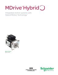
<strong>MODBUS</strong>/<strong>TCP</strong> <strong>Fieldbus</strong> <strong>manual</strong><br />
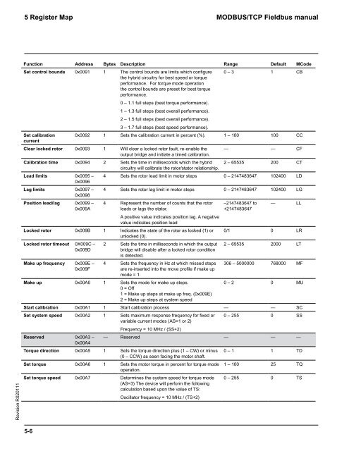
Function Address Bytes Description Range Default MCode<br />
Set control bounds 0x0091 1 The control bounds are limits which configure<br />
the hybrid circuitry for best speed or torque<br />
performance. For torque mode operation<br />
the control bounds are preset for best torque<br />
performance.<br />
0 – 1.1 full steps (best torque performance).<br />
1 – 1.3 full steps (best overall performance).<br />
2 – 1.5 full steps (best overall performance).<br />
3 – 1.7 full steps (best speed performance).<br />
0 – 3 1 CB<br />
Set calibration<br />
current<br />
0x0092 1 Sets the calibration current in percent (%). 1 – 100 100 CC<br />
Clear locked rotor 0x0093 1 Will clear a locked rotor fault, re-enable the<br />
output bridge and initiate a timed calibration.<br />
— — CF<br />
Calibration time 0x0094 2 Sets the time in milliseconds which the hybrid<br />
circuitry will calibrate the rotor/stator relationship.<br />
2 – 65535 200 CT<br />
Lead limits 0x0095 –<br />
0x0096<br />
4 Sets the rotor lead limit in motor steps 0 – 2147483647 102400 LD<br />
Lag limits 0x0097 –<br />
0x0098<br />
4 Sets the rotor lag limit in motor steps 0 – 2147483647 102400 LG<br />
Position lead/lag 0x0099 –<br />
0x009A<br />
4 Represent the number of counts that the rotor<br />
leads or lags the stator.<br />
A positive value indicates position lag. A negative<br />
value indicates position lead<br />
Locked rotor 0x009B 1 Indicates the state of the rotor as locked (1) or<br />
unlocked (0).<br />
Locked rotor timeout 0X009C –<br />
0x009D<br />
Make up frequency 0x009E –<br />
0x009F<br />
2 Sets the time in milliseconds in which the output<br />
bridge will disable after a locked rotor condition<br />
is detected.<br />
4 Sets the frequency in Hz at which missed steps<br />
are re-inserted into the move profile if make up<br />
mode = 1.<br />
Make up 0x00A0 1 Sets the mode for make up steps.<br />
0 = Off<br />
1 = Make up steps at make up freq. (0x009E)<br />
2 = Make up steps at system speed<br />
–2147483647 to<br />
+2147483647<br />
— LL<br />
0/1 0 LR<br />
2 – 65535 2000 LT<br />
306 – 5000000 768000 MF<br />
0 – 2 0 MU<br />
Start calibration 0x00A1 1 Start calibration process — — SC<br />
Set system speed 0x00A2 1 Sets maximum response frequency for fixed or<br />
variable current modes (AS=1 or 2)<br />
Frequency = 10 MHz / (SS+2)<br />
0 – 255 0 SS<br />
Reserved 0x00A3 –<br />
0x00A4<br />
— Reserved — — —<br />
Torque direction 0x00A5 1 Sets the torque direction plus (1 – CW) or minus<br />
(0 – CCW) as seen facing the motor shaft.<br />
0 – 1 1 TD<br />
Set torque 0x00A6 1 Sets the motor torque in percent for torque mode<br />
operation.<br />
1 – 100 25 TQ<br />
Set torque speed 0x00A7 Determines the system speed for torque mode<br />
(AS=3) The device will perform the following<br />
calculation based upon the value of TS:<br />
Oscillator frequency = 10 MHz / (TS+2)<br />
0 – 255 0 TS