Quick Reference IM483 & IM805 - Schneider Electric Motion USA
Quick Reference IM483 & IM805 - Schneider Electric Motion USA
Quick Reference IM483 & IM805 - Schneider Electric Motion USA

Create successful ePaper yourself
Turn your PDF publications into a flip-book with our unique Google optimized e-Paper software.
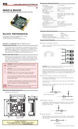
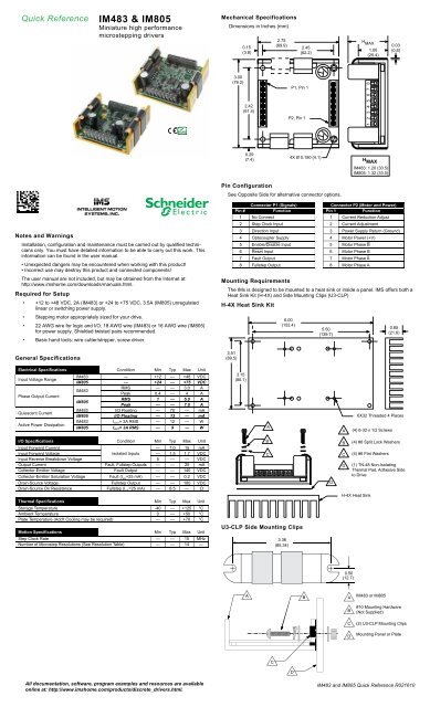
<strong>Quick</strong> <strong>Reference</strong> <strong>IM483</strong> & <strong>IM805</strong><br />
Miniature high performance<br />
microstepping drivers<br />
Notes and Warnings<br />
Installation, configuration and maintenance must be carried out by qualified technicians<br />
only. You must have detailed information to be able to carry out this work. This<br />
information can be found in the user manual.<br />
• Unexpected dangers may be encountered when working with this product!<br />
• Incorrect use may destroy this product and connected components!<br />
The user manual are not included, but may be obtained from the Internet at:<br />
http://www.imshome.com/downloads/manuals.html.<br />
Required for Setup<br />
• +12 to +48 VDC, 2A (<strong>IM483</strong>) or +24 to +75 VDC, 3.5A (<strong>IM805</strong>) unregulated<br />
linear or switching power supply.<br />
• Stepping motor appropriately sized for your drive.<br />
• 22 AWG wire for logic and I/O, 18 AWG wire (<strong>IM483</strong>) or 16 AWG wire (<strong>IM805</strong>)<br />
for power supply. Shielded twisted pairs recommended.<br />
• Basic hand tools: wire cutter/stripper, screw driver.<br />
General Specifications<br />
<strong>Electric</strong>al Specifications Condition Min Typ Max Unit<br />
Input Voltage Range<br />
Phase Output Current<br />
Quiescent Current<br />
Active Power Dissipation<br />
<strong>IM483</strong> — +12 — +48 VDC<br />
<strong>IM805</strong> — +24 — +75 VDC<br />
<strong>IM483</strong><br />
RMS<br />
Peak<br />
—<br />
0.4<br />
—<br />
—<br />
3.0<br />
4<br />
A<br />
A<br />
<strong>IM805</strong><br />
RMS<br />
Peak<br />
1<br />
—<br />
—<br />
—<br />
5.0<br />
7.0<br />
A<br />
A<br />
<strong>IM483</strong> I/O Floating — 70 — mA<br />
<strong>IM805</strong> I/O Floating — 13 — mA<br />
<strong>IM483</strong> IOUT= 3A RMS — 12 — W<br />
<strong>IM805</strong> IOUT= 3A RMS — 9 — W<br />
I/O Specifications Condition Min Typ Max Unit<br />
Input Forward Current<br />
— 7.0 15 mA<br />
Input Forward Voltage Isolated Inputs — 1.5 1.7 VDC<br />
Input Reverse Breakdown Voltage 5 — — VDC<br />
Output Current Fault, Fullstep Outputs — — 25 mA<br />
Collector-Emitter Voltage Fault Output — — 140 VDC<br />
Collector-Emitter Saturation Voltage Fault (I =25 mA) CS — — 0.2 VDC<br />
Drain-Source Voltage Fullstep Output — — 100 VDC<br />
Drain-Source On Resistance Fullstep (I =25 mA) CS — 6.5 — Ω<br />
Thermal Specifications Min Typ Max Unit<br />
Storage Temperature -40 — +125 °C<br />
Ambient Temperature 0 — +50 °C<br />
Plate Temperature (Add't Cooling may be required) — — +70 °C<br />
<strong>Motion</strong> Specifications Min Typ Max Unit<br />
Step Clock Rate — — 10 MHz<br />
Number of Microstep Resolutions (See Resolution Table) — — 14 —<br />
All documentation, software, program examples and resources are available<br />
online at: http://www.imshome.com/products/discrete_drivers.html.<br />
Mechanical Specifications<br />
Dimensions in Inches (mm)<br />
3.00<br />
(76.2)<br />
0.15<br />
(3.8)<br />
2.42<br />
(61.4)<br />
0.29<br />
(7.4)<br />
Pin Configuration<br />
See Opposite Side for alternative connector options.<br />
Connector P1 (Signals) Connector P2 (Motor and Power)<br />
Pin # Function Pin 1 Function<br />
1 No Connect 1 Current Reduction Adjust<br />
2 Step Clock Input 2 Current Adjustment<br />
3 Direction Input 3 Power Supply Return (Ground)<br />
4 Optocoupler Supply 4 Motor Power (+V)<br />
5 Enable/Disable Input 5 Motor Phase B<br />
6 Reset Input 6 Motor Phase B<br />
7 Fault Output 7 Motor Phase A<br />
8 Fullstep Output 8 Motor Phase A<br />
Mounting Requirements<br />
The IMx is designed to be mounted to a heat sink or inside a panel. IMS offers both a<br />
Heat Sink Kit (H-4X) and Side Mounting Clips (U3-CLP)<br />
H-4X Heat Sink Kit<br />
3.51<br />
(89.5)<br />
3.15<br />
(80.1)<br />
A<br />
B<br />
2.75<br />
(69.9)<br />
6.00<br />
(152.4)<br />
P2, Pin 1<br />
2.45<br />
(62.2)<br />
P1, Pin 1<br />
U3-CLP Side Mounting Clips<br />
4X Ø 0.190 (4.1)<br />
5.50<br />
(139.7)<br />
C C<br />
3.36<br />
(85.34)<br />
D<br />
A<br />
B<br />
D<br />
H MAX<br />
1 2 3 4 5 6 7 8<br />
1.00<br />
(25.4)<br />
H<br />
MAX<br />
<strong>IM483</strong>: 1.20 (30.5)<br />
<strong>IM805</strong>: 1.32 (33.5)<br />
0.03<br />
(0.8)<br />
0.85<br />
(21.6)<br />
6X32 Threaded 4 Places<br />
(4) 6-32 x 1/2 Screws<br />
(4) #6 Split Lock Washers<br />
(4) #6 Flat Washers<br />
(1) TN-48 Non-Isolating<br />
Thermal Pad, Adhesive Side<br />
to Drive<br />
H-4X Heat Sink<br />
0.50<br />
(12.7)<br />
A B<br />
A<br />
C<br />
D<br />
B<br />
C<br />
D<br />
<strong>IM483</strong> or <strong>IM805</strong><br />
#10 Mounting Hardware<br />
(Not Supplied)<br />
(2) U3-CLP Mounting Clips<br />
Mounting Panel or Plate<br />
<strong>IM483</strong> and <strong>IM805</strong> <strong>Quick</strong> <strong>Reference</strong> R021610
Controlling the Output Current<br />
A Current Adjustment Resistor is REQUIRED to operate the IMx driver. Optionally,<br />
the output current may be automatically reduced to a holding current level after a<br />
motion completes.<br />
Opto-Isolated Inputs<br />
A<br />
P2<br />
Steps/Rev<br />
MSEL 0<br />
SW1:1<br />
MSEL 1<br />
SW1:2<br />
MSEL 2<br />
SW1:3<br />
2 400<br />
Binary Resolutions<br />
0 0 0 0<br />
4 800 1 0 0 0<br />
8 1600 0 1 0 0<br />
16 3200 1 1 0 0<br />
32 6400 0 0 1 0<br />
64 12800 1 0 1 0<br />
128 25600 0 1 1 0<br />
256 51200 1 1 1 0<br />
Decimal Resolutions<br />
5 1000 0 0 0 1<br />
10 2000 1 0 0 1<br />
25 5000 0 1 0 1<br />
50 10000 1 1 0 1<br />
125 25000 0 0 1 1<br />
250 50000 1 0 1 1<br />
Resolution<br />
Microsteps/Step<br />
3 2 1<br />
Connecting Motor and Motor Power<br />
This document shows connection of<br />
a 4-lead stepping motor. For 6 and<br />
8-lead motor connection see the product<br />
manual. Use the table on the right<br />
to determine the acceptable per-phase<br />
inductance.<br />
Stepping Motor<br />
B<br />
Phase B<br />
Phase B<br />
Phase A<br />
Phase A<br />
Current Limiting Resistor Values<br />
+VDC 5 10 12 15 24<br />
RLIMIT – 681 1000 1300 2670<br />
Controller<br />
Output<br />
RLIMIT *<br />
1/4 W 1%<br />
Open Collector Interface<br />
Isolated Input<br />
Setting the Microstep Resolution<br />
OFF/HIGH/1<br />
+<br />
-<br />
1<br />
2<br />
3<br />
4<br />
MSEL Switch<br />
ON/LOW/0<br />
Minimum Required Connections<br />
* All Opto-Isolated inputs<br />
should be referenced to<br />
the Opto Supply Ground<br />
for Isolation, Not Drive<br />
Power Ground.<br />
+5 VDC<br />
Supply*<br />
Step Clock**<br />
Direction Switch**<br />
1<br />
2<br />
3<br />
4<br />
5<br />
6<br />
7<br />
8<br />
P1<br />
8 7 6 5 4 3<br />
P2<br />
A<br />
B<br />
Current Adjust Resistor<br />
(1/8W 1%Ω) See EQ. A.<br />
Reduction Adjust Resistor<br />
(1/8W 1%Ω) See EQ. B.<br />
EQ. A<br />
RADJ = IPEAK X 500<br />
EQ. B<br />
R RED<br />
=<br />
I I<br />
RUN X HOLD<br />
500 X I I<br />
RUN - HOLD<br />
+V<br />
Max Inductance Per Phase (mH)<br />
<strong>IM483</strong> <strong>IM805</strong><br />
+12 2.5 —<br />
+24 5 5<br />
+40 8 8<br />
+48 10 10<br />
+75 — 15<br />
Linear Unregulated or Switch Mode<br />
<strong>IM483</strong>: +12 to +48 VDC ± 10% Ripple<br />
<strong>IM805</strong>: +24 to +75 VDC ± 10% Ripple<br />
Controller<br />
Output<br />
1 = MSEL0<br />
2 = MSEL1<br />
3 = MSEL2<br />
4 = MSEL3<br />
8<br />
7<br />
6<br />
5<br />
P2<br />
4<br />
3<br />
2<br />
1<br />
+5 VDC<br />
TTL Interface<br />
Phase A<br />
Phase A<br />
Phase B<br />
Phase B<br />
+V<br />
GND<br />
R ADJ<br />
** If an Opto Supply voltage greater than +5 VDC is used, a current<br />
limiting resistor is REQUIRED in series with the Input!<br />
-<br />
Power<br />
Supply<br />
MSEL 3<br />
SW1:4<br />
+<br />
Opto Supply P1:4<br />
Isolated Input<br />
The following illustration shows the minimum connection requirements for operating<br />
the IMx. For use and interface of the other I/O Points please refer to the full product<br />
manual.<br />
Stepping Motor<br />
Copyright © <strong>Schneider</strong> <strong>Electric</strong> <strong>Motion</strong> <strong>USA</strong> www.schneider-electric-motion.us<br />
+<br />
-<br />
Power<br />
Supply<br />
Alternate Connector Options - 8-Pins at P1<br />
The pin-out is identical to standard IMx products.<br />
IMx-8P2 - 8-Pin Posts at Connectors at P1 and P2<br />
0.200<br />
(5.1)<br />
0.720<br />
(18.3)<br />
0.820<br />
(20.8)<br />
Connector P1<br />
IMx-PLG - 8-Pin Locking Pluggable Connectors at P1 and P2<br />
0.200<br />
(5.1)<br />
0.472<br />
(12.0)<br />
Connector P1 and P2<br />
8X 0.025 (0.64)<br />
SQ. Post Tin<br />
Plated Bronze<br />
8X 0.040 (1.02)<br />
SQ. Post Tin<br />
Plated Bronze<br />
0.200<br />
(5.1)<br />
0.811<br />
(20.6)<br />
0.914<br />
(23.2)<br />
Alternate Connector Options - 34-Pins at P1<br />
The pin-out allows for additional signals. See table below.<br />
P2:1<br />
Connector P2<br />
P1:1<br />
Orientation<br />
IMx-34P1: 34-Pin Header at P1, Standard Screw Terminal at P2<br />
0.41<br />
(10.4)<br />
1<br />
18<br />
0.500<br />
(12.7)<br />
17<br />
34<br />
8X 0.045 (1.14)<br />
SQ. Post Tin<br />
Plated Bronze<br />
IMx-34P1-8P2: 34-Pin Posts at Connectors at P1 and 8-Pin Posts at P2<br />
0.100<br />
(2.54)<br />
0.520<br />
0.800 (13.2)<br />
(20.3)<br />
BB-34 Breakout Board<br />
8X 0.025 (0.64)<br />
SQ. Post Tin<br />
Plated Bronze<br />
Connector P1<br />
0.220<br />
(5.6)<br />
0.025<br />
(0.6)<br />
0.100<br />
(2.54)<br />
0.100<br />
(2.54)<br />
Connector P1<br />
0.200<br />
(5.1)<br />
0.811<br />
(20.6)<br />
0.914<br />
(23.2)<br />
34X 0.025 (0.64)<br />
SQ. Posts Tin<br />
Plated Bronze<br />
Pin # Function Pin # Function<br />
0.100<br />
(2.54)<br />
8X 0.045 (1.14)<br />
SQ. Post Tin<br />
Plated Bronze<br />
Connector P2<br />
3 Resolution Select 3 16, 26 On-Full-Step Output<br />
4 Step Clock Input 21 Step Clock Output (Non-Isolated)*<br />
6 Direction Input 22 Direction Output (Non-Isolated)*<br />
8 Optocoupler Supply 23 Resolution Select 0<br />
10 Enable/Disable Input 24 Resolution Select 1<br />
12 Reset Input 25 Resolution Select 2<br />
14 Fault Output 27 Logic Ground (Non-Isolated)<br />
*Step/Direction outputs follow the inputs at a 1:1 Ratio.<br />
0.107<br />
(2.72)<br />
1<br />
18<br />
2.441<br />
(62.00)<br />
Pin 10: Enable Input<br />
Pin 8: Opto Supply<br />
Pin 6: Direction Input<br />
Pin 3: MSEL3<br />
1<br />
18<br />
Pin 21: Step Out<br />
Pin 22: Direction Out<br />
Pin 23: MSEL0<br />
Pin 24: MSEL2<br />
2.635<br />
(66.92)<br />
17<br />
34<br />
2X Ø 0.155<br />
(3.94)<br />
0.780<br />
(19.81)<br />
17<br />
34<br />
1.050<br />
(26.67)<br />
Pin 12: Reset Input<br />
Pin 14: Fault Output<br />
Pin 16: On-Full-Step Output<br />
Pin 27: Ground<br />
Pin 26: On-Full-Step Output<br />
Pin 25: MSEL1