

Rockford Systems Safeguarding Devices Catalog
FREE, 80-page full-color catalog that features a wide-range of safeguarding devices and other safety-related products for updating hazardous machinery and processes. These devices are designed for point-of-operation safeguarding as well as for auxiliary guarding and large work-envelope safeguarding. Some of the products in this catalog include presence-sensing devices, area scanning devices, tower light assemblies, Detect-A-Finger® drop-probe devices, and pressure sensitive safety mats. These products can be used to safeguard fabricating machines, metal-cutting machines, material handling equipment, woodworking machines, and more.These safeguarding devices are designed to meet or exceed the OSHA regulations and ANSI standards.
FREE, 80-page full-color catalog that features a wide-range of safeguarding devices and other safety-related products for updating hazardous machinery and processes. These devices are designed for point-of-operation safeguarding as well as for auxiliary guarding and large work-envelope safeguarding. Some of the products in this catalog include presence-sensing devices, area scanning devices, tower light assemblies, Detect-A-Finger® drop-probe devices, and pressure sensitive safety mats. These products can be used to safeguard fabricating machines, metal-cutting machines, material handling equipment, woodworking machines, and more.These safeguarding devices are designed to meet or exceed the OSHA regulations and ANSI standards.

Create successful ePaper yourself
Turn your PDF publications into a flip-book with our unique Google optimized e-Paper software.
I<br />
N<br />
I<br />
M<br />
U<br />
M<br />
I<br />
N<br />
C<br />
H<br />
I<br />
N<br />
I<br />
O<br />
N<br />
GATE (MOVEABLE BARRIER) DEVICES<br />
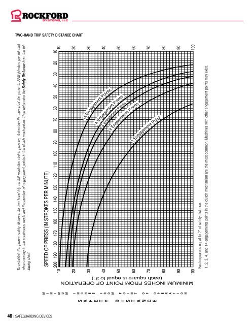
TWO-HAND TRIP SAFETY DISTANCE CHART<br />
GATE OR MOVABLE BARRIER DEVICE<br />
To establish the proper safety distance for two-hand trip on full-revolution-clutch presses, determine the speed of the press in SPM (strokes per minute)<br />
when running in the continuous mode and the number of engagement points in the clutch mechanism. Then determine the Safety Distance from the following<br />
chart.<br />
SPEED OF PRESS (IN STROKES PER MINUTE)<br />
200 190 180 170 160 150 140 130 120 110 100 90 80 70 60 50 40 30 20 10<br />
10<br />
10<br />
20<br />
20<br />
30<br />
40<br />
50<br />
60<br />
70<br />
80<br />
14 Engagement Points<br />
4 Engagement Points<br />
3 Engagement Points<br />
2 Engagement Points<br />
1 Engagement Point<br />
30<br />
40<br />
50<br />
60<br />
70<br />
80<br />
90<br />
90<br />
100<br />
100<br />
Each square is equal to 2” of safety distance.<br />
1, 2, 3, 4, and 14 engagements points in the clutch mechanism are the most common. Machines with other engagement points may exist.<br />
Example of a Type A Gate Package<br />
INTRODUCTION<br />
Why use a gate device? According to the OSHA and ANSI standards,<br />
“operators must be prevented from inadvertently placing their hands<br />
or any other body parts in the point of operation during the die-closing<br />
portion of the press stroke.” The movable gate device uses a proven<br />
method of placing a physical barrier between the operator and the<br />
point-of-operation hazard during the die-closing portion of the press<br />
stroke.<br />
Other advantages of gate devices include the following:<br />
1. Operators are not physically attached with wristlets to the machine<br />
as they are when using a pullback or restraint device. This means<br />
operator resistance is minimized because of the nonrestrictive<br />
design allowing more freedom of movement.<br />
2. These devices protect other employees in the machine area.<br />
3. A foot switch can be used to actuate the press. This minimizes stress<br />
to the hands and arms which can be caused by palm buttons.<br />
Two types of gates are available. The first is a type A gate. It protects the<br />
operator during the entire machine cycle. This means the gate will not<br />
open until after the machine’s cycle is complete and stopped (usually in<br />
the up position). Type A gates are the only gates that should be used on<br />
full-revolution-clutch presses.<br />
The second is a type B gate. It protects the operator during the<br />
downstroke only. The gate can open after the hazardous portion<br />
of the cycle has passed. Both type A and B gates can be used on<br />
part-revolution-clutch machines, hydraulic presses, and other cyclic<br />
machines where material is being manually fed.<br />
TYPE A GATE SEQUENCE OF OPERATION<br />
When the actuating means (palm buttons or foot switch) is operated,<br />
air pressure is released from the bottom of the gate-operating cylinder.<br />
This allows the gate to descend by gravity. Once the gate is fully down,<br />
a gate-down proximity switch senses this and the machine is allowed<br />
to make a cycle. If the gate cannot complete its downward travel, this<br />
gate-down proximity switch will not sense the gate and will prevent a<br />
machine cycle.<br />
If the actuating means is released before the machine starts its cycle,<br />
the gate returns to the full open position with a type A gate. When the<br />
machine is actually making a cycle, air pressure is applied to the top<br />
of the gate-operating cylinder which holds the gate down and prevents<br />
it from being raised until the machine has completed its cycle. If the<br />
machine malfunctions and does not stop at the end of a normal cycle,<br />
the gate remains in the closed position.<br />
According to ANSI (see next page), the gate must open after every<br />
cycle in order to reset the antirepeat system. If this does not happen,<br />
the machine will not make another stroke. To accomplish this, the gate<br />
control requires a signal from the machine at the open position. This<br />
signal is normally obtained from a photo-sensor or limit switch operated<br />
by a cam. Actuation of the limit switch is accomplished by the rotation of<br />
the crankshaft or any other member of the machine which makes one<br />
cycle or oscillates along one axis every stroke.<br />
When a type A gate package is furnished for a full-revolution-clutch<br />
machine, the top-dead-center signal is provided by a limit switch<br />
assembly.<br />
TYPE B GATE SEQUENCE OF OPERATION<br />
The type B gate operates in a similar manner as the type A gate. When<br />
the actuating means (palm buttons or foot switch) is operated, air<br />
pressure is released from the bottom of the gate-operating cylinder.<br />
This allows the gate to descend by gravity. Once the gate is fully down,<br />
a gate-down proximity switch senses this and the machine is allowed<br />
to begin the cycle. If the gate cannot complete its downward travel, this<br />
gate-down proximity switch will not sense the gate and will prevent a<br />
machine cycle.<br />
MINIMUM INCHES FROM POINT OF OPERATION<br />
(each square is equal to 2")<br />
S<br />
A<br />
F<br />
E<br />
T<br />
Y<br />
D<br />
I<br />
S<br />
T<br />
A<br />
N<br />
C<br />
E<br />
M<br />
E<br />
S<br />
F<br />
R<br />
O<br />
M<br />
P<br />
O<br />
T<br />
O<br />
F<br />
O<br />
P<br />
E<br />
R<br />
A<br />
T<br />
46 | SAFEGUARDING DEVICES SAFEGUARDING DEVICES | 47


