

Rockford Systems Safeguarding Devices Catalog
FREE, 80-page full-color catalog that features a wide-range of safeguarding devices and other safety-related products for updating hazardous machinery and processes. These devices are designed for point-of-operation safeguarding as well as for auxiliary guarding and large work-envelope safeguarding. Some of the products in this catalog include presence-sensing devices, area scanning devices, tower light assemblies, Detect-A-Finger® drop-probe devices, and pressure sensitive safety mats. These products can be used to safeguard fabricating machines, metal-cutting machines, material handling equipment, woodworking machines, and more.These safeguarding devices are designed to meet or exceed the OSHA regulations and ANSI standards.
FREE, 80-page full-color catalog that features a wide-range of safeguarding devices and other safety-related products for updating hazardous machinery and processes. These devices are designed for point-of-operation safeguarding as well as for auxiliary guarding and large work-envelope safeguarding. Some of the products in this catalog include presence-sensing devices, area scanning devices, tower light assemblies, Detect-A-Finger® drop-probe devices, and pressure sensitive safety mats. These products can be used to safeguard fabricating machines, metal-cutting machines, material handling equipment, woodworking machines, and more.These safeguarding devices are designed to meet or exceed the OSHA regulations and ANSI standards.

Create successful ePaper yourself
Turn your PDF publications into a flip-book with our unique Google optimized e-Paper software.
GATE (MOVEABLE BARRIER) DEVICES<br />
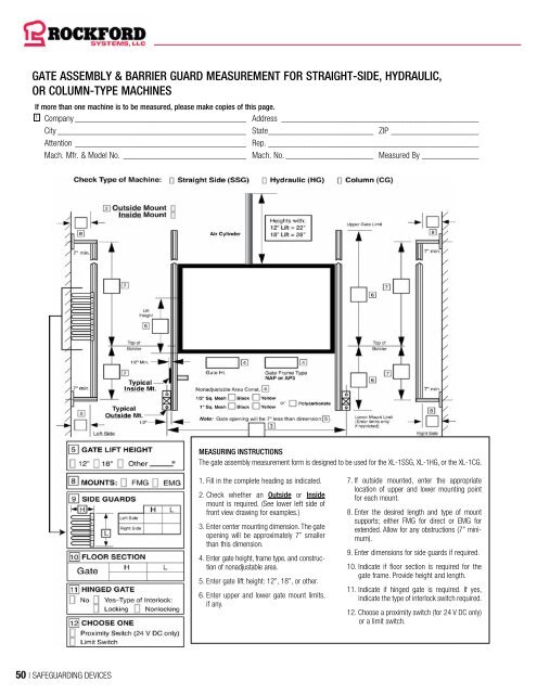
GATE ASSEMBLY & BARRIER GUARD MEASUREMENT FOR STRAIGHT-SIDE, HYDRAULIC,<br />
OR COLUMN-TYPE MACHINES<br />
If more than one machine is to be measured, please make copies of this page.<br />
1 Company________________________________________ Address______________________________________________<br />
City____________________________________________ State_________________________ ZIP_____________________<br />
Attention________________________________________ Rep._________________________________________________<br />
Mach. Mfr. & Model No._____________________________ Mach. No._____________________ Measured By______________<br />
MEASURING INSTRUCTIONS<br />
The gate assembly measurement form is designed to be used for the XL-1SSG, XL-1HG, or the XL-1CG.<br />
1. Fill in the complete heading as indicated.<br />
2. Check whether an Outside or Inside<br />
mount is required. (See lower left side of<br />
front view drawing for examples.)<br />
3. Enter center mounting dimension. The gate<br />
opening will be approximately 7” smaller<br />
than this dimension.<br />
4. Enter gate height, frame type, and construction<br />
of nonadjustable area.<br />
5. Enter gate lift height: 12”, 18”, or other.<br />
6. Enter upper and lower gate mount limits,<br />
if any.<br />
7. If outside mounted, enter the appropriate<br />
location of upper and lower mounting point<br />
for each mount.<br />
8. Enter the desired length and type of mount<br />
supports; either FMG for direct or EMG for<br />
extended. Allow for any obstructions (7” minimum).<br />
9. Enter dimensions for side guards if required.<br />
10. Indicate if floor section is required for the<br />
gate frame. Provide height and length.<br />
11. Indicate if hinged gate is required. If yes,<br />
indicate the type of interlock switch required.<br />
12. Choose a proximity switch (for 24 V DC only)<br />
or a limit switch.<br />
MEASURING INSTRUCTIONS FOR GATE ASSEMBLY MODELS XL-2G THROUGH XL-6G<br />
The following instructions are for measuring XL-2G through XL-6G<br />
gate assemblies and barrier guards. The basic information necessary<br />
to quote or fabricate any of the listed gates and barrier guards is the<br />
size of the gate, the frame type, nonadjustable area construction,<br />
height of panel(s), panel segments (if required), and mounts to attach<br />
the gate and guards to the machine. The length of all panels will be<br />
determined by <strong>Rockford</strong> <strong>Systems</strong>.<br />
The following instructions are purposely kept as simple as possible to<br />
avoid long explanations of the many variations available.<br />
1. Fill in the complete heading as indicated.<br />
2. Check appropriate gate model number.<br />
XL-2G = 2 panel and gate<br />
XL-3G = 3 panel and gate<br />
XL-4G = 4 panel and gate<br />
XL-5G = 5 panel and gate<br />
XL-6G = 6 panel and gate<br />
(If any panels are not required, cross them out in the panel chart.)<br />
3. Measure and record the bolster width and depth.<br />
4. Measure web width of frame, if the barrier guard is to be mounted to<br />
the front of the frame behind the bolster plate.<br />
5. Measure and record the distance from the mounting point of the<br />
guard on the frame of the machine to the rear of the bolster. Measure<br />
and record the outside width of the press frame behind the bolster plate.<br />
6. Indicate desired position of L and R panels and gate relative<br />
to the bolster. Drawing shows panels and gate outbound of the<br />
bolster. If panels or gate should be inbound, enter minus (-) dimensions,<br />
or on the bolster, enter zero.<br />
7. Enter the minimum and maximum feedline heights. Enter distance<br />
from the bottom of the gate to bolster (usually 0 inches). If below bolster,<br />
enter inches.<br />
8. Measure and record the clearance from the flywheel cover or<br />
obstruction to the top of the bolster. This dimension could affect the<br />
panel height if the panel is to be swung underneath. Indicate if view is<br />
from left or right side of the machine.<br />
When measuring, be sure the gate will lift completely<br />
without hitting any obstruction.<br />
9. Measure and record the feedline depth.<br />
10. Indicate the gate lift height required, normally 12” or 18” is sufficient.<br />
11. Indicate mounts required for LR, L, R, or RR panels.<br />
SFM Side Frame Mount<br />
SFM-7 Side Frame Mount (3”, 5”, or 7”)<br />
SFM-24 Side Frame Mount up to 24”<br />
FFM Front Frame Mount<br />
Note: The panel will begin approximately 2½” from the mounting point<br />
with the SFM, SFM-7, or SFM-24 mount. The panel will begin<br />
approximately 1” from the mounting point with the FFM mount.<br />
12. Indicate frame type for each panel and gate.<br />
NAP<br />
AP1<br />
AP2<br />
AP3<br />
AP4<br />
AP5<br />
API<br />
Nonadjustable Panel<br />
Adjustable Panel (1/2 frame)<br />
Adjustable Panel (5/8 frame)<br />
Adjustable Panel (3/4 frame)<br />
Adjustable Panel (Center—Full frame)<br />
Adjustable Panel (Lower—Full frame)<br />
Adjustable Panel (Inclinable)<br />
The gate can ONLY be NAP or AP3.<br />
13. Indicate the construction of the nonadjustable area for each panel.<br />
B<br />
B1<br />
Y<br />
Y1<br />
PC<br />
1/2” Sq. Black Mesh (16 gauge)<br />
1” Sq. Black Mesh (12 gauge)<br />
1/2” Sq. Yellow Mesh (16 gauge)<br />
1” Sq. Yellow Mesh (12 gauge)<br />
Polycarbonate (3/16” thick)<br />
The gate is normally polycarbonate.<br />
14. Indicate height of each panel.<br />
15. Indicate length of each panel. <strong>Rockford</strong> <strong>Systems</strong> will determine<br />
length(s) based on other dimensions provided.<br />
16. Indicate panel segment type, height, length, and if hinged or<br />
nonhinged, if required.<br />
FS<br />
AS<br />
PCS<br />
ES<br />
Feeder Segment<br />
Adjustable Segment<br />
Polycarbonate Segment<br />
Empty Segment<br />
17. Indicate if L, LF, Gate, RF, or R panels require an interlock switch<br />
and choose locking or nonlocking.<br />
18. Indicate if L, LF, Gate, RF, or R panel needs to be hinged (L or R).<br />
The gate ALWAYS hinges left.<br />
19. Indicate if hairpins are required in place of LR or RR panel. The<br />
number of hairpins supplied will be determined by the height of the L or<br />
R panel. Indicate the height of hairpins required in the box.<br />
20. Indicate if roof section(s) are required. Provide height and length.<br />
21. Indicate if floor section(s) are required. Provide height and length.<br />
22. Choose proximity switch (for 24 V DC only) or limit switch.<br />
50 | SAFEGUARDING DEVICES SAFEGUARDING DEVICES | 51


