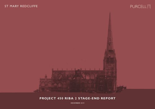
St Mary Redcliffe Project 450 RIBA 2 Stage End Report

You also want an ePaper? Increase the reach of your titles
YUMPU automatically turns print PDFs into web optimized ePapers that Google loves.
ST MARY REDCLIFFE<br />
PROJECT <strong>450</strong> <strong>RIBA</strong> 2 STAGE-END REPORT<br />
DECEMBER 2019
Dan Talkes<br />
<strong>RIBA</strong> AABC<br />
Old Police <strong>St</strong>ation,<br />
6 <strong>St</strong> Peters Court,<br />
Bedminster Parade,<br />
Bristol,<br />
BS3 4AQ<br />
dan.talkes@purcelluk.com<br />
+44 (0)117 910 1060<br />
www.purcelluk.com<br />
All rights in this work are reserved. No part of this work may be<br />
reproduced, stored or transmitted in any form or by any means<br />
(including without limitation by photocopying or placing on a website)<br />
without the prior permission in writing of Purcell except in accordance<br />
with the provisions of the Copyright, Designs and Patents Act 1988.<br />
Applications for permission to reproduce any part of this work should<br />
be addressed to Purcell at info@purcelluk.com.<br />
Undertaking any unauthorised act in relation to this work may<br />
result in a civil claim for damages and/or criminal prosecution.<br />
Any materials used in this work which are subject to third party<br />
copyright have been reproduced under licence from the copyright<br />
owner except in the case of works of unknown authorship as<br />
defined by the Copyright, Designs and Patents Act 1988. Any<br />
person wishing to assert rights in relation to works which have<br />
been reproduced as works of unknown authorship should<br />
contact Purcell at info@purcelluk.com.<br />
Purcell asserts its moral rights to be identified as the author of<br />
this work under the Copyright, Designs and Patents Act 1988.<br />
Purcell® is the trading name of Purcell Miller Tritton LLP.<br />
© Purcell 2019
CONTENTS<br />
1.0 PROJECT TEAM<br />
2.0 INTRODUCTION<br />
3.0 PROJECT TIMELINE<br />
4.0 DESIGN DEVELOPMENT<br />
4.1 STRUCTURES<br />
4.2 MECHANICAL & ELECTRICAL SERVICES AND ENVIRONMENTAL SUSTAINABILITY<br />
4.3 LANDSCAPE<br />
4.4 SCHEME UPDATES<br />
4.5 CURRENT PROPOSALS<br />
4.6 MATERIALITY<br />
4.7 DESIGN INTENT DETAILS<br />
4.8 AREAS OF FURTHER INVESTIGATION<br />
5.0 CONSULTATION<br />
6.0 COST PLAN<br />
7.0 RISK REGISTER<br />
8.0 PROGRAMME<br />
9.0 NEXT STEPS<br />
10.0 APPENDICES<br />
10.1 ARBORICULTURAL SURVEY<br />
10.2 ECOLOGICAL ASSESSMENT<br />
10.3 MEP STRATEGIES
1.0 PROJECT TEAM<br />
1.<br />
Client<br />
4.<br />
Mechanical & Electrical Performance<br />
7.<br />
Heritage Asset Review<br />
<strong>St</strong> <strong>Mary</strong> <strong>Redcliffe</strong> Church<br />
<strong>Redcliffe</strong><br />
Bristol<br />
BS1 6RA<br />
Rev Dan Tyndall<br />
0117 231 0060<br />
dan.tyndall@stmaryredcliffe.co.uk<br />
Qoda Consulting<br />
1 Ram Court<br />
Wicklesham Lodge<br />
Faringdon<br />
SN7 7PN<br />
Oliver Fuller – Principal Sustainability Engineer<br />
01367 245 960<br />
oliver.fuller@qodaconsulting.com<br />
8.<br />
Rita McLean & Jane Arthur<br />
Museums & Heritage Consultants<br />
Outline Interpretation <strong>St</strong>rategy<br />
Imagemakers<br />
Exhibition Design, Heritage Planning & Installation<br />
2.<br />
Architect<br />
5.<br />
Cost Consultancy<br />
9.<br />
Community Consultation<br />
Purcell<br />
The Old Police <strong>St</strong>ation<br />
Bedminster Parade<br />
Bristol<br />
BS3 4AQ<br />
Gleeds<br />
1400 Bristol Parkway North<br />
Newbrick Road<br />
Bristol<br />
BS34 8YU<br />
10.<br />
Vivid Regeneration<br />
Positive change for people & place<br />
Heritage Business Plan<br />
Dan Talkes – Consultant<br />
0117 910 1060<br />
dan.talkes@purcelluk.com<br />
Mike Jones – Associate Director<br />
0117 317 3200<br />
mike.jones@gleeds.co.uk<br />
Glevum<br />
Heritage Business Consulting<br />
11.<br />
Fundraising Review<br />
3.<br />
<strong>St</strong>ructures<br />
Integral Engineering<br />
First Floor<br />
Riverside South<br />
Walcot Yard<br />
Walcot <strong>St</strong>reet<br />
Bath<br />
BA1 5BG<br />
Margaret Cooke – Director<br />
01225 859 657<br />
mc@integral-engineering.co.uk<br />
6.<br />
Landscape Design<br />
LUC<br />
12th Floor, Colston Tower<br />
Colston <strong>St</strong>reet<br />
Bristol<br />
BS1 4XE<br />
Edward Tarratt – Associate<br />
0117 929 1997<br />
edward.tarrett@landuse.co.uk<br />
Eric Grounds<br />
Charity Consultant & Campaign Director
2.0 INTRODUCTION<br />
Funded jointly by both the Canynges Society and the Church Lands Charity, to whom we extend<br />
our thanks, <strong>RIBA</strong> 2 has focussed on the rigorous, robust, and increasingly-detailed development<br />
of the emerging scheme design<br />
Now informed by specialist consultant inputs, further public and stakeholder consultation, this<br />
work culminates in a fully-costed, coordinated and updated set of architectural proposals that<br />
bring further certainty to both P<strong>450</strong>’s progression and the eventual realisation of its undoubted<br />
benefits for both the Congregation and Community of <strong>St</strong> <strong>Mary</strong> <strong>Redcliffe</strong>
3.0 PROJECT TIMELINE<br />
Emerging from <strong>RIBA</strong> 1 with a:<br />
• Clearer definition of need<br />
• Substantially reduced spatial brief<br />
• Consequently, more proportionate architectural proposal<br />
The <strong>Project</strong> Team have consciously structured the <strong>RIBA</strong> 2 activities around a considered series<br />
of workshops, consultations, and reviews to enable iterative design, and ensure the project’s<br />
development is coordinated, efficient, and effectively communicated<br />
The resulting 4 months of intense exploration are summarised within the adjacent timeline and<br />
following report<br />
‘To serve our parish better, we<br />
must serve our visitors better’<br />
Rev Dan Tyndall, Vicar of <strong>St</strong> <strong>Mary</strong> <strong>Redcliffe</strong>
<strong>Project</strong> <strong>450</strong> Board Review<br />
Instruction to Proceed to <strong>RIBA</strong> <strong>St</strong>age 2<br />
Sharing Ideas - Consultation with Bristol DAC<br />
Design Team Meeting / Workshops<br />
<strong>Project</strong> Board / Development Funders’ Update<br />
Sharing Ideas - Public / <strong>St</strong>akeholder Consultation<br />
Design Team Meeting / Workshops<br />
<strong>Project</strong> Board / Development Funders’ Update<br />
PCC Update / Review<br />
Design Team Meeting / Workshops<br />
<strong>Project</strong> Board / Development Funders’ Update<br />
Sharing Ideas - Consultation with Bristol DAC<br />
Design Team Meeting / Workshops<br />
<strong>Project</strong> Board / Development Funders’ Update<br />
PCC Update / Review<br />
Sharing Ideas - <strong>St</strong>akeholder Consultation<br />
Design Team Meeting / Workshops<br />
<strong>Project</strong> Board / Development Funders’ Update<br />
2019 AUG SEP OCT<br />
NOV DEC
4.0 DESIGN DEVELOPMENT<br />
In accordance with the <strong>RIBA</strong> Plan of Work 2013, the design development during <strong>RIBA</strong> 2 has<br />
focussed on developing:<br />
• The concept design, including:<br />
• Outline proposals for structures, services, sustainability, and landscape<br />
• Preliminary cost information, including a regularly monitored and updated cost plan<br />
• An updated project brief and programme<br />
Additionally, acknowledging the indisputably high significance of <strong>St</strong> <strong>Mary</strong> <strong>Redcliffe</strong>, confirmed by<br />
its Grade I Listing, and the undoubted sensitivity of its context, extensive public and stakeholder<br />
consultation has been undertaken (as detailed within Section 5.0) to ensure continued<br />
engagement, project support, and minimise the risk of abortive work<br />
Each of the coordinated co-consultant inputs is summarised within the following sub-sections and,<br />
as noted elsewhere, has been facilitated via both regular Design Workshops and Design Team<br />
Meetings, the latter also attended by:<br />
Dan Tyndall - Vicar of <strong>St</strong> <strong>Mary</strong> <strong>Redcliffe</strong><br />
Rhys Williams - P<strong>450</strong> <strong>Project</strong> Coordinator and Research Assistant<br />
Richard Wallace - <strong>St</strong> <strong>Mary</strong> <strong>Redcliffe</strong> Church Warden<br />
Marcus Chantrey - <strong>St</strong> <strong>Mary</strong> <strong>Redcliffe</strong> Inspecting Architect<br />
Consequently, all design decisions have been subject to the welcome scrutiny of key church<br />
officers and laypeople, and also informed by the specialist knowledge of the church’s approved<br />
inspector<br />
Finally, the design development has also been informed by the results of the specialist<br />
Arboricultural and Ecological Surveys that are appended in Section 10.1 & 10.2<br />
The <strong>RIBA</strong> Plan of Work, against which P<strong>450</strong>’s progression is<br />
mapped, for the purposes of both project planning and reporting
4.1 STRUCTURES<br />
Undertaken by Integral Engineering, the <strong>St</strong>ructural <strong>Report</strong> documents the following civil and<br />
structural information identified, recorded, and developed during <strong>RIBA</strong> <strong>St</strong>age 2:<br />
1. Ground Conditions & Site Investigation<br />
2. Drainage<br />
3. Site Constraints<br />
4. Substructure<br />
5. Superstructure<br />
6. Design Criteria<br />
Additionally, the report has identified and informed the structural risks and potential mitigations<br />
that are embedded within the <strong>Project</strong> Risk Register in Section 7.0<br />
2. Ground Conditions & Site Investigation<br />
2. Ground Conditions & Site Investigation<br />
The BGS geology maps show the site to be in the area of an outcrop of <strong>Redcliffe</strong><br />
Sandstone possibly overlain by River Terrace Deposits to the north of the site.<br />
2. Ground 1. Ground Conditions Conditions & Site & Investigation<br />
The BGS geology maps show the site Site to Investigation<br />
be in the area of an outcrop of <strong>Redcliffe</strong><br />
Sandstone possibly overlain by River Terrace Deposits to the north of the site.<br />
The BGS geology maps show the site to be in the area of an outcrop of <strong>Redcliffe</strong><br />
The BGS geology maps show the site to be in the area of an outcrop of <strong>Redcliffe</strong> Sandstone<br />
Sandstone possibly overlain by River Terrace Deposits to the north of the site.<br />
possibly overlain by River Terrace Deposits to the north of the site<br />
Three historic boreholes have been identified in close proximity to the site with the closest being south of the site<br />
to the rear of Colston Parade. The borehole was drilled to a depth of 10m in 1970 and encountered approximately<br />
1.0m made ground over 1.2m very stiff red silty clay over red and grey sandstone<br />
If a lightweight construction is adopted a shallow spread foundation is likely to be suitable apart from in the<br />
location of the events space in the south courtyard which is likely to require a mini piled or screw piled foundation<br />
due to the presence of existing tree roots<br />
Figure 4. <strong>St</strong> <strong>Mary</strong> <strong>Redcliffe</strong> geology<br />
An intrusive site investigation (SI) will be required to inform the design of the proposed<br />
foundations which will need to encompass the following;<br />
Figure 2. BGS Superficial Deposits<br />
Figure 2. BGS Superficial Deposits<br />
Figure 3. BGS Bedrock<br />
Figure 3. BGS Bedrock<br />
Figure 2. BGS Superficial Deposits<br />
Figure 3. BGS Bedrock<br />
Figure 4. North churchyard foundations<br />
Figure 4. <strong>St</strong> <strong>Mary</strong> <strong>Redcliffe</strong> geology<br />
Figure 4. <strong>St</strong> <strong>Mary</strong> <strong>Redcliffe</strong> geology<br />
Three historic boreholes have been identified in close proximity to the site with the<br />
breath<br />
closest being south of the site to the rear of Colston Parade. The borehole was drilled<br />
Three historic boreholes have been identified in close proximity to the site with the<br />
to a depth of 10m in 1970 and encountered approximately 1.0m made ground over<br />
closest being south of the site to the rear of Colston Parade. The borehole was drilled<br />
1.2m very stiff red silty clay over red and grey sandstone.<br />
to a depth of 10m in 1970 and encountered approximately 1.0m made ground over<br />
If<br />
1.2m<br />
a lightweight<br />
very stiff red<br />
construction<br />
silty clay<br />
is<br />
over<br />
adopted<br />
red and<br />
a shallow<br />
grey sandstone.<br />
spread foundation is likely to be<br />
suitable apart from in the location of the events space in the south courtyard which is<br />
If a lightweight construction is adopted a shallow spread foundation is likely to be<br />
likely to require a mini piled or screw piled foundation due to the presence of existing<br />
suitable apart from in the location of the events space in the south courtyard which is<br />
tree roots.<br />
likely to require a mini piled or screw piled foundation due to the presence of existing<br />
tree roots.<br />
Made ground & burial ground<br />
Choir Vestry<br />
Made ground & burial ground<br />
Screw piles between tree<br />
Events space<br />
roots, building<br />
Screw piles between tree<br />
Events space<br />
suspended to allow trees to<br />
Sandstone roots, building<br />
Figure 5. South churchyard breath foundations<br />
suspended to allow trees to<br />
breath<br />
BGS Superficial Deposits<br />
BGS Bedrock<br />
Three historic boreholes have been identified in close proximity to the site with the<br />
closest being south of the site to the rear of Colston Parade. The borehole was drilled<br />
to a depth of 10m in 1970 and encountered approximately 1.0m made ground over<br />
1.2m very stiff red silty clay over Events red Space and grey sandstone.<br />
If a lightweight construction is adopted a shallow spread foundation is likely to be<br />
suitable apart from in the location of the events space in the south courtyard which is<br />
likely to require a mini piled or screw piled foundation due to the presence of existing<br />
tree roots.<br />
Made ground & burial ground<br />
Sandstone<br />
Events space<br />
TunnelScrew piles between tree<br />
roots, building<br />
suspended to allow trees to<br />
- 2 cable percussion boreholes with gas/water standpipes installed 1 x 10-15m<br />
borehole on the north lawn in the location of the proposed building and 1 x 15-<br />
20m in the paved area to the south of the church in area of the proposed<br />
education space.<br />
- 6-8 windowless sampler holes (small boreholes) – 3 in north area for the<br />
Screw proposed piles main located building between and basement tree roots area, 1 with under the proposed building<br />
building immediately suspended south of the above church, ground 2 under plane the proposed event space/café<br />
building, 3 - 4 of these with gas/water standpipes. (windowless sampler holes<br />
Made ground and archaeologically sensitive<br />
are small diameter boreholes drilled with a much smaller rig.)<br />
-<br />
ground<br />
3-4 hand<br />
adjacent<br />
dug pits.<br />
to<br />
On<br />
church<br />
north side where building/basement adjoins church, and<br />
An intrusive site investigation<br />
rear of the retaining<br />
(SI)<br />
wall<br />
will<br />
to<br />
be<br />
the<br />
required<br />
south of the<br />
to<br />
church<br />
inform<br />
to allow<br />
the design<br />
the existing<br />
of the prop<br />
foundations which foundations will need to to be encompass viewed. the following;<br />
An intrusive site<br />
-<br />
investigation<br />
Soakaway testing<br />
(SI)<br />
(see<br />
will<br />
section<br />
be required<br />
3.4.)<br />
to inform the design of the prop<br />
foundations which - 2 machine will need dug to trial encompass pits –one on the northern following; lawn area (for near surface<br />
- 2 cable percussion boreholes with gas/water standpipes installed 1 x 10-<br />
foundation/ground conditions) and one on the grass behind the retaining wall<br />
borehole south on the of the north church lawn (to expose in South the the location Churchyard rear of the of retaining the Foundations proposed wall and backfill) building and 1<br />
- 2 cable percussion boreholes with gas/water standpipes installed 1 x 10<br />
20m -in the <strong>St</strong>andard paved geotechnical area to the lab testing south including of the church testing for in a area piled solution, of the proposed<br />
education<br />
borehole contamination on<br />
space.<br />
the north testing lawn as appropriate in the location and targeted of the contamination proposed building testing in the and 1<br />
20m in the area paved of the old area fuel tanks to the plus south some of Waste the Acceptance church in Criteria area of testing the for proposed<br />
- 6-8 windowless<br />
education<br />
spoil<br />
space.<br />
disposal<br />
sampler<br />
characterisation<br />
holes (small boreholes) – 3 in north area for the<br />
proposed - gas/water main building monitoring and in standpipes, basement including area, monitoring 1 under for the volatile proposed vapours buildi –<br />
- 6-8 windowless sampler holes (small boreholes) – 3 in north area for the<br />
immediately minimum south of 4 of visits the church, 2 under the proposed event space/café<br />
building,<br />
proposed<br />
3<br />
main<br />
- 4 of<br />
building<br />
these with<br />
and<br />
gas/water<br />
basement<br />
standpipes.<br />
area, 1 under<br />
(windowless<br />
the proposed<br />
sampler<br />
buildi<br />
h<br />
immediately The site is archaeologically south of the sensitive church, so all 2 SI under works the will need<br />
are small diameter boreholes drilled with a much<br />
proposed to be accompanied<br />
smaller<br />
event<br />
rig.)<br />
space/café by a<br />
written scheme of investigation and an archaeological watching brief. We would also<br />
building, 3 - 4 of these with gas/water standpipes. (windowless sampler<br />
- 3-4 recommend hand dug that pits. a ground On penetrating north side radar where survey building/basement (GPR) be carried out prior adjoins to church<br />
are small diameter boreholes drilled with a much smaller rig.)<br />
rear<br />
commencement<br />
of the retaining<br />
of the intrusive<br />
wall to<br />
SI<br />
the<br />
to confirm<br />
south<br />
the<br />
of<br />
presence<br />
the church<br />
of underground<br />
to allow the existing<br />
- 3-4 obstructions. hand dug Once pits. the On results north of the side GPR where survey are building/basement available the final exploration adjoins churc<br />
foundations to be viewed.<br />
rear<br />
locations<br />
of the<br />
can<br />
retaining<br />
be agreed with<br />
wall<br />
all<br />
to<br />
parties.<br />
the south of the church to allow the existing<br />
- Soakaway testing (see section 3.4.)<br />
foundations to be viewed.<br />
- 2 The machine above Made has dug been ground trial reviewed pits and –one archaeologically by a geotechnical on the northern sensitive engineer lawn who has area provided (for near a budget surface<br />
Soakaway cost of £16,000-£20,000. testing adjacent (see Whilst to section church this is useful 3.4.) for costing purposes, we would obviously<br />
foundation/ground conditions) and one on the grass behind the retaining<br />
- 2 recommend machine that dug a trial specification pits –one be sent on to the a minimum northern of three lawn companies area (for to near provide surface a<br />
south competitive of the tender. church (to expose the rear of the retaining wall and backfill)<br />
foundation/ground conditions) and one on the grass behind the retaining<br />
- <strong>St</strong>andard geotechnical lab testing including testing for a piled solution,<br />
south of the church (to expose the rear of the retaining wall and backfill)<br />
contamination testing as appropriate and targeted contamination testing<br />
- <strong>St</strong>andard geotechnical lab testing North Churchyard including testing Foundations for a piled solution,<br />
area of the old fuel tanks plus some Waste Acceptance Criteria testing fo<br />
contamination testing as appropriate and targeted contamination testing<br />
spoil disposal characterisation<br />
area of the old fuel tanks plus some Waste Acceptance Criteria testing fo<br />
- gas/water monitoring in standpipes, including monitoring for volatile vapo
RECOMMENDATIONS<br />
An intrusive site investigation (SI) will be required to inform the design of the proposed<br />
foundations and will need to encompass the following:<br />
• 2 cable percussion boreholes with gas/water standpipes installed 1 x 10-15m borehole on the<br />
north lawn in the location of the proposed building and 1 x 15-20m in the paved area to the<br />
south of the church in area of the proposed education space<br />
• 6-8 windowless sampler holes (small boreholes) – 3 in north area for the proposed main<br />
building and basement area, 1 under the proposed building immediately south of the church,<br />
2 under the proposed event space/café building, 3 - 4 of these with gas/water standpipes<br />
(windowless sampler holes are small diameter boreholes drilled with a much smaller rig)<br />
• 3-4 hand dug pits. On north side where building/basement adjoins church, and rear of the<br />
retaining wall to the south of the church to allow the existing foundations to be viewed<br />
• Soakaway testing (see Drainage)<br />
• 2 machine dug trial pits –one on the northern lawn area (for near surface foundation/ground<br />
conditions) and one on the grass behind the retaining wall south of the church (to expose the<br />
rear of the retaining wall and backfill)<br />
• <strong>St</strong>andard geotechnical lab testing including testing for a piled solution, contamination testing as<br />
appropriate and targeted contamination testing in the area of the old fuel tanks plus some<br />
Waste Acceptance Criteria testing for spoil disposal characterisation<br />
• Gas/water monitoring in standpipes, including monitoring for volatile vapours –minimum of 4<br />
visits<br />
The site is archaeologically sensitive so all SI works will need to be accompanied by a written<br />
scheme of investigation and an archaeological watching brief. We would also recommend that a<br />
3. Drainage<br />
ground penetrating radar survey (GPR) be carried out prior to commencement of the intrusive<br />
SI to confirm the presence of underground 3.1 obstructions. Existing Public Once Sewers the results of the GPR survey are<br />
available the final exploration locations can be agreed with all parties<br />
The Wessex Water asset plan shows a 1125mm diameter strategic foul sewer located<br />
beneath the north west corner of the north church yard. This is a very large public<br />
The above has been reviewed by a geotechnical sewer and Wessex engineer Water who have has confirmed provided that a budget it has a cost 6m of easement on either side.<br />
£16,000-£20,000. Whilst this is useful This for costing means that purposes, no building we can would take obviously place within recommend 6m on either that side of the sewer. It is<br />
a specification be sent to a minimum of unlikely three that companies a build over to agreement provide a competitive will be possible tender on a sewer of this size even<br />
though it appears that the pipe extends beneath the existing Arc Café.<br />
We await confirmation from Wessex Water on whether the exact location of the pipe<br />
must be confirmed prior to the start of the development and similarly on whether a<br />
condition survey is required prior to the start of the construction phase so that Wessex<br />
Water can confirm that no damage is caused to the pipe by the construction activities.<br />
2. Drainage<br />
2.1 Existing Public Sewers<br />
The Wessex Water asset plan shows a 1125mm diameter strategic foul sewer located beneath<br />
the north west corner of the north church yard. This is a very large public sewer and Wessex<br />
Water have confirmed that it has a 6m easement on either side. This means that no building can<br />
take place within 6m on either side of the sewer. It is unlikely that a build over agreement will<br />
be possible on a sewer of this size even though it appears that the easement, at-least, extends<br />
beneath the 1940s Undercroft<br />
We await confirmation from Wessex Water on whether the exact location of the pipe must be<br />
confirmed prior to the start of the development and similarly on whether a condition survey is<br />
required prior to the start of the construction phase so that Wessex Water can confirm that no<br />
damage is caused to the pipe by the construction activities.<br />
This type of survey given the depth of the pipe and location of the access chambers in a busy<br />
highway can be expensive so the above should be confirmed as soon as possible. The need for a<br />
survey may be dependent on the foundation solution adopted for the proposed buildings<br />
A second 300mm diameter strategic foul sewer is also located along Pump Lane, whilst the<br />
constraints on this pipe are not likely to be as onerous as the above pipe, an easement on the<br />
pipe will likely still apply<br />
3.2 Existing Site Drainage<br />
Limited information is available<br />
is identified on the existing drain<br />
of the church. Rainwater pipes<br />
culvert before it turns north and<br />
drainage is unknown.<br />
No information on foul drainage<br />
A full CCTV survey of all site dr<br />
condition.<br />
This type of survey given the depth of the pipe and location of the access chambers in<br />
a busy highway can be expensive so the above should be confirmed as soon as<br />
possible. The need for a survey may be dependent on the foundation solution adopted<br />
for the proposed buildings.<br />
A second 300mm diameter strategic foul sewer is also located along Pump Lane, whilst<br />
the constraints on this pipe are not likely to be as onerous as the above pipe, an<br />
easement on the pipe will likely still apply.<br />
Wessex Water Asset Plan
s<br />
dopted<br />
e, whilst<br />
A full CCTV survey of all site drainage should be carried out to confirm connectivity and<br />
condition.<br />
to the<br />
e<br />
Figure 6. Wessex Water asset plan<br />
Existing 400 diameter culvert<br />
Figure 8. Existing site drainage<br />
Figure 6. Wessex Water asset plan<br />
Figure 7. Wessex Water asset plan<br />
Wessex Water Asset Plan<br />
No storm water drainage is visible on the public sewer maps in close proximity to the<br />
church. The closest storm drainage appears to be located to the south of the site behind<br />
Colston Parade, adjacent to the Ship Inn<br />
2.2 Existing Site Drainage<br />
Limited information is available on the site drainage. A single 400 diameter brick culvert is<br />
identified on the existing drainage plan running in an east-west direction to the south of the<br />
church. Rainwater pipes to the south of the church appear to connect to this culvert before<br />
it turns north and heads off site. Its point of connection to the public drainage is unknown<br />
No information on foul drainage is available<br />
RECOMMENDATIONS<br />
Establish from Wessex Water details of all surveys / investigations required under the<br />
conditions of the strategic sewer easement, before, during and post-construction<br />
Undertake a full CCTV survey of all site drainage to confirm connectivity and condition<br />
Existing Site Drainage<br />
2.3 Proposed Site Drainage<br />
Figure 8. Existing site drainage<br />
Existing 400 diameter culvert<br />
Current planning requirements dictate that SuDS (Sustainable Urban Drainage Systems) must be considered for<br />
surface water drainage on all new developments, with a connection to the existing public sewer a last resort.<br />
A betterment on the existing volume of stormwater run-off plus an allowance for climate change is normally<br />
required and this level of betterment will need to be confirmed by the planners. There are several methods of<br />
providing sustainable drainage:<br />
Swales or ponds - unlikely to be practical on this site given the excavation required to create the ponds and the<br />
limited potential for water to drain away in the clay<br />
Soakaways - as above, soakaways are unlikely to be feasible on this site due to the extent of clay deposits<br />
Green or blue roofs - green roofs provide attenuation within the soil layer of a planted roof. Blue roofs are similar<br />
but provide an additional cellular zone for storage beneath the green roof finish. It is understood that the project<br />
is currently seeking the use of landscaped roofs to both the flat sections of the Northside Building and the Events<br />
Space. Given the additional weight of the water and soil build-ups, larger supporting structure and foundations<br />
should be anticipated<br />
Below ground attenuation - storage tanks wrapped in an impermeable geotextile and buried below ground level<br />
to store storm water. A large area of excavation is normally required which may not be desirable in this case. The<br />
attenuation tank would discharge to a manhole with a flow control device which then releases water at a preagreed<br />
rate to the public drainage system. The position of an attenuation tank also has impact on the landscaping<br />
strategy<br />
Figure 7. Wessex Water asset plan
ainage<br />
elopments. A<br />
the existing<br />
rmally required<br />
here are<br />
excavation<br />
to drain away<br />
this site due to<br />
ve.<br />
for storm<br />
ar to green<br />
h the green<br />
the south<br />
ounding trees.<br />
dditional weight<br />
upporting<br />
RECOMMENDATIONS<br />
3.3 Proposed Site Drainage<br />
The above Current items planning should requirements be re-evaluated dictate that SuDS (Sustainable once the Urban location Drainage of the existing site drainage is<br />
establishedSystems) 3.3 Proposed must be Site considered Drainage for surface water drainage on all new developments. A<br />
connection to the existing public sewer is a last resort. A betterment on the existing<br />
volume of stormwater run-off plus an allowance for climate change is normally required<br />
Current planning requirements dictate that SuDS (Sustainable Urban Drainage<br />
It is understood that a significant depth of relatively modern make-up exists on the north<br />
Systems) and this level must of be betterment considered will for need surface to be water confirmed drainage by the on planners. all new developments. There are A<br />
churchyard. connection several The methods site to the of investigations existing 3.3 providing public sustainable Proposed sewer is listed drainage; a last resort. under Site A betterment Drainage sub-section the existing 1 should be utilised to verify this and<br />
volume of stormwater run-off plus an allowance for climate change is normally required<br />
identify options • Swales for the or ponds- location unlikely to for be practical an attenuation this site given the tank excavation<br />
and this level of betterment will need to be confirmed by the planners. There are<br />
several methods required of to providing create the sustainable ponds and drainage; the limited potential for water to drain away<br />
A confirmed drainage the clay. strategy for both surface and foul water is normally required before<br />
• Swales Soakaways- or ponds- as above unlikely soakaways to be practical are unlikely on this to site be feasible given the on excavation this site due to<br />
planning consent required the is clay given. indicated to create The in the the ponds suggested geotechnical and the limited information next potential provided steps for water above. should to drain away therefore be reviewed with Bristol<br />
•<br />
City Council at in Green the clay. or blue roofs- green roofs provide attenuation or storage for storm<br />
commencement of <strong>RIBA</strong> 3<br />
The main disadvantage of a green or blue roof system is the additional weight<br />
to be needed prior to the submission of the planning application.<br />
4.1 Flooding<br />
of the water and soil • build Swales up which obviously or ponds- requires larger unlikely supporting to be practical A confirmed on drainage this strategy site for given both surface the and excavation<br />
foul water is normally required<br />
structure and foundations.<br />
before planning consent is given, so the site investigation, set out in section 2, is likely<br />
required to create the ponds and the to be limited needed prior potential to the submission for of water the planning to application. drain away<br />
in the clay.<br />
The site is generally in a low risk area of flooding as shown by the flood maps below.<br />
• Soakaways- as above soakaways are unlikely to be feasible on this site<br />
The<br />
due<br />
surface<br />
to<br />
water flooding map suggests that there may be a risk of surface water<br />
the clay indicated in the geotechnical information provided above.<br />
flooding to the south west of the site immediately to the south of the church. This is<br />
Figure 11. Risk of flooding from rivers and the sea<br />
• Green or blue roofs- green roofs provide attenuation or storage for storm<br />
likely to be due to a localised low spot is not within the area of the proposed<br />
Risk of Flooding from Rivers and the Sea<br />
water within the soil layer of a planted roof, blue roofs are similar to green development.<br />
Figure 11. Risk 10. of Below flooding from ground rivers and the attenuation sea tank<br />
roofs but provide an additional cellular zone for storage beneath the green<br />
roof finish. This may be an option on this project, particularly in the south<br />
Figure 9. Blue roof<br />
courtyard where the aim is to blend the building in with the surrounding trees. 3.4 Next <strong>St</strong>eps<br />
• Below ground attenuation-<br />
The<br />
storage<br />
main<br />
tanks wrapped<br />
disadvantage<br />
in an impermeableof a green or blue roof system is the additional weight<br />
Figure 9. geotextile Blue roof and buried below ground level to store storm water. A large area of<br />
excavation is normally required of the which water may not be and desirable soil in this build case. The up which obviously requires larger supporting<br />
A confirmed drainage strategy for both surface and foul water is normally required<br />
• Below attenuation ground tank attenuation- would discharge storage to tanks a manhole wrapped with in a an flow impermeable control device<br />
structure and foundations.<br />
before planning consent is given, so the site investigation, set out in section 2, is likely<br />
geotextile which then and releases buried water below at ground a pre-agreed level to rate store to storm the public water. drainage A large system. area of<br />
excavation The position is of normally an attenuation required tank which also may has not impact be desirable on the landscaping<br />
this case. The<br />
to be needed prior to the submission of the planning application.<br />
Figure 10. Below attenuation strategy. ground tank would attenuation discharge to a manhole tank with a flow control device<br />
3.4 Next <strong>St</strong>eps<br />
Current planning requirements dictate that SuDS (Sustainable Urban Drainage<br />
Systems) must be considered for surface water drainage on all new developments. A<br />
connection to the existing public sewer is a last resort. A betterment on the existing<br />
Figure 10. Below ground attenuation tank<br />
volume of stormwater run-off plus an allowance for climate change is normally required<br />
and this level of betterment will need to be confirmed by the planners. There are<br />
Figure<br />
3.4<br />
10.<br />
Next<br />
Below<br />
<strong>St</strong>eps<br />
ground attenuation tank<br />
several methods of providing sustainable drainage;<br />
4. Site Constraints<br />
• Soakaways- water within the as above soil layer soakaways of a planted are roof, unlikely blue to roofs be feasible are similar on this to green site due to<br />
the roofs clay but indicated provide an in the additional geotechnical cellular information zone storage provided beneath above. the green<br />
• Green roof finish. or blue This roofs- may green be an option roofs provide on this attenuation project, particularly or storage in the for storm south<br />
water courtyard within where the soil the layer aim is of to a blend planted the roof, building blue in roofs with are the similar surrounding to green trees.<br />
roofs The main but provide disadvantage an additional of a green cellular or blue zone roof for system storage is beneath the additional the green weight<br />
roof of the finish. water This and may soil be build an up option which on obviously this project, requires particularly larger supporting the south<br />
courtyard structure and where foundations. the aim is to blend the building in with the surrounding trees.<br />
which then releases water at a pre-agreed rate to the public drainage system.<br />
The above The items position can be of an considered attenuation following tank also confirmation has impact of on the the location landscaping of the existing<br />
site drainage. strategy.<br />
The above items can be considered following confirmation of the location of the existing<br />
site drainage.<br />
A confirmed drainage strategy for both surface and foul water is normally required<br />
before 3.4 planning Next <strong>St</strong>eps consent is given, so the site investigation, set out in section 2, is likely<br />
A confirmed drainage strategy for both surface and foul water is normally required<br />
before planning consent is given, so the site investigation, set out in section 2, is likely<br />
to be needed prior to the submission of the planning application.<br />
3. Site Constraints<br />
4. Site Constraints<br />
4.1 3.1 Flooding<br />
4. Site Constraints<br />
The site is generally in a low risk area of flooding as shown by the flood maps below.<br />
The 4.1 surface Flooding site water is generally flooding map suggests in a low that there risk may area be a risk of surface flooding water as shown by the flood maps below. The surface<br />
flooding to the south west of the site immediately to the south of the church. This is<br />
The likely water site to be is generally flooding due to a localised a low map risk low area spot suggests of and flooding is not within that as shown the there area by of flood the may proposed maps be below. a risk of surface water flooding to the south west<br />
The development.<br />
of<br />
surface<br />
the site<br />
water<br />
immediately<br />
flooding map suggests<br />
to<br />
that there<br />
south<br />
may be a<br />
of<br />
risk<br />
the<br />
of surface<br />
church.<br />
water<br />
This is likely to be due to a localised low spot<br />
flooding to the south west of the site immediately to the south of the church. This is<br />
likely and to is be not due to within a localised the low spot area and is of not the within proposed the area of the proposed development<br />
development.<br />
Figure 12. Risk of flooding from reservoirs<br />
Figure 12. Risk of flooding from reservoirs<br />
Risk of Flooding from Reservoirs<br />
4. Site<br />
4.1 F<br />
The site<br />
The surfa<br />
flooding t<br />
likely to b<br />
developm<br />
Figure 11<br />
Above: A Typical Below-Ground<br />
Attenuation Tank<br />
Right: An Illustrative Blue-Roof<br />
Build-Up<br />
Figure 9. Blue roof<br />
Figure 11. Risk of flooding from rivers and the sea<br />
Figure 13. Risk of flooding from surface water<br />
Risk of Flooding from Surface Water<br />
4.2 Trees Figure 14. South courtyard trees
3.2 Existing Trees<br />
There are a large number of trees within the south churchyard in proximity to the proposed<br />
Events Space. As noted within the Arboricultural Survey (appended within Section 10.2) root<br />
zone protection requires consideration and, inevitably, influences the foundation solution of the<br />
proposed building. Mini piles, which are in the region of 150mm-200mm diameter, may be most<br />
appropriate as they will require only a very small amount of excavation for each support<br />
The ground floor structure will also be suspended to prevent damage to the structure due to<br />
seasonal shrink swell of the ground in the zone of the tree roots. This will generally be in the<br />
form of a lightweight steel and timber structure suspended off steel piles to ensure both air<br />
circulation and the penetration of groundwater to the tree roots below<br />
3.3 Railway Tunnel<br />
An existing C19 railway tunnel runs beneath the south east corner of the churchyard in the location of the<br />
proposed Events Space, as indicated on the plan below<br />
Reinforced concrete ground beams will be used to bridge over the tunnel, supported on piled foundations to<br />
either side. Given the large span of the tunnel, these beams are likely to be in the region of 1.0m deep and, at<br />
the commencement of <strong>RIBA</strong> 3, it is recommended that the detail of this proposal is further evaluated by the<br />
Arboricultural Consultant to ensure that sufficient founding zone can be achieved<br />
Due to the proximity of the foundations to the tunnel, a Party Wall Agreement may be required. It is understood<br />
that the owner of the tunnel is aware of the proposed development but confirmation from a Party Wall Surveyor<br />
should be sought, prior to the preparation of the Consents applications<br />
Figure 13. Risk of flooding from surface water<br />
Footprint of proposed Events Space<br />
4.2 Figure Trees 13. Risk of flooding from surface water<br />
There 4.2 are a Trees large number of trees located in the south churchyard in the location of the<br />
proposed events space. We await the results of the arboricultural survey, but it is likely<br />
that the There root are zones a large of at number least some of trees of located these trees in the will south need churchyard to be protected. in the location This will of the<br />
influence proposed the foundation events space. solution We await of the the proposed results of building. the arboricultural Mini piles which survey, are but in it the is likely<br />
region that of the 150mm-200mm root zones of diameter at least some may of be these most trees appropriate will need as to they be protected. will require This only will a<br />
very influence small amount the foundation of excavation solution for each of the support. proposed building. Mini piles which are in the<br />
region of 150mm-200mm diameter may be most appropriate as they will require only a<br />
The ground very small floor amount structure of excavation will be suspended for each to support. prevent damage to the structure due to<br />
seasonal shrink swell of the ground in the zone of the tree roots. This may be in the<br />
form The of a ground lightweight floor steel structure and timber will suspended structure suspended to prevent off damage steel piles to the or structure a reinforced due to<br />
concrete seasonal suspended shrink swell ground of floor the ground slab laid in the on a zone Cordek of the Cellcore tree roots. compressible This may be void in the<br />
former form to prevent of a lightweight damage steel due and to ground timber heave. structure If there suspended are tree off roots steel beneath piles or a the reinforced<br />
building concrete then there suspended may be ground a requirement floor slab to laid maintain on a Cordek air circulation Cellcore over compressible them. void<br />
former to prevent damage due to ground heave. If there are tree roots beneath the<br />
building then there may be a requirement to maintain air circulation over them.<br />
Figure 14. South courtyard trees<br />
If the Figure arboriculture 14. South report courtyard shows trees that any of the trees are particularly sensitive root<br />
radar, a technique which used ground penetrating radar (GPR) to locate large tree<br />
roots, If the may arboriculture be used to report ensure shows that that our foundations any of the trees are are located particularly in the most sensitive appropriate root<br />
places. radar, a technique which used ground penetrating radar (GPR) to locate large tree<br />
roots, may be used to ensure that our foundations are located in the most appropriate<br />
4.3 places. Railway Tunnel<br />
An 4.3 existing Railway historic Tunnel railway tunnel runs beneath the south east corner of the churchyard<br />
in the location of the proposed events space as shown on the plan below<br />
An existing historic railway tunnel runs beneath the south east corner of the churchyard<br />
Reinforced the location concrete of the ground proposed beams events will space be used as to shown bridge on over the the plan tunnel below on to piled<br />
foundations on either side. Given the large span of the tunnel these beams are likely to<br />
be Reinforced the region concrete of 1.0m ground deep. beams Discussion will be with used the to arboriculture bridge over the consultant tunnel on will to be piled<br />
required foundations to confirm either that side. this solution Given the will large not adversely span of the affect tunnel the these trees beams in this are area. likely to<br />
be in the region of 1.0m deep. Discussion with the arboriculture consultant will be<br />
A party required wall to award confirm may that also this be solution required will due not to adversely the proximity affect of the the trees foundations in this area. to the<br />
tunnel. This should be confirmed as soon as possible.<br />
A party wall award may also be required due to the proximity of the foundations to the<br />
tunnel. This should be confirmed as soon as possible.<br />
Figure 15. Tunnel location in south courtyard<br />
Figure 15. Tunnel location in south courtyard<br />
Tunnel<br />
Tunnel<br />
Events space<br />
Events space<br />
Outline of railway tunnel below<br />
A Diagram Illustrating the Position of the Railway Tunnel<br />
Below the South Churchyard<br />
The Interior of the Railway Tunnel Below the<br />
South Churchyard<br />
Figure 16. Existing railway tunnel
4. Substructure<br />
4.1 Foundations<br />
Any foundation solution will be dependent on the ground conditions and no design can be carried<br />
out in this area prior to completion of the site investigation<br />
Given the ecclesiastical nature of the project and the historic nature of the site, obstructions<br />
and burials in the ground are likely. A raft foundation or piled raft foundation could be the most<br />
suitable solution as it will allow flexible support locations whilst avoiding the need for deep<br />
excavations. See diagram in sub-section 1<br />
4.2 Ground Floor Construction<br />
As noted above, the results of the intrusive site investigation will be required before the ground<br />
floor construction can be confirmed. If a raft slab foundation solution is adopted this will also<br />
form the ground floor structure<br />
A suspended slab will be required to the Events Space in the South Churchyard due to the<br />
presence of trees. This could take the form of a lightweight steel and timber structure with a void<br />
below. See diagram in sub-section 1<br />
4.3 Basement<br />
5. Superstructure<br />
5.1 Conceptual Design<br />
Crucial to the architectural concept is the differentiation between a rooted, heavy-weight base,<br />
with visually-lighter linings and upper components. This is reflected in the proposed approach to<br />
superstructure<br />
5.2 Northside Building<br />
An in-situ concrete frame will achieve the following key benefits:<br />
• Common form of construction, familiar to most contractors<br />
• Inherent fire protection<br />
• Flat soffits, avoiding disruption to service runs and permitting a free-flow of ventilation air<br />
• Simplified detailing of partition heads<br />
• Thermal mass to minimise cooling and diurnal swings<br />
Quality fair-faced concrete can be produced with careful forethought and thorough specification,<br />
provided that the concrete contractor is appropriately skilled and experienced<br />
An additional cost allowance should be made for a high-quality, exposed, board-marked finish<br />
Two new basement structures are proposed to the north of the site. The first provides WCs<br />
adjacent to the existing C20 Undercroft, the second provides a service corridor, kitchen areas<br />
and further WCs adjacent to the chancel aisle / ambulatory<br />
Both basements sit immediately adjacent to the existing church, in areas of apparent previous<br />
excavation. so trial pitting will be required to confirm both the existing foundation details to avoid<br />
undermining<br />
The level of the groundwater is also currently unknown but, as noted, existing structures already<br />
exist at these levels. Nevertheless, it is assumed that two layers of waterproofing will be required,<br />
most likely in the form of waterproof concrete and a drained internal cavity<br />
The suggested site investigations will confirm the nature of the ground for basement excavation,<br />
but it is likely that there is a large depth of fill on site which will require temporary support during<br />
construction. As noted above, the level of groundwater is currently unknown but temporary dewatering<br />
should be allowed for at this stage<br />
Finally, whilst the new basements occupy areas that appear to have been disturbed previously,<br />
they remain within the historic church boundary and so burials are a risk. If burials are<br />
encountered during the intrusive site investigations, this aspect of the spatial strategy may need<br />
to be reconsidered, as the implications of exhumation may prove prohibitive<br />
An Example of a Board-Marked Concrete Finish
<strong>St</strong>ability can be provided by reinforced concrete shear walls in both directions<br />
The contrasting lightweight structure of roofs, lanterns, and upper volumes could then be<br />
constructed from cross laminated timber (CLT). These are prefabricated timber panels of solid<br />
timber spanning in two directions. The CLT would be supported by glulam / CLT beams and<br />
spanning onto the reinforced concrete frame or glulam / CLT columns, as appropriate. Both CLT<br />
and glulam are manufactured to precise dimensions in a factory and delivered to site flat packed.<br />
They offer the following advantages:<br />
• Sustainable material<br />
• Low carbon footprint<br />
• Rapid erection on site<br />
• Can facilitate early watertightness of envelope<br />
• Simplified airtightness detailing<br />
• Attractive, warm internal finish<br />
5.3 Circulation Cores<br />
The circulation cores are currently shown as lightweight and transparent structural interventions,<br />
incorporating large areas of glazing. Subject to costs, structural glazing may be an option but, as<br />
an alternative, a very lightweight steel frame could achieve a similar level of transparency<br />
A decision on the preferred approach should be made as early as possible during <strong>RIBA</strong> 3 to<br />
enable coordination with the interface details required for the Planning / Faculty applications<br />
5.4 South Churchyard Buildings<br />
Conceived as lightweight elements, particularly due to their relationship with the ground plane,<br />
the Education and Events Space will be constructed from CLT panels with glulam / CLT beams<br />
and columns. Coordinating with the upper level components of the Northside Building, they will<br />
utilise carefully-detailed, rigid connections between the beams and columns to resist shear loads<br />
5.5 Connections to Existing Building<br />
Links to the existing building will be lightweight to minimise load transfer. Opening up work is<br />
required as soon as possible to establish the existing construction, as detailed design cannot be<br />
progressed until this investigation work is complete<br />
The connection to the existing vaults of the C20 Undercroft poses a particular challenge, as<br />
vaulted structures exert a horizontal thrust that must be resisted if the vaults are cut. In the<br />
location of the proposed cafe, significant temporary works will therefore be required to ensure<br />
that deflection of the existing structure is kept to a minimum. The new structure will need to be<br />
designed to resist the load in the long term<br />
6. Design Criteria<br />
6.1 Floor Loadings<br />
To provide future flexibility, the following floor loads have been calculated, based on Eurocode 1:<br />
Classrooms & Offices<br />
Cafes<br />
Kitchens<br />
Circulation<br />
Exhibition Space<br />
Plant<br />
Partitions<br />
Roofs - Maintenance Access Only<br />
3.0kN/m2<br />
2.0kN/m2<br />
3.0kN/m2<br />
4.0kN/m2<br />
4.0kN/m2<br />
7.5kN/m2<br />
1.2kN/m2 (i)<br />
0.6kN/m2<br />
(i) Based on lightweight<br />
movable partitions of load<br />
per metre length no greater<br />
than 3.0kN/m - to be<br />
reviewed during <strong>RIBA</strong> 3<br />
6.2 <strong>St</strong>ability & Movement Joints<br />
A CLT Interior<br />
In all cases, movement joints will be provided between the new interventions and the existing<br />
church. The new interventions will provide their own stability
4.2 MECHANICAL & ELECTRICAL SERVICES AND SUSTAINABILITY<br />
1 Introduction and <strong>Project</strong> Brief<br />
1.1 <strong>Project</strong> Design Risks<br />
The Parochial Church Council of <strong>St</strong> <strong>Mary</strong> <strong>Redcliffe</strong> have appointed a design team to develop a proposal for planning for<br />
new visitor welcome and events spaces for the church comprising of a mixture of refurbished and new-build spaces.<br />
This will include a new-build events space, kitchen, café space, gallery and exhibition spaces and supporting back of<br />
house areas.<br />
The primary objective of this report is to present the Mechanical and Electrical Engineering options that have been<br />
discussed and agreed throughout stage 2. It will also ensure that the Client and all members of the project team are fully<br />
aware of the nature and implications of the building engineering design proposals prior to commencing the production<br />
of further design documentation.<br />
The deliverable for this stage of the site’s development is the production of this stage 2 report and accompanying<br />
sketches.<br />
The following have been identified as design risks at stage 2 that need to be resolved or confirmed at the beginning of<br />
stage 3:<br />
1. External plant space is not fully identified and coordinated at this stage.<br />
2. Options have been proposed for the heating, ventilation and air conditioning of the events space. These are to<br />
be agreed in stage 3.<br />
3. Natural ventilation solutions are proposed for a number of locations. Modelling is required at stage 3 to assess<br />
the usage limitations imposed by this as a servicing strategy. Mechanical solutions have been investigated but<br />
not taken forward due to the impact on the architecture.<br />
4. Current architectural proposals require the existing plant room height to be reduced. It may be possible to have<br />
this raised in local areas or it may require services diversions to accommodate and will need to be further<br />
surveyed.<br />
The report summarises QODA’s strategy options that have been formulated based on the initial meetings held to develop<br />
and clarify the brief.<br />
Figure 1 – Proposed model – Option 1<br />
1563.R1 – <strong>St</strong>age 2 report Page 4 of 29
1563.R1 – <strong>St</strong>age 2 report Page 5 of 29<br />
2 Key Design Drivers<br />
Environmental Requirements:<br />
Overheating<br />
Building Regulations:<br />
As the building is an extension it will fall under approved document Part L2B. CO2<br />
calculations maybe required for the new build areas if the size of the extension is<br />
greater than 25% of the existing floor area. The extension and the provision of<br />
additional building services will also trigger consequential improvements and<br />
Acoustics<br />
Draughts<br />
Daylighting<br />
Air quality<br />
Occupancy hours<br />
and numbers<br />
Practical and easy to Maintain<br />
Expected energy<br />
demands<br />
therefore 10% of the primary works costs will need to be allocated to improving the<br />
existing building.<br />
Planning Requirements:<br />
The project falls under Bristol City Council and will need to meet there planning<br />
requirements. As part of the stage 3 works an energy statement will be produced<br />
which will show how we aim to meet the 20% renewable energy target as well as a<br />
feasibility into connection into the proposed district heating network.<br />
Passive design<br />
opportunities<br />
Capacity of existing<br />
utilities and site<br />
limitations<br />
Site Layout &<br />
Infrastructure<br />
Environmental<br />
Requirements<br />
Functional<br />
Requirements<br />
Architectural<br />
Design<br />
Massing / layout /<br />
fenestration /<br />
orientation<br />
Thermal performance /<br />
thermal mass / air<br />
permeability<br />
Energy/Client low carbon targets:<br />
Capital cost<br />
The question regarding client specific energy and carbon targets has been raised<br />
during this design phase. It was suggested that a workshop takes place to talk<br />
through the aspirations in more detail. QODA will arrange and this should be a key<br />
priority before we start stage 3 design work.<br />
Running cost<br />
Maintenance<br />
cost<br />
Costs<br />
Building Services<br />
Design<br />
Controls<br />
Centralised vs<br />
local<br />
Certifications e.g. BREEAM<br />
Performance<br />
Targets<br />
Legal<br />
requirements<br />
Building<br />
regulations<br />
Energy / Client low<br />
carbon targets?<br />
Planning targets /<br />
constraints<br />
Heating Hot Water Ventilation Cooling Lighting Power
3 Design Criteria<br />
The design criteria will be in accordance with the recommendations of the following:<br />
Back of house<br />
circulation<br />
13 to 20°C ± 2°C 21 to 25°C ± 2°C 10 l/s/person<br />
• This <strong>RIBA</strong> stage 2 report<br />
• CIBSE Guides<br />
• <strong>St</strong>atutory undertakings<br />
• Health and Safety Executive (HSE) Guidance and all relevant legislation<br />
• CDM regulations<br />
• Pressure system safety regulations<br />
• Relevant British <strong>St</strong>andards<br />
External design conditions<br />
External design conditions for thermal load calculations and plant sizing will in general have been determined in<br />
accordance with CIBSE Guide, Section A2, Weather and Solar Data and the design criteria identified by and discussed with<br />
the users.<br />
Winter: -5°C<br />
Summer: 30°C db, 21°C wb<br />
Chillers: 35°C Summer & -10°C<br />
Internal Design Conditions<br />
Location Winter Summer Ventilation Requirements<br />
Exhibition space /<br />
event space<br />
19 to 21°C ± 2°C 21 to 25°C ± 2°C 10 l/s/person<br />
Hogarth gallery 19 to 21°C ± 2°C 21 to 25°C ± 2°C<br />
10 l/s/person – Humidity control<br />
required to this space and any<br />
adjacent connected galleries.<br />
Café 19 to 21°C ± 2°C 21 to 25°C ± 2°C 10 l/s/person<br />
Main kitchen 17 to 19°C ± 2°C 21 to 25°C ± 2°C 40 ACH<br />
Choir Room 19 to 21°C ± 2°C 21 to 25°C ± 2°C 10 l/s/person<br />
Comms room 19 to 21°C ± 2°C 12 to 25°C ± 2°C 10 l/s/person<br />
Plant rooms<br />
Uncontrolled with Frost<br />
Protection<br />
Uncontrolled<br />
Occupation density<br />
Occupation densities are generally based on furniture layouts shown on architectural layouts.<br />
To achieve the design criteria with natural ventilation servicing strategies, limits will be defined for the occupancy at the<br />
next stage of design.<br />
Noise Criteria<br />
Gallery Spaces<br />
NR30-35<br />
Café<br />
NR40-45<br />
Events Space<br />
NR40-45<br />
Circulation Spaces NR45<br />
Plantrooms<br />
NR75<br />
Site Boundary<br />
Noise levels to be confirmed by Environmental Health Officer or acoustic consultant.<br />
Design Internal Heat Gains<br />
People Sensible – 90W per person Latent – 50W per person<br />
Lighting 8 W/m²<br />
Equipment Schedules to be provided by the users<br />
Infiltration Rate<br />
The external air infiltration rate will be taken as 0.5 air change per hour in winter and 0.5 air changes per hour in summer.<br />
This is the air infiltration to be utilised in heat loss/ heat gain calculations and will account for both occupied spaces and<br />
the ceiling/ floor voids. As the design progresses, the specified airtightness of the building will be applied to improve the<br />
accuracy of the heat gain and heat loss calculations.<br />
Drainage<br />
The above ground drainage and sanitation systems will be designed generally to comply with the following standards and<br />
regulations:<br />
BS8301 Building Drainage<br />
BS 5572 Sanitary Pipework<br />
CP 305 Sanitary Appliances<br />
Building Regulation and Water Regulations<br />
Office 21 to 23°C ± 1°C 22 to 25°C ± 2°C 10 l/s/person<br />
Toilets 19 to 21°C ± 1°C 21 to 25°C ± 1°C >5 ACH<br />
1563.R1 – <strong>St</strong>age 2 report Page 6 of 29
LEGEND<br />
40-60 W/m 2 HEAT GAINS - NATURAL VENTILATION<br />
- GAS HEATING - NO COOLING<br />
40-50 W/m 2 HEAT GAINS -FULL MECHANICAL<br />
VENTILATION WITH VRF HEATING AND COOLING<br />
70-80W/m 2 HEAT GAINS - MECHANICAL<br />
VENTILATION WITH VRF HEATING AND COOLING<br />
110-120W/m 2 CHEAT GAINS - FULL MECHANICAL<br />
VENTILATION WITH VRF HEATING AND COOLING<br />
NOTE:<br />
COOLING LOADS ABOVE EXCLUDE SOLAR GAIN AND ARE TO<br />
INDICATE THE FEASIBILITY OF A NATURAL VENTILATION<br />
SOLUTION.<br />
EXISTING ELECTRICAL AND MAINS COLD WATER CAPACITY TO<br />
BE ASSESSED AND PLANT ROOM REQUIREMENTS ADVISED<br />
ACCORDINGLY.<br />
LOW LEVEL<br />
KITCHEN EXHAUST<br />
PROPOSED - AS<br />
CURRENTLY<br />
INSTALLED<br />
ELECTRICAL DISTRIBUTION BOARD<br />
MEP STRATEGY DRAWINGS<br />
The following drawings highlight the intended MEP strategic approach. In accordance with the<br />
outcomes of <strong>RIBA</strong> 2, they provide a robust basis for further development at <strong>RIBA</strong> 3<br />
This is particularly critical, as a key element of the design approach is the requirement for:<br />
ROUTE REQUIRED<br />
FOR KITCHEN<br />
EXHAUST<br />
DUCTWORK<br />
EXISTING BOILER<br />
PLANT TO REMAIN.<br />
NEW AREAS<br />
HEATED BY AIR<br />
SOURCE HEAT<br />
PUMP.<br />
• Natural and passive environmental strategies wherever possible<br />
• A ‘fabric-first’ approach to sustainability<br />
• The maximum concealment of services to maintain the purity of the spaces themselves<br />
PROJECT:<br />
ST MARY REDCLIFFE<br />
SKETCH TITLE:<br />
BASEMENT M&E COMMENTS_rev 4<br />
DATE: 29/08/2019<br />
ENGR: JD
EXTERNAL COMPOUND<br />
LEGEND<br />
FOR EXTERNAL HEATING<br />
PLANT SERVING NEW<br />
AREAS: 5m x 4m<br />
LEGEND<br />
ACCESS<br />
40-60 W/m 2 HEAT GAINS - NATURAL VENTILATION<br />
- GAS HEATING - NO COOLING<br />
40-60 W/m 2 HEAT GAINS - NATURAL VENTILATION<br />
- GAS HEATING - NO COOLING<br />
40-50 W/m 2 HEAT GAINS -FULL MECHANICAL<br />
VENTILATION WITH VRF HEATING AND COOLING<br />
70-80W/m 2 HEAT GAINS - MECHANICAL<br />
VENTILATION WITH VRF HEATING AND COOLING<br />
110-120W/m 2 CHEAT GAINS - FULL MECHANICAL<br />
VENTILATION WITH VRF HEATING AND COOLING<br />
NOTE:<br />
COOLING LOADS ABOVE EXCLUDE SOLAR GAIN AND ARE TO<br />
INDICATE THE FEASIBILITY OF A NATURAL VENTILATION<br />
SOLUTION.<br />
EXISTING ELECTRICAL AND MAINS COLD WATER CAPACITY TO<br />
BE ASSESSED AND PLANT ROOM REQUIREMENTS ADVISED<br />
ACCORDINGLY.<br />
SEPARATION CANNOT BE<br />
ACHIEVED SO SAME<br />
VENTILATION STRATEGY AND<br />
CONDITIONS WILL BE<br />
PROVIDED TO BOTH SPACES.<br />
REDUCED THE OCCUPANCY TO<br />
~35 WOULD ALLOW NATURAL<br />
VENTILATION.<br />
M MET<br />
1m TO BE GRP<br />
ENCLOSURE FOR PUMPS<br />
AND PRESSURISATION<br />
UTILITY METER, CUT-OUT,<br />
EARTH BAR AND DISTRIBUTION<br />
BOARD. 2.5M IN LENGHT IN<br />
TOTAL CLEAR FRONT ACCESS<br />
REQUIRED.<br />
40-50 W/m 2 HEAT GAINS -FULL MECHANICAL<br />
VENTILATION WITH VRF HEATING AND COOLING<br />
70-80W/m 2 HEAT GAINS - MECHANICAL<br />
VENTILATION WITH VRF HEATING AND COOLING<br />
110-120W/m 2 CHEAT GAINS - FULL MECHANICAL<br />
VENTILATION WITH VRF HEATING AND COOLING<br />
NOTE:<br />
COOLING LOADS ABOVE EXCLUDE SOLAR GAIN AND ARE TO<br />
INDICATE THE FEASIBILITY OF A NATURAL VENTILATION<br />
SOLUTION.<br />
EXISTING ELECTRICAL AND MAINS COLD WATER CAPACITY TO<br />
BE ASSESSED AND PLANT ROOM REQUIREMENTS ADVISED<br />
ACCORDINGLY.<br />
ELECTRICAL DISTRIBUTION BOARD<br />
CONNECTIVITY OF<br />
SPACE TO<br />
ATMOSPHERE<br />
NEEDS TO BE<br />
DEVELOPED TO<br />
ENSURE NATURAL<br />
VENTILATION IS<br />
POSSIBLE<br />
AS GALLERY AND<br />
EXHIBITION SPACES ARE<br />
NOT SEPARATED, THE<br />
SAME VENTILATION<br />
STRATEGY AND<br />
CONDITIONS WILL BE<br />
PROVIDED TO BOTH<br />
SPACES. LOCAL HEATING<br />
AND COOLING MAY BE<br />
REQUIRED TO THESE<br />
SPACES TO CONTROL<br />
HUMIDITY.<br />
ACCESS<br />
600mm VOID REQUIRED<br />
FOR MVHR UNIT.<br />
PACKAGED AHU SERVING<br />
HOGARTH GALLERY - 6mL<br />
x 1mW x 2mH<br />
INCREASE UNIT TO 1.5mW<br />
AND 2.6H TO COVER<br />
ADJACENT EXHIBITION<br />
SPACE<br />
NOTE- EQUAL ACCESS<br />
WIDTH REQUIRED<br />
ALL SECURITY<br />
EQUIPMENT CCTV<br />
MONITORS,<br />
INTRUDER ALARM<br />
AND PATCH<br />
CABINET TO BE<br />
RELOCATED TO<br />
HERE<br />
NATURAL<br />
VENTILATION<br />
SOLUTION<br />
REQUIRES GOOD<br />
OPENINGS TO<br />
OUTSIDE AND<br />
CONTROL OVER<br />
SOLAR GAINS.<br />
ELECTRICAL DISTRIBUTION<br />
BOARD<br />
PROJECT:<br />
ST MARY REDCLIFFE<br />
SKETCH TITLE:<br />
UNDERCROFT M&E COMMENTS_rev 4<br />
DATE: 29/08/2019<br />
ENGR: JD<br />
PROJECT:<br />
ST MARY REDCLIFFE<br />
SKETCH TITLE:<br />
NAVE LEVEL M&E COMMENTS<br />
DATE: 29/08/2019<br />
ENGR: JD
LEGEND<br />
40-60 W/m 2 HEAT GAINS - NATURAL VENTILATION<br />
- GAS HEATING - NO COOLING<br />
40-50 W/m 2 HEAT GAINS -FULL MECHANICAL<br />
VENTILATION WITH VRF HEATING AND COOLING<br />
70-80W/m 2 HEAT GAINS - MECHANICAL<br />
VENTILATION WITH VRF HEATING AND COOLING<br />
110-120W/m 2 CHEAT GAINS - FULL MECHANICAL<br />
VENTILATION WITH VRF HEATING AND COOLING<br />
NOTE:<br />
COOLING LOADS ABOVE EXCLUDE SOLAR GAIN AND ARE TO<br />
INDICATE THE FEASIBILITY OF A NATURAL VENTILATION<br />
SOLUTION.<br />
EXISTING ELECTRICAL AND MAINS COLD WATER CAPACITY TO<br />
BE ASSESSED AND PLANT ROOM REQUIREMENTS ADVISED<br />
ACCORDINGLY.<br />
250KVA<br />
SUBSTATION<br />
REQUIRED WITH<br />
24HRS VEHICULAR<br />
ACCESS<br />
AS PER EXISTING<br />
AND DUE TO SIZE<br />
OF KITCHEN<br />
SHOWN, COOKING<br />
IS EXPECTED TO<br />
BE MINIMAL -<br />
EXTRACT<br />
VENTILATION<br />
PLANT THEREFORE<br />
PROPOSED TO<br />
EXHAUST AT LOW<br />
LEVEL WITH PLANT<br />
LOCATED AT HIGH<br />
LEVEL WITHIN<br />
BASEMENT<br />
KITCHEN.<br />
UNDERGROUND<br />
LOW VOLTAGE<br />
CONNECTION<br />
ALTERNATIVE<br />
LOCATION FOR<br />
UTILITY METER,<br />
CUTOUT AND<br />
EARTH BAR<br />
M<br />
MET<br />
ACCCESS<br />
ACCCESS<br />
OPTION A<br />
SIDE BY SIDE AHU<br />
3m x 10m x 1.8mH -<br />
INCLUDES<br />
ALLOWANCE FOR<br />
DUCTWORK AND<br />
ATTENUATION -<br />
1.5m ACCESS<br />
WIDTH REQUIRED<br />
ON EACH SIDE -<br />
SLIGHT OVERLAP<br />
WITH GREEN ROOF<br />
OPTIONS FOR AIR DISTRIBUTION<br />
TO EVENTS SPACE<br />
LOW LEVEL VERTICAL LOUVRES<br />
BEHIND JOINERY:<br />
HIGH LEVEL HIGH PRESSURE<br />
SLOT IN BULKHEAD:<br />
ACCCESS<br />
LOW PROFILE<br />
SUPPLY AND<br />
EXTRACT<br />
DUCTWORK<br />
DISTRIBUTED<br />
ABOVE ROOF.<br />
OPTION B<br />
DOUBLE DECKER<br />
AHU 1.5m x 10m x<br />
3.2mH - INCLUDES<br />
ALLOWANCE FOR<br />
DUCTWORK AND<br />
ATTENUATION<br />
M<br />
MET<br />
UTILITY METER,<br />
CUT-OUT, EARTH<br />
BAR AND<br />
DISTRIBUTION<br />
BOARD. 2.5M IN<br />
LENGHT IN TOTAL<br />
CLEAR FRONT<br />
ACCESS<br />
REQUIRED.<br />
PROJECT:<br />
ST MARY REDCLIFFE<br />
SKETCH TITLE:<br />
SOUTH COURTYARD M&E<br />
COMMENTS_rev 4<br />
DATE: 29/08/2019<br />
ENGR: JD<br />
A Slatted Timber Interior Utilised to Integrate Lighting, Provide<br />
Concealed Ventilation and Passive Acoustic Attenuation
LIGHTING STRATEGY<br />
In common with the overall MEP strategy, the lighting strategy favours discreet integration and<br />
will be premised, wherever possible, on concealed-source lighting to accentuate the spatial quality<br />
of the existing and proposed volumes, with occasional accents for dramatic effect<br />
FOR FURTHER DETAILS OF THE MEP STRATEGY, PLEASE REFER TO APPENDIX 3
4.3 LANDSCAPE<br />
Introduction<br />
The purpose of this <strong>St</strong>age 2 report is to capture the essence of the<br />
emerging response to site and the landscape concept. Sketch proposals<br />
are explored along with ‘look and feel’ images. The report culminates with<br />
an Illustrative Landscape Masterplan and the identication of potential<br />
risks associated with the landscape going forward.<br />
Firstly a brief synopsis of the historical context and broad site analysis of<br />
the site is provided, this is largely to inform and inuence the developing<br />
concept. It is the intention that the proposals reference key points, lines<br />
and intersections from the existing site and historical storyline whilst<br />
looking to avoid overtly obvious references on site.<br />
REPORT CONTENTS<br />
Historical Context<br />
Site Analysis<br />
Landscape Concept<br />
Response to Site<br />
Sketch Plan/ Ideas: North Churchyard<br />
South Churchyard<br />
Illustrative Landscape Masterplan<br />
Identied Risks<br />
Annex 1: Tree Survey/ Constraints Plan<br />
Annex 2: Ecology <strong>Report</strong> (rst draft)
Historical Context<br />
The combined J Lyons 1717 drawing of the church with John Rocques’<br />
1742 map of Bristol shows the proximity of Redcliff e to the current west<br />
boundary of the churchyard and the extent to which buildings abutted the<br />
north wall of the church.<br />
The combined Wild’s 1812 plan of the church for Britton’s ‘Account<br />
of Redcliff e Church’ with Ashmead’s Plan of 1828. The plan provides<br />
additional detail of the tenements on the Mansion House site and<br />
remodelling of the steps up to the North Porch.<br />
The Ordnance Survey Map of 1885 shows the demolition of the Mansion<br />
House tenements to the front of the Church, allowing for open views and<br />
a new foreground to the church. The change in setting allowed for a<br />
major shift in the orientation and alignment of the North Porch entrance<br />
steps.<br />
The 1949 plan shows the newly formed Redcliff e Way and Undercroft,<br />
completed in 1941, these changes allowed the northern churchyard to be<br />
further extended.<br />
Lyon’s 1717 plan of the church combined with Rocque’s 1742 map of Bristol<br />
Wild’s 1812 plan of the church combined with Ashmeads 1828 map of Bristol<br />
Plans adjacent and overleaf extracted from<br />
B2 Architects access study 2013<br />
1880 OS combined with Oatley’s site survey 1949 map of Bristol from ‘Know Your Place’
Historical Context<br />
The southern churchyard boundaries remain relatively unaltered from that<br />
shown in John Rocque’s 1742 plan of Bristol to present day. However,<br />
the northern boundary has moved a number of times, responding to the<br />
developing urban context. The plan adjacent illustrates these boundary<br />
changes.<br />
Key Points:<br />
- Chronology of historic landscape layouts<br />
- Often densely built-up north frontage, intimacy & enclosure<br />
- Seen obliquely, church was not conceived to be a formal isolated object<br />
- South churchyard qualities remains largely intact historically<br />
Northern churchyard boundary development<br />
Rocque’s 1742 Bristol plan showing the southern churchyard
Site Analysis<br />
Views<br />
?<br />
The Church’s setting and signi cance have been eroded by post war<br />
development most notably the surrounding highway engineering and<br />
roads. Ground levels have been signi cantly raised to the north of the<br />
church by approximately 2m.<br />
The post war developments have created a context that is at odds with its<br />
more intimate historic setting, the current open views and front lawn sets<br />
the church up as a ‘monument’.<br />
Sewer<br />
The busy surrounding roads physically disconnect the church from its<br />
parish and the city, reinforcing the feeling of isolation.<br />
Northern Boundary<br />
Traffic movements, noise, pollution and expansive views of a car park to<br />
the northern elevation provide an unattractive and hostile setting. As such<br />
the northern churchyard is un-animated and infrequently used.<br />
Wall<br />
There are little landscape features of note as most of the area is laid<br />
down as amenity lawn, the most signi cant constraints in this area being<br />
archaeological and a modern sewer line.<br />
Southern Boundary<br />
The southern churchyard by contrast provides a small, tranquil green<br />
oasis with a collection of mature and semi mature trees. The southern<br />
churchyard’s boundary remains broadly as per the 1717 Church Plan,<br />
internally it has been remodelled and re-levelled over the last 200 years,<br />
however, it provides an appropriate setting and is well used by the local<br />
community.<br />
The existing trees are the key landscape features of note and great care<br />
will be required to retain the mature boundary trees along the eastern<br />
boundary.<br />
Trees<br />
Existing Site Plan - Analysis
Landscape Concept<br />
The diagram adjacent illustrates the landscape concept for <strong>St</strong> <strong>Mary</strong><br />
<strong>Redcliffe</strong> and sets out the two contrasting characters for the northern and<br />
southern churchyards, which are based on its historic setting.<br />
North - Vibrant urban space<br />
• Urban setting, predominantly hard<br />
• Celebration of the red cliff and level change<br />
• Animated space<br />
• Permeable, enhanced access<br />
• Intimate spaces, glimpsed and partial views<br />
NORTH<br />
Vibrant Urban Space<br />
South - Light touch tranquillity<br />
• Green, informal setting<br />
• Respect, retain and enhance the tranquillity<br />
• Enhanced urban biodiversity<br />
• Light touch, reversible interventions<br />
• Predominantly soft landscaped<br />
Above all, the following key characteristics will be required for a successful<br />
landscape scheme: SIMPLE DESIGN, HIGH QUALITY, & FINE DETAILING.<br />
SOUTH<br />
Light Touch Tranquillity<br />
Proposed Site Plan - Concept
Response to Site<br />
The following series’ of diagrams explore the use of different references to<br />
inform the initial framework for the landscape.<br />
The LINEAR framework shown below references the rhythm of the church<br />
buttresses (which are in turn picked up in the proposed building grid).<br />
Formal grid - Building Buttress<br />
Access/ Enclosure<br />
Landscape Framework<br />
LINEAR<br />
NORTH
Response to Site<br />
The ANGULAR framework shown below references the historical<br />
tenement lines of the 1800’s to create a set of axes to inform the<br />
positioning of proposed landscape elements.<br />
Angular - Historic Tenements<br />
Access/ Enclosure<br />
Landscape Framework<br />
ANGULAR<br />
NORTH
Response to Site<br />
Finally the HYBRID framework shown below references both the vertical<br />
LINEAR rhythm of the church buttresses with the horizontal ANGULAR<br />
historical axes.<br />
The combination of both these grids appears to provide the most effective<br />
and dynamic landscape framework option.<br />
Formal grid - Building Buttress<br />
Access/ Enclosure<br />
Landscape Framework<br />
HYBRID<br />
NORTH
Sketch Plan: North Churchyard<br />
3<br />
The adjacent plan illustrates the development of the hybrid framework to show<br />
potential hard and soft landscape treatments for the key spaces within the<br />
Northern Churchyard.<br />
2<br />
1<br />
12<br />
4<br />
8<br />
9<br />
7<br />
5<br />
6<br />
9<br />
11<br />
10<br />
13<br />
12<br />
1<br />
2<br />
3<br />
4<br />
5<br />
6<br />
Podium<br />
high quality natural stone, some seating elements<br />
Water feature<br />
re ective pool (referencing medieval water conduit)<br />
Banding in paving<br />
referencing church buttress grid<br />
Raised elements<br />
permeable enclosure/ seating (referencing historical lines)<br />
Proposed trees<br />
large, clear stem (their alignment references historical lines)<br />
Vertical planting elements<br />
potential green planting in ll on columns/ elevations<br />
7<br />
Spill-out seating<br />
feature multi-stem tree, semi-private enclosure<br />
8<br />
Terrace planting<br />
eye-level shade planting atop medieval upstand wall<br />
14<br />
9<br />
10<br />
Raised Terrace<br />
simple loose gravel nish to foot of church<br />
Bleachers/ planted terraces<br />
localised extrusions, planting to soften window views<br />
11<br />
Drop-off<br />
for coaches & disabled visitors, diverted footpath<br />
12<br />
Plant beds<br />
to provide enclosure, softening & colour<br />
13<br />
Green roof<br />
extensive green roof covering<br />
14<br />
Disabled parking/ servicing area<br />
2no. parking spaces<br />
NORTH<br />
Proposed Site Plan - Concept
linear/ raised elements<br />
- benches, foils etc<br />
Trees taking reference<br />
from historic lines,<br />
bands referencing church<br />
architecture<br />
Sketch Ideas<br />
water<br />
feature<br />
planting<br />
integrated into<br />
bleachers<br />
‘green’ views<br />
out from<br />
windows<br />
Reflective<br />
surface<br />
seating<br />
courtyard<br />
living walls/<br />
column infill<br />
tree centred<br />
on window<br />
shade<br />
planting<br />
Water feature referencing medieval conduit<br />
Planting to the<br />
windowpane<br />
Simple elegant seating<br />
Paving bands<br />
referencing church<br />
buttresses to line<br />
through with trees<br />
Outside/ inside<br />
semi-private space
Sketch Ideas<br />
Red cliff<br />
- continuation into Landscape<br />
Planted bleachers?<br />
Permeable ‘foils’<br />
provide enclosure<br />
from busy road to<br />
the north<br />
Spire Views<br />
Banding<br />
- surface, furniture, trees<br />
Enclosure<br />
‘living wall’ panels appear<br />
as green colonised fissures<br />
in the ‘red cliff’ building<br />
elevation<br />
Opportunities for pickingup<br />
church iconography/<br />
historical references in<br />
landscape structures/<br />
furniture and floorscape<br />
‘living wall’ insert panels<br />
within columns<br />
Permeability of<br />
structures
NORTH CHURCHYARD<br />
Green ‘living wall’ panels within building elevation recesses<br />
Integrated design of furniture and paving<br />
Use of cut-outs to play with light and shadow<br />
Furniture and landscape elements that provide enclosure whilst maintaining a permeability<br />
Water feature - clean re ective surface Use of light to project images/ words out from structures (Chatterton verse etc) Gaps in walls/ structures to allow for views through
NORTH CHURCHYARD<br />
Simple high-quality materials used in creative ways<br />
Landscape plaza - simple paired back design Informal loose furniture arranged below a canopy of trees Nature to the windowpane<br />
Punched metalwork in the ground plane Use of engraved text/ motifs in paving/ walls Fine detailing - revealed at close inspection Enhancement of urban biodiversity
Sketch Plan: South Churchyard<br />
The adjacent plan illustrates potential hard and soft landscape treatments<br />
for the key spaces within the Southern Churchyard.<br />
1<br />
1<br />
2<br />
3<br />
4<br />
5<br />
6<br />
7<br />
8<br />
Existing ‘George Oatley’ paving<br />
retained/ restored as required<br />
Existing grass<br />
maintained with potential additional tree/ shrub planting<br />
Wildower meadow<br />
to create soft informal setting for building<br />
Trees<br />
light scatter to create woodland setting for building<br />
Green roof<br />
wild ower meadow - continuation of ground-level meadow<br />
Existing trees<br />
retained, managed and celebrated<br />
Entrance<br />
new forecourt paving referencing north side materials<br />
Service area<br />
elegantly screened so as not to detract from building<br />
3<br />
4<br />
6<br />
2<br />
5<br />
8<br />
7<br />
NORTH
SOUTH CHURCHYARD<br />
Mown paths/ margins through wildower meadow<br />
Extensive green roofs - providing opportunities for wildlife<br />
Maintaining and enhancing the peace and tranquility of the space<br />
Retention/ restoration of historic stone paving<br />
Seamless transition between outside and inside. Nature/ planting to the windowpane<br />
Cool verdant planting - enhancing calmness
C O L S T O N P A R A D E<br />
Illustrative Landscape Masterplan<br />
R E D C L I F F E W A Y<br />
coach/ DDA drop-off<br />
The adjacent site-wide Illustrative Landscape Masterplan is intended to<br />
capture the concepts and ideas idened in this <strong>St</strong>age 2 report and provide<br />
the staging point for developing detailed design proposals as part of <strong>St</strong>age 3.<br />
seating/ foils<br />
planting/ bleachers<br />
IDENTIFIED RISKS<br />
water<br />
feature<br />
paved plaza<br />
Entrance Podium<br />
cafe spill-out<br />
green<br />
roof<br />
The following key risks/ uncertainties have been identied, these will need to<br />
be examined in detail as a priority going forward on to <strong>St</strong>age 3:<br />
• Tree Removals: in order to construct the building in the south courtyard,<br />
a number of trees will need to be removed. Whilst the majority of these<br />
are considered low-value, it does include a mature lime tree (T5)<br />
which could possibly be contentious as it is a prominant tree in the<br />
streetscape. The same tree has also been identied as having bat roost<br />
potential (BRP) and will likely require further ecological investigation.<br />
The proposed design for the use of screw piles (or similar) will need to<br />
be developed in order to provide assurances that the mature existing<br />
trees can be retained in such close proximity to the new building.<br />
R E D C L I F F H I L L<br />
cross<br />
exg. paving<br />
retained<br />
<strong>St</strong> <strong>Mary</strong> <strong>Redcliffe</strong> Church<br />
meadow &<br />
scattered trees<br />
green<br />
roof<br />
DDA<br />
parking<br />
PUMP LANE<br />
exg. trees<br />
retained<br />
• Existing Sewer: the implications of building/ planting on top of the<br />
existing sewer that runs east-west across the North courtyard will need<br />
to be assessed in more detail. It may be that there are restrictions on<br />
tree planting within the sewer easement which could necessitate use of<br />
raised planters etc as an alternative.<br />
• Coach/ DDA drop-off/ parking: a transport study is required to<br />
assess the feasibility of positioning a new coach/ DDA drop-off layby<br />
on <strong>Redcliffe</strong> Way. The proposed design reduces the quantum of<br />
disabled/ staff parking and will look to prevent ad-hoc parking in the<br />
south churchyard. The implications of this with regards to staff and<br />
congregation etc will need careful consideration.<br />
• Service yard/ deliveries: the site provides limited opportunity for ‘back<br />
of house’/ servicing areas to allow for deliveries/ refuse pick-up etc.<br />
Detailed consideration is required to understand whether these items<br />
can be accommodated in the current design.<br />
• Substation: It looks likely that a substation will be required to provide<br />
the necessary power for the new buildings. The siting of this structure<br />
will need sensitive consideration.<br />
• <strong>St</strong>akeholder Buy-in: As yet, details of the proposed landscape have<br />
been very limited, and as such have not been reviewed by stakeholders.<br />
South Churchyard<br />
• Redcliff Way Masterplan: Unknown future context - Bristol City<br />
Councils proposals for <strong>Redcliffe</strong> Way and Redcliff Hill are currently<br />
under development. Therefore the treatment of the northern boundary<br />
(within the Churches ownership) needs to mitigate the current situation,<br />
as best it can.<br />
yard<br />
entrance<br />
forecourt<br />
NORTH
4.4 SCHEME UPDATES<br />
ARCHITECTURAL PROPOSALS<br />
Retaining the strategic benefits of the <strong>RIBA</strong> 1 scheme, the <strong>RIBA</strong> 2 proposals remain:<br />
• Primarily single-storey<br />
• Exclusively at Undercroft level on the north-side to exploit the site’s section, remain entirely<br />
below the level of the existing and much-celebrated tracery windows, and create a new base<br />
for the church, itself expressive of the ‘red cliff’ on which the church is founded<br />
• Composed of three inter-linked buildings to achieve the conceptual objective of creating a<br />
stitch between the socio-economically divided communities of North and South <strong>Redcliffe</strong>,<br />
and provide an Education / Learning Space and an Events Space within the South Churchyard<br />
The design changes are therefore relatively modest and can be summarised by level, as follows:<br />
UNDERCROFT<br />
Based on this research, and with specific reference to the context of <strong>St</strong> <strong>Mary</strong> <strong>Redcliffe</strong>, the design team has<br />
concluded that both the stair and its enclosing envelope are of Medium - Low Significance<br />
It is therefore proposed to:<br />
• Retain this stair in-situ, but:<br />
• Create a new, fully-compliant stair external to the existing Vestry, within the Northside building<br />
• Link this stair, via a new lightweight ‘bridge’ and a newly formed opening in the external fabric of the Vestry,<br />
its exact position determined to impact only on replacement or substantially-re-tooled masonry<br />
• Provide bearing for the new ‘bridge’ on the penultimate tread of the existing stair to create a level threshold<br />
and enable the continued use of the existing C20 doorway into the Vestry, itself<br />
Illustrated within the adjacent plan, these proposals are further explored within Section 4.6, and achieve the<br />
following additional benefits:<br />
• A Volunteer Room<br />
• Increased <strong>St</strong>orage for silver safes, etc<br />
• An enlarged Clergy Vestry and Vestry Back-Office<br />
New <strong>St</strong>air from Choir Vestry / Nave Level<br />
• During the initial briefing process, the design team had been made aware of the Choir’s<br />
preference to retain the existing ambulatory / processional route to the Chancel, and hence<br />
to Nave level, via the current Vestry<br />
• This was interpreted by the design team as dictating the continued use of the existing stair<br />
from Canynges Kitchen and so, whilst the Choir Vestry itself is proposed to be relocated to a<br />
new purpose-built facility, access via this stair was retained<br />
• Ultimately, however, via both the Public Consultation and PCC Review during Sept 19,<br />
members of the Choir reported that this stair is unsatisfactorily narrow, steep, and<br />
particularly difficult to circulate safely when in robes<br />
• On this basis, the design team consulted the documentary record to evaluate the significance<br />
of this stair. As can be seen from the adjacent drawings, the stair:<br />
Is not present in the C19 survey of the church<br />
Is not indicated in the contemporary watercolour of the Vestry doorway, in the background<br />
to which is, instead, a substantial fireplace, supporting both anecdotal reports that the stair,<br />
itself, was inserted into the chimney breast and flue, and the hypothesis that the stair is C20,<br />
presumably associated with Oatley’s 1930s restoration and, quite likely, a replacement for the<br />
still extant mediaeval stair from the North Transept Undercroft to the North Aisle<br />
Furthermore, whilst Jerry Sampson’s ‘North Wall - Archaeological Survey’ (2014) concludes<br />
that the Vestry appears to be C15 in origin, with reference to the C19 restoration, it also<br />
notes that, ‘In the eastern undercroft there appear(s) to be extensive renewal’
4<br />
1 2 3<br />
1 Volunteer Space<br />
2 Vestry Back-Office<br />
3 Clergy Vestry<br />
4 <strong>St</strong>ore<br />
Left: The External Facade of the Chimney
FFL<br />
12.00<br />
FFL<br />
10.36<br />
FFL<br />
10.36<br />
FFL<br />
10.36<br />
FFL<br />
11.79<br />
FFL<br />
10.36<br />
FFL<br />
11.25<br />
FFL<br />
11.79<br />
FFL<br />
11.79<br />
FFL<br />
12.39<br />
FFL<br />
10.19<br />
FFL<br />
11.79<br />
FFL<br />
12.39<br />
FFL<br />
12.96<br />
FFL<br />
13.00<br />
FFL<br />
14.22<br />
PROS<br />
Achieves Choir Vestry of target area<br />
Potentially simplifies Choir processional route from Vestry to Chancel<br />
Provides increased Vestry <strong>St</strong>orage, and Vestry / Clergy Vestry at Nave level<br />
Provides additional Vestry <strong>St</strong>orage at Undercroft level but relies on existing stair within<br />
Canynges Kitchen for access<br />
CONS<br />
To achieve Choir Vestry target area dictates that Choir Vestry and Events Space<br />
become conjoined, producing a large singular volume, potentially problematic in terms<br />
of both consents and acoustic separation<br />
Arguably, fails to make best use of potential Education / Sunday School space, relying on<br />
an acoustic screen for sub-division - although further re-planning is possible<br />
Locates Sunday School at Undercroft level, potentially isolating from main service<br />
Enables increased Education / Sunday School facilities<br />
NAVE / SOUTH CHURCHYARD LEVEL<br />
Locates Education Space alongside Exhibition / Interpretation<br />
At the conclusion of <strong>RIBA</strong> 1, it was noted that the Education / Learning Space remained below the<br />
target area. Indeed, the requirements of this space are quite complex, since it must provide:<br />
• Either one or two spaces capable of housing a class-size (nom 30 children), with the question of<br />
one or two spaces arising from the possibility that the Lady Chapel could continue to serve<br />
this function, due to its relative self-containment<br />
Education<br />
Officer<br />
• A space capable of housing a Sunday School of circa 120 children. This figure is critical, as the<br />
current Sunday School demand exceeds capacity and, of course, its members are crucial to<br />
the growth and longevity of <strong>St</strong> <strong>Mary</strong> <strong>Redcliffe</strong>’s congregation<br />
Education / Learning<br />
Space<br />
80sqm<br />
<strong>St</strong>ore<br />
Seminar<br />
Room<br />
In consultation with the church’s Education Officer and Sunday School volunteers, it was<br />
discussed that, whilst the current Sunday School takes place in a single space (the Undercroft),<br />
this is certainly not essential, and potentially not desirable, as separating into two groups could<br />
enable more age-specific religious education and worship<br />
circa 45 - 60 children,<br />
based on DfE ADS<br />
Existing Undercroft circa<br />
90sqm useable<br />
<strong>St</strong>ore<br />
<strong>St</strong>ore<br />
Entrance /<br />
Lobby<br />
With this in mind, following the PCC Review in Sept 19, it was agreed that the design team<br />
should:<br />
• Develop the two-storey Education Space initially proposed within the conclusion of the <strong>RIBA</strong> 1<br />
<strong>Report</strong><br />
• Explore alternative locations for the Education Space to enable the achievement of the target<br />
area<br />
Conducted alongside the development of the Undercroft / Choir access cited in the previous<br />
section, the resulting options are indicated in the following drawings, together with a list of<br />
relative Pros and Cons<br />
SMR - South Churchyard Option 1 - Choir Vestry - Undercroft Level<br />
1:200 @ A1<br />
21.10.19
FFL<br />
15.85<br />
FFL<br />
13.24<br />
FFL<br />
15.83<br />
FFL<br />
16.08<br />
FFL<br />
16.08<br />
FFL<br />
18.05<br />
FFL<br />
13.24<br />
FFL<br />
15.83<br />
FFL<br />
19.13<br />
FFL<br />
17.00<br />
PROS<br />
PROS<br />
Achieves Choir Vestry of target area<br />
Achieves Choir Vestry of target area<br />
Potentially simplifies Choir processional route from Vestry to Chancel<br />
Potentially simplifies Choir processional route from Vestry to<br />
Chancel<br />
Provides increased Vestry <strong>St</strong>orage, and Vestry / Clergy Vestry at Nave level<br />
Provides additional Vestry <strong>St</strong>orage at Undercroft level but relies on existing stair within<br />
Canynges Kitchen for access<br />
Provides increased Vestry <strong>St</strong>orage, and Vestry / Clergy Vestry at<br />
Nave Level<br />
Enables increased Education / Sunday School facilities<br />
Locates Education Space alongside Exhibition / Interpretation<br />
Provides additional Vestry <strong>St</strong>orage at Undercroft level but relies on<br />
existing stair within Canynges Kitchen for access<br />
Enables increased Education / Sunday School facilities<br />
Locates Education Space alongside Exhibition / Interpretation<br />
CONS<br />
To achieve Choir Vestry target area dictates that Choir Vestry and Events Space<br />
become conjoined, producing a large singular volume, potentially problematic in terms<br />
of both consents and acoustic separation<br />
Arguably, fails to make best use of potential Education / Sunday School space, relying on<br />
an acoustic screen for sub-division - although further re-planning is possible<br />
Locates Sunday School at Undercroft level, potentially isolating from main service<br />
PROS<br />
CONS<br />
To achieve Choir Vestry target area dictates that Choir Vestry and<br />
Events Space become conjoined, producing a large singular volume,<br />
potentially problematic in terms of both consents and acoustic<br />
separation<br />
Achieves Choir Vestry of target area<br />
Potentially simplifies Choir processional route from Vestry to Chancel<br />
Provides increased Vestry <strong>St</strong>orage, and Vestry / Clergy Vestry at Nave level<br />
Provides additional Vestry <strong>St</strong>orage at Undercroft level but relies on existing stair within<br />
Canynges Kitchen for access<br />
Enables increased Education / Sunday School facilities<br />
Locates Education Space alongside Exhibition / Interpretation<br />
CONS<br />
To achieve Choir Vestry target area dictates that Choir Vestry and Events Space<br />
become conjoined, producing a large singular volume, potentially problematic in terms<br />
of both consents and acoustic separation<br />
Arguably, fails to make best use of potential Education / Sunday School space, relying on<br />
an acoustic screen for sub-division - although further re-planning is possible<br />
Locates Sunday School at Undercroft level, potentially isolating from main service<br />
Arguably, fails to make best use of potential Education / Sunday<br />
School space, relying on an acoustic screen for sub-division -<br />
although further re-planning is possible<br />
Locates Sunday School at Undercroft level, potentially isolating<br />
from main service<br />
Choir Vestry<br />
Clergy<br />
Vestry<br />
Meeting<br />
Space<br />
<strong>St</strong>ore<br />
Vestry<br />
Dashed line indicates outline of Choir Vestry over<br />
<strong>St</strong>eps to Choir Vestry alternative entrance<br />
Choir<br />
Master's<br />
Office<br />
Robing<br />
Robing<br />
Practice Space<br />
SMR - South Churchyard Option 1 - Choir Vestry - Nave Level<br />
1:200 @ A1<br />
21.10.19<br />
SMR - South Churchyard Option 1 - Choir Vestry - South Churchyard Level<br />
1:200 @ A1<br />
21.10.19
FFL<br />
12.00<br />
FFL<br />
10.36<br />
FFL<br />
10.36<br />
FFL<br />
10.36<br />
FFL<br />
11.79<br />
FFL<br />
10.36<br />
FFL<br />
11.25<br />
FFL<br />
11.79<br />
FFL<br />
11.79<br />
FFL<br />
12.39<br />
FFL<br />
10.19<br />
FFL<br />
11.79<br />
FFL<br />
11.79<br />
FFL<br />
13.00<br />
FFL<br />
12.96<br />
FFL<br />
13.00<br />
FFL<br />
14.22<br />
PROS<br />
Maintains Choir Vestry of target area<br />
Provides alternative route from Vestry to Chancel, via new stair<br />
Provides increased Vestry <strong>St</strong>orage, Vestry / Clergy Vestry, and Volunteer Space at<br />
Undercroft level<br />
CONS<br />
To achieve 2no teaching spaces dictates that Education / Learning Building must be<br />
two-storey<br />
Alternative route from Choir Vestry to Nave level requires alterations to external fabric<br />
of Canynges Kitchen. However, affected stair is known to be more recent - and, subject<br />
to further investigation, most likely late C19 / C20<br />
Enables increased Education / Sunday School facilities, including 2no teaching spaces of<br />
sufficient size to accommodate an average class of at-least 30 children<br />
Following review by both the client and Peter Floyd (Architectural Advisor to the <strong>Project</strong> Board),<br />
it was concluded that the two-storey South Churchyard option is preferred, but:<br />
• Its three-dimensional design requires further exploration, particularly in terms of the<br />
relationship to the windows of the Chancel Aisle<br />
Locates Education Space at Nave level to enable increased experiential engagement with<br />
main service<br />
• The self-containment of the Education / Learning Space is welcomed and essential, but the<br />
associated route from Nave Level to the Events Space requires further review<br />
• Whilst dedicated WCs are proposed, their remoteness from the upper level Education /<br />
Learning Space is a concern<br />
Practice Space<br />
Choir<br />
Break-out<br />
• <strong>St</strong>orage remains critical and the current provision appears inadequate<br />
Robing<br />
Choir Vestry<br />
80sqm<br />
These issues have been considered further throughout <strong>RIBA</strong> 2 but, as indicated in Section 4.7, it is<br />
concluded that the optimum solution has not yet been realised, and that the Education / Learning<br />
Space should be a key focus for further investigation at the commencement of <strong>RIBA</strong> 3<br />
<strong>St</strong><br />
<strong>St</strong>ore<br />
<strong>St</strong>ore<br />
Entrance /<br />
Lobby<br />
Volunteers'<br />
Room<br />
Vestry<br />
Clergy Vestry<br />
An Concept Sketch for the Two-<strong>St</strong>orey<br />
Education / Learning Space<br />
SMR - South Churchyard Option 2 - Education / Learning - Undercroft Level<br />
1:200 @ A1<br />
21.10.19
FFL<br />
15.85<br />
FFL<br />
13.24<br />
FFL<br />
15.83<br />
FFL<br />
16.08<br />
FFL<br />
16.08<br />
FFL<br />
18.05<br />
FFL<br />
13.24<br />
FFL<br />
15.83<br />
FFL<br />
19.13<br />
FFL<br />
17.00<br />
PROS<br />
PROS<br />
Maintains Choir Vestry of target area<br />
Maintains Choir Vestry of target area<br />
Provides alternative route from Vestry to Chancel, via new stair<br />
Provides alternative route from Vestry to Chancel, via new stair<br />
Provides increased Vestry <strong>St</strong>orage, Vestry / Clergy Vestry, and Volunteer Space at<br />
Undercroft level<br />
Provides increased Vestry <strong>St</strong>orage, Vestry / Clergy Vestry, and<br />
Volunteer Space at Undercroft level<br />
Enables increased Education / Sunday School facilities, including 2no teaching spaces of<br />
sufficient size to accommodate an average class of at-least 30 children<br />
Locates Education Space at Nave level to enable increased experiential engagement with<br />
main service<br />
Enables increased Education / Sunday School Facilities, including<br />
2no teaching spaces of sufficient size to accommodate an average<br />
class of at-least 30 children<br />
CONS<br />
To achieve 2no teaching spaces dictates that Education / Learning Building must be<br />
two-storey<br />
Alternative route from Choir Vestry to Nave level requires alterations to external fabric<br />
of Canynges Kitchen. However, affected stair is known to be more recent - and, subject<br />
to further investigation, most likely late C19 / C20<br />
Locates Education Space at Nave level to enable increased<br />
experiential engagement with main service<br />
PROS<br />
CONS<br />
To achieve 2no teaching spaces dictates that Education / Learning<br />
Space must be two-storey<br />
Maintains Choir Vestry of target area<br />
Provides alternative route from Vestry to Chancel, via new stair<br />
Provides increased Vestry <strong>St</strong>orage, Vestry / Clergy Vestry, and Volunteer Space at<br />
Undercroft level<br />
Enables increased Education / Sunday School facilities, including 2no teaching spaces of<br />
sufficient size to accommodate an average class of at-least 30 children<br />
Locates Education Space at Nave level to enable increased experiential engagement with<br />
main service<br />
CONS<br />
To achieve 2no teaching spaces dictates that Education / Learning Building must be<br />
two-storey<br />
Alternative route from Choir Vestry to Nave level requires alterations to external fabric<br />
of Canynges Kitchen. However, affected stair is known to be more recent - and, subject<br />
to further investigation, most likely late C19 / C20<br />
Alternative route from Choir Vestry to Nave level requires<br />
alterations to external fabric of Canynges Kitchen. However,<br />
affected stair is known to be late C19 / C20<br />
Education / Learning Space<br />
88sqm<br />
circa 48 - 64 children<br />
based on<br />
DfE ADS<br />
Education / Learning Space<br />
60sqm<br />
circa 32 - 44 children<br />
based on<br />
DfE ADS<br />
Dashed line indicates outline of Education / Learning Space over<br />
<strong>St</strong>eps to Education / Learning Space alternative entrance<br />
Courtyard<br />
SMR - South Churchyard Option 2 - Education / Learning - Nave Level<br />
1:200 @ A1<br />
21.10.19<br />
SMR - South Churchyard Option 2 - Education / Learning - South Churchyard Level<br />
1:200 @ A1<br />
21.10.19
4.5 CURRENT PROPOSALS<br />
11<br />
13<br />
3<br />
9 10<br />
14<br />
24<br />
26<br />
25<br />
22<br />
23<br />
21<br />
4<br />
2<br />
1<br />
5<br />
6<br />
8<br />
7<br />
12<br />
20<br />
19<br />
17<br />
18<br />
15<br />
16<br />
BASEMENT & UNDERCROFT LEVEL<br />
1 Welcome<br />
2 Shop<br />
3 Shop <strong>St</strong>ore<br />
4 WCs<br />
5 Cafe<br />
6 Servery<br />
7 External Courtyard<br />
8 Exhibition Space<br />
9 Temporary Exhibition Space<br />
10 Hogarth Gallery<br />
11 Curator’s Office<br />
12 Choir Vestry<br />
13 Choir Master’s Office<br />
14 Choir Break-Out<br />
15 Choir Robing<br />
16 Choir WCs<br />
17 Vestry <strong>St</strong>orage<br />
18 Clergy Vestry<br />
19 Vestry Back Office<br />
20 Volunteer Space<br />
21 Mess Room<br />
22 Kitchen<br />
23 Food <strong>St</strong>ore<br />
24 Warming Kitchen<br />
25 Blower Room<br />
26 Plant Room
Consistent with the previously shared ideas, the current<br />
single-storey buildings, extending from the South Church<br />
to create a ‘stitch’ between the communities of North a<br />
The buildings may be summarised as follows:<br />
Northside Visitor Reception<br />
• Encapsulating and retaining the existing 1940s Underc<br />
• Providing enhance visitor and congregation facilities, incl<br />
Space, fully-accessible WCs, and a new Cafe<br />
• Linking to the North Aisle, via a new lift and stair to<br />
to Nave level<br />
• Providing a new, dedicated Choir Vestry with enha<br />
carefully-attuned acoustic, to enable the existing C14<br />
to its apparent historic function of Church Treasury,<br />
Exhibition Space<br />
• Placing alongside the Choir Vestry a series of ecclesia<br />
including a Clergy Vestry, Vestry, and Robing Spaces<br />
• Exploiting the 5m level change between <strong>Redcliffe</strong> Wa<br />
locate entirely at Undercroft level, below the tracery<br />
new base that, expressed in red sandstone, conscious<br />
cliff’ to reconnect the church to its history and contex<br />
South Churchyard Education Space<br />
• Utilising the existing Priest’s Door to locate a new<br />
Learning Space between the South Transept and Chan<br />
child protection issues and ensure an experiential conn<br />
• Acknowledging the C18 precedent for a walled g<br />
Churchyard, presents as a ‘hidden’ space, behind a plan<br />
South Churchyard Events Space<br />
• Locates with the trees at the Churchyard’s eastern bou<br />
the ground to minimise root disturbance<br />
NORTH ELEVATION<br />
• Is deliberately flexible and self-contained to facilitate<br />
wedding receptions, etc
27<br />
29<br />
28<br />
A Concept Image for the New Armoire<br />
27 Lift from Undercroft<br />
28 Tower Tours<br />
29 <strong>St</strong>air from Exhibition<br />
30 Education Space<br />
30<br />
NAVE LEVEL
SOUTH ELEVATION<br />
EVENTS SPACE
31<br />
32<br />
The Chancel South Aisle & Priest’s Door<br />
31 Education Space<br />
32 Courtyard<br />
33 Events Space<br />
34 Accessible WCs<br />
35 Servery<br />
36 Warming Kitchen<br />
37 Bin <strong>St</strong>ore<br />
38 Service Yard<br />
33<br />
35<br />
34<br />
36<br />
37<br />
38<br />
SOUTH CHURCHYARD LEVEL
LONG SECTION FACING EAST
4.6 MATERIALITY<br />
The design team have continued to explore the materiality of the scheme and, as noted within<br />
Section 4.1, the conceptual desire for a duality between a heavy, rooted base, and lighter, more<br />
luminous upper volumes has translated into an emerging structural system with an elegant<br />
tectonic<br />
Key aspects of the scheme’s material expression include the:<br />
• Use of red sandstone to provide a new base to the church and a conceptual reference to the<br />
‘red-cliff’ on which it is founded. Conceived as an experiential narrative strand, the red<br />
sandstone will define the new points of entrance and reinforce the primary visitor route<br />
• Use of Pennant stone, the secondary materiality of the existing building, generally used<br />
for paving and retaining walls, for all other masonry elements to ensure a subtle<br />
contextualisation, modesty and conscious subservience<br />
• Potential to articulate the proposed Choir Vestry’s elevations with:<br />
• A series of fissures, in the form of both discreet openings and climbing plants to reflect the<br />
conceptual erosion and naturalisation of the geological plinth<br />
• Shallow relief to capture within the masonry facades the key narratives of <strong>St</strong> <strong>Mary</strong> <strong>Redcliffe</strong> and<br />
provide a subtle introduction to the interpretation within<br />
• Representation of the South Churchyard buildings as lightweight, refined pieces of joinery,<br />
divorced from the ground and visually extruded from the Northside Building’s materially and<br />
tectonically identical lanterns<br />
• Use of carefully modulated rhythms to represent the translation from the controlled verticality<br />
of the Perpendicular to the arboricultural patterns of the South Churchyard<br />
• Use of bronze connectors to celebrate both the craft of construction and, particularly, the<br />
carefully judged interaction of new and old<br />
The emerging materiality of P<strong>450</strong> is therefore highly specific, with all of the proposed materials<br />
already present in the site; the red sandstone representing the underlying geology, and the<br />
Pennant, timber, and bronze respecting the existing building’s secondary and tertiary materiality<br />
to ensure a harmonic modesty of expression<br />
To inform the evol<br />
particularly those<br />
historic fabric, such<br />
These emerging de<br />
of intervention and<br />
• Modesty<br />
Deliberate subserv<br />
secondary material<br />
subtly distinguish th<br />
of the church, itself
4.7 DESIGN INTENT DETAILS<br />
Focussed on key interfaces with the existing<br />
building, the following Design Intent Details<br />
have been utilised specifically to de-risk the<br />
future Consents applications by enabling<br />
early consultation with key stakeholders,<br />
including the DAC, Historic England, et al,<br />
on such critical matters as the:<br />
• Assessment of fabric significance<br />
• Proportionality of change<br />
• Potential justification<br />
• Emerging design language, and:<br />
• Underlying conservation philosophy<br />
All stakeholders consulted to-date have<br />
welcomed this approach and expressed a<br />
willingness to continue the current dialogue<br />
through <strong>RIBA</strong> 3 to enable the project’s<br />
iterative and collaborative development<br />
Whilst the current details are therefore<br />
necessarily outline in nature, they embody<br />
the aspiration to evolve a project-specific<br />
language, founded on:<br />
INTERNAL ELEVATION<br />
00 00 00 00 00 00 00 00<br />
a-t--+---------- FRAMELESS GLASS FINS BOLTED TO REVEALS TO FORM<br />
STRUCTURAL SUPPORT<br />
.-+--+--+---------- EXISTING MEDIAEVAL DOORS RETAINED UNALTERED WITH<br />
FLOOR SOCKETS TO HOLD-OPEN IN USE TO ENABLE VIEW<br />
ALONG AXIS OF NAVE FROM REDCLIFF HILL<br />
7<br />
Modesty<br />
ROCHESTER CATHEDRAL<br />
Legibility<br />
Reversibility<br />
Minimal Intervention<br />
PLAN<br />
PROPOSED INTERNAL PORCH TO WEST DOOR
PROPOSED OPENING TO NORTH AISLE
PROPOSED CANOPY TO THE EXISTING PRIEST’S DOOR AND LINK TO EDUCATION SPACE
Former Opening to South Porch <strong>St</strong>air Former Opening to Lady Chapel<br />
With reference to the proposed Vestry<br />
and North Aisle Openings, these two<br />
photographs record the existing condition<br />
of locations where, from the documentary<br />
record, we know that historic openings<br />
have been infilled, demonstrating that,<br />
with sufficient care and craftsmanship, true<br />
reversibility can be achieved<br />
PROPOSED OPENING TO VESTRY
Castelvecchio Museum - Carlo Scarpa Hamar Museum - Sverre Fehn<br />
The two precedents above, both obviously<br />
seminal works of new and old in their own<br />
right, also symbolise the design team’s<br />
aspiration to achieve an indivisibility of<br />
architecture and interpretation, utilising<br />
artefacts from the church’s collection to<br />
animate the new spaces and influence<br />
visitor flow<br />
PROPOSED OPENING TO VESTRY
4.8 AREAS OF FURTHER INVESTIGATION<br />
In accordance with the expectations of <strong>RIBA</strong> 2, this document represents the development of an<br />
increasingly comprehensive concept design<br />
However, it is recognised that design evolution with continue during <strong>RIBA</strong> 3 - and thereafter - as<br />
more detailed considerations inform, resolve, and enhance subsequent iterations<br />
In relation to this, the following aspects are proposed as areas of further investigation at the<br />
commencement of <strong>RIBA</strong> 3<br />
EDUCATION SPACE<br />
As noted within Section 4.4, a number of alternative options have been explored during <strong>RIBA</strong> 2.<br />
Above all else, these have served to demonstrate the implications of achieving the target area and,<br />
as noted, in review with both the client and <strong>Project</strong> Board, it is concluded that:<br />
• The South Churchyard is the favoured location for the Education Space, due to its proximity to<br />
safe, external space, and its effective physical and experiential links to Nave level<br />
EVENTS SPACE<br />
At <strong>RIBA</strong> 1+, the Events Space was evolved to meet the revised brief for circa 250 covers (banquet<br />
style). Following further review by the <strong>Project</strong> Board, it is concluded that the link to South<br />
<strong>Redcliffe</strong> requires further consideration as, currently, the:<br />
• Position of the servery dictates that, when the Events Space is in use, the covered route<br />
through the South Churchyard must be closed, presenting a locked door to the South<br />
<strong>Redcliffe</strong> Community<br />
• Service Yard and WCs create a potentially unwelcoming blank elevation to both Ship Lane and<br />
Pump Lane<br />
In order to consider these options further, and avoid the risk of potentially abortive work during<br />
<strong>RIBA</strong> 3, it is therefore recommended that the current proposals for the Events Space should be<br />
revisited at the commencement of <strong>RIBA</strong> 3<br />
• Of the options presented, the two-storey version is preferred. Yet it is acknowledged that<br />
its three-dimensional form and, particularly, its relationship with the Chancel South Aisle<br />
requires further investigation<br />
In order to consider these options further, and avoid the risk of potentially abortive work at <strong>RIBA</strong><br />
3, it is therefore recommended that the current proposals for the Education Space should be<br />
revisited at the commencement of <strong>RIBA</strong> 3. Noting the interim conclusions of the <strong>Project</strong> Board,<br />
these further options should be focussed on the South Churchyard and retain access via the<br />
Priest’s Door but, within these constraints, explore the alternative opportunities of this location<br />
and seek to:<br />
• Have a reduced impact on the Chancel South Aisle<br />
• Further consider the route to the Processional Way<br />
• Maximise the potential for increased self-containment, additional storage, and the<br />
accommodation of dedicated WCs at the same level as the teaching / learning spaces<br />
Initial Concept Sketches for an Alternative South Churchyard Arrangement
NORTHSIDE PHYSICAL SERVICING STRATEGY<br />
One of the great challenges of <strong>St</strong> <strong>Mary</strong> <strong>Redcliffe</strong> is that it has no ‘back’. The entire site perimeter<br />
is public and, whilst this offers an extraordinary opportunity in terms of public engagement, it<br />
unavoidably complicates the requirement for discreet and efficient physical servicing<br />
Currently, this is proposed to occur within the south-east corner of the Northside building.<br />
Considerable advancements in this strategy have occurred in the creation of a Contractor’s Mess<br />
Room, Service Lift and <strong>St</strong>air, but the issue of street-level bins, deliveries, and vehicular movement<br />
remains challenging, particularly in terms of the potential interaction with the Processional Way<br />
In consultation with the <strong>Project</strong> Board, it has been concluded that this remains the only viable<br />
location for physical servicing, but the strategy must be revisited during <strong>RIBA</strong> 3, with the aim of<br />
making servicing more discreet and, ideally, fully-concealed from the public realm<br />
Initial Concept Sketches for an Alternative Northside Servicing <strong>St</strong>rategy<br />
An Historic (presumed C19) Image of <strong>St</strong> <strong>Mary</strong> <strong>Redcliffe</strong> with an Apparent <strong>St</strong>ructure in the South-East Corner of the North Churchyard
5.0 CONSULTATION<br />
In order to ensure continued project support, develop ownership and, ultimately, de-risk<br />
the eventual Consents applications, further public and stakeholder consultation has occurred<br />
throughout <strong>RIBA</strong> 2, including:<br />
A BRISTOL DAC UPDATE ON 28 AUG 2019<br />
Held in the Parish Office and attended by:<br />
Dan Tyndall - Vicar of <strong>St</strong> <strong>Mary</strong> <strong>Redcliffe</strong><br />
Rhys Williams - P<strong>450</strong> <strong>Project</strong> Coordinator and Research Assistant<br />
Simon Pugh-Jones - Chair of Bristol DAC<br />
Dan Talkes - <strong>Project</strong> Architect<br />
This session provided an open and informal update on P<strong>450</strong>’s developed and focussed specifically<br />
on the question of how the design team could best engage with the DAC and its processes<br />
A PUBLIC CONSULTATION EVENT ON 19 SEPT 2019<br />
In summary, the feedback concluded:<br />
• The <strong>RIBA</strong> 2 proposals represent considerable progress since the last round of consultations<br />
(Sept 2018)<br />
• The scheme remains considerably more comfortable and proportionate than any of the<br />
competition proposals<br />
• In principle, the proposals breach no ‘red-lines’ and none of the consultees anticipates the need<br />
to be ‘obstructive’ to the project’s progression<br />
• The emerging details offer considerable reassurance, and indicate a respect commensurate with<br />
the existing building’s significance<br />
• Given the complexity of levels, a walk-through model / visualisation, indicating the sequence of<br />
arrival and circulation, will be critical for the Consents applications<br />
Held in the church, and open to all, this session was attended by over 80 members of the<br />
congregation and community of <strong>St</strong> <strong>Mary</strong> <strong>Redcliffe</strong><br />
Following short project updates, by both Dan Tyndall and the <strong>Project</strong> Architect, refreshments<br />
were offered, and an informal questions and answers session conducted in the South Transept,<br />
around a series of explanatory presentation boards and the physical model<br />
Attendees were invited to both ‘ask the architect’ and record their feedback on speciallyprepared<br />
questionnaires<br />
A STAKEHOLDER EVENT ON 19 NOV 2019<br />
Held in <strong>St</strong> John’s Chapel, and attended by:<br />
Bristol DAC<br />
The Church Buildings Council<br />
Historic England<br />
Bristol Civic Society<br />
The Canynges Society<br />
With invitations also extended to:<br />
The Victorian Society, and:<br />
The Society for the Protection of Ancient Buildings<br />
This session consisted of detailed project updates from both Dan Tyndall and the <strong>Project</strong><br />
Architect, followed by an opportunity to inspect a series of presentation boards and the physical<br />
model<br />
As one might expect, given the calibre of the attendees, the critique was astute, robust, and<br />
reasoned<br />
‘The northside building is now very modest - given the<br />
constraints, it’s incredible - miraculous even - that you’ve<br />
managed to accommodate so many functions so successfully’<br />
An example of feedback received during the <strong>St</strong>akeholder Event
FORMAL PRE-APPLICATION ENQUIRY<br />
It is a condition of both development funders that, in order to avoid the risk of potentially<br />
abortive work during <strong>RIBA</strong> 3, a formal pre-application enquiry (pre-app) is conducted with Bristol<br />
City Council (BCC), prior to the preparation of the Consents documentation<br />
BCC’s pre-app procedure requires an online submission. In consultation with BCC, the design<br />
team has been advised that, once submitted, a pre-app is:<br />
• Allocated randomly to the next available officer<br />
• Issued to the Conservation Advisory Panel (CAP), if the officer deems it necessary, for<br />
consideration at the next CAP meeting, with no opportunity for representation from the<br />
client / design team<br />
In this context, it should be noted that, to-date, P<strong>450</strong> has consulted the following representatives of<br />
Bristol City Council:<br />
Marvin Rees<br />
Colin Molton<br />
Nuala Gallagher<br />
Vicky Smith<br />
Richard Goldthorpe<br />
Vicky Welchman<br />
Cllr Helen Holland<br />
Cllr Paul Smith<br />
Cllr Kye Dudd<br />
Mayor<br />
Executive Director of Growth & Regeneration<br />
Director of City Growth, Investment & Infrastructure<br />
City Design Manager<br />
City Design Group<br />
City Design Group<br />
Cabinet Member for Place<br />
Cabinet Member for Homes & Communities<br />
Central, Clifton & Harbourside Neighbourhood Committee<br />
Based on the above, the <strong>Project</strong> Board has concluded that:<br />
• This standard procedure provides very limited opportunity for the contextualisation,<br />
explanation and justification for a project of P<strong>450</strong>’s complexity<br />
• There is no guarantee that the officer to whom the project is randomly allocated will have the<br />
prior knowledge of <strong>St</strong> <strong>Mary</strong> <strong>Redcliffe</strong>, or relevant experience of similar projects, to provide<br />
the necessary advice<br />
AN ARCHAEOLOGICAL AND HISTORICAL STUDY<br />
OF THE MANSION HOUSE AT ST MARY REDCLIFFE<br />
BRISTOL<br />
• In combination, these factors generate considerable risk that, whether through<br />
misunderstanding or otherwise, unhelpful, unsupportive, or potentially prejudicial advice<br />
could be added to the planning record without the opportunity for consultation, explanation<br />
or rationalisation<br />
• On this basis, a bespoke approach should be adopted to more successfully introduce P<strong>450</strong> and<br />
its context, prior to a request for formal pre-app advice<br />
To this end, <strong>St</strong> <strong>Mary</strong> <strong>Redcliffe</strong> have made contact with Dr Roger Leech, Member of Bristol &<br />
Gloucestershire Archaeological Society, Bristol Conservation Advisory Panel, and author of ‘An<br />
Archaeological and Historical <strong>St</strong>udy of the Mansion House of <strong>St</strong> <strong>Mary</strong> <strong>Redcliffe</strong>’ that records the<br />
previous uses of the northside site, and was commissioned by the church in 2014<br />
Dr Leech therefore has highly-relevant prior knowledge of <strong>St</strong> <strong>Mary</strong> <strong>Redcliffe</strong> and, through this<br />
contact, it is proposed that, at the commencement of <strong>RIBA</strong> 3, the project team will:<br />
• Engage the Conservation Advisory Panel<br />
• Invite its members, recommended officers and councillors to an event within the church to<br />
provide the necessary project context<br />
• Only then seek the formal pre-application feedback required by the project development<br />
funders<br />
CLIENT: PARISH OF ST MARY REDCLIFFE<br />
AGENT: benjamin+beauchamp architects ltd<br />
CULTURAL HERITAGE SERVICES REPORT 2014/2015/224<br />
Cover Image of Dr Roger Leech’s <strong>Report</strong>
6.0 COST PLAN<br />
Throughout <strong>RIBA</strong> <strong>St</strong>age 2, construction costs have been managed on an iterative basis<br />
to mitigate risk, ensure compliance with the client’s budget, and inform design decisions.<br />
The following summary, extracted from the <strong>RIBA</strong> 2 Cost Plan, summarises the current<br />
position<br />
2 <strong>Project</strong> <strong>450</strong> - <strong>St</strong> <strong>Mary</strong> <strong>Redcliffe</strong> Church<br />
2 <strong>Project</strong> <strong>450</strong> - <strong>St</strong> <strong>Mary</strong> <strong>Redcliffe</strong> Church<br />
3 <strong>Project</strong> <strong>450</strong> - <strong>St</strong> <strong>Mary</strong> <strong>Redcliffe</strong> Church<br />
3 <strong>Project</strong> <strong>450</strong> - <strong>St</strong> <strong>Mary</strong> <strong>Redcliffe</strong> Church<br />
<strong>Project</strong> <strong>450</strong> - <strong>St</strong> <strong>Mary</strong><br />
<strong>Redcliffe</strong> Church<br />
Draft Cost Plan <strong>Report</strong> No. 1<br />
<strong>RIBA</strong> <strong>St</strong>age 2<br />
Purcell UK<br />
Gleeds Cost Management<br />
BLCM0399<br />
The Cost Plan <strong>Report</strong> has been based on the following information and assumptions:<br />
Exclusions<br />
Exclusions<br />
The Cost Plan <strong>Report</strong> has been based on the following information and assumptions:<br />
A. General<br />
The Cost Plan <strong>Report</strong> does not include monetary allowances for the following: -<br />
The Cost Plan <strong>Report</strong> does not include monetary allowances for the following: -<br />
A. General<br />
1. The estimated costs at this early stage are high level and for initial guidance only to provide an<br />
indication of potential construction costs. Costs will vary significantly subject to design, specification, A. Planning<br />
1. The estimated costs at this early stage are high level and for initial guidance only to provide an<br />
A. Planning<br />
and phasing and prevailing market conditions. These factors should be regularly reviewed and more<br />
indication of detailed potentialcosting construction exercises costs. undertaken Costs will as vary thesignificantly design andsubject the programme to design, isspecification,<br />
developed.<br />
1. Section 106 / 278 Contributions/ Highway works<br />
and phasing and prevailing market conditions. These factors should be regularly reviewed and more<br />
1. Section<br />
2. Any<br />
106<br />
exceptional<br />
/ 278 Contributions/<br />
requirements<br />
Highway<br />
from<br />
works<br />
the Local Planning Officer<br />
detailed costing 2. Theexercises costs areundertaken issued subject as the to confirmation design and the or amendment programme following is developed. revisions to the information 2. Any<br />
3.<br />
exceptional<br />
Community<br />
requirements<br />
Infrastructure<br />
from<br />
Levy<br />
the<br />
(CIL)<br />
Local Planning Officer<br />
stated and detailed discussion with the Client and the design team at which time the estimated costs 3. Community<br />
2. The costs are issued subject to confirmation or amendment following revisions to the information<br />
4. Public<br />
Infrastructure<br />
Art contribution<br />
Levy (CIL)<br />
will be reviewed and re-issued.<br />
4. Public<br />
stated and detailed discussion with the Client and the design team at which time the estimated costs<br />
5.<br />
Art<br />
Commuted<br />
contribution<br />
sums<br />
5. Commuted sums<br />
will be reviewed 3. Theand costs re-issued. only addresses the estimated cost of the capital works. No consideration or allowances<br />
have been made in connection with future maintenance, operation or replacement costs (i.e. whole life<br />
3. The costs only costs). addresses the estimated cost of the capital works. No consideration or allowances<br />
have been made in connection with future maintenance, operation or replacement costs (i.e. whole life<br />
B. Employer<br />
B. Employer<br />
costs). 4. The measurements and rates contained in this cost plan are indicative pending issue of dimensioned<br />
drawings and schedule of accommodation.<br />
1. Church's own contingency sum<br />
4. The measurements and rates contained in this cost plan are indicative pending issue of dimensioned<br />
1. Church's<br />
2. Loose<br />
own contingency<br />
FF&E<br />
sum<br />
drawings and schedule of accommodation.<br />
2. Loose<br />
3.<br />
FF&E<br />
Conservation works to existing building – e.g. cleaning of north elevation<br />
3. Conservation works to existing building – e.g. cleaning of north elevation<br />
B. Description of the <strong>Project</strong><br />
4. Subsequent phasing of construction works (phasing to be agreed)<br />
4. Subsequent<br />
5. Collections<br />
phasing<br />
Management<br />
of construction<br />
and<br />
works<br />
conservation<br />
(phasing<br />
of<br />
to<br />
artefacts<br />
be agreed)<br />
B. Description of the <strong>Project</strong><br />
5. Collections<br />
6. Exhibition<br />
Management<br />
and interpretation<br />
and conservation<br />
design<br />
of<br />
and<br />
artefacts<br />
installation<br />
The <strong>Project</strong> is to develop various areas of <strong>St</strong> <strong>Mary</strong> Redcliff Church, encompassing alteration works to 6. Exhibition<br />
7. No<br />
and<br />
other<br />
interpretation<br />
works inside<br />
design<br />
<strong>St</strong> <strong>Mary</strong><br />
and<br />
<strong>Redcliffe</strong><br />
installation<br />
beyond those necessary to achieve scope above<br />
the Undercroft, development of a new café/exhibition area, Hogarth gallery, choir vestry, education 7. No other works inside <strong>St</strong> <strong>Mary</strong> <strong>Redcliffe</strong> beyond those necessary to achieve scope above<br />
The <strong>Project</strong> is to develop various areas of <strong>St</strong> <strong>Mary</strong> Redcliff Church, encompassing alteration works to<br />
8. Specific project insurances required to carry out these works<br />
building and events building.<br />
8. Specific project insurances required to carry out these works<br />
the Undercroft, development of a new café/exhibition area, Hogarth gallery, choir vestry, education<br />
9. Alternative facilities/accommodation whilst works are carried out<br />
9. Alternative facilities/accommodation whilst works are carried out<br />
building and events building.<br />
10. Specialist Fit Out, Interpretation & Display Works<br />
10. Specialist<br />
11. Provision<br />
Fit Out,<br />
of<br />
Interpretation<br />
district heating<br />
& Display<br />
system<br />
Works<br />
and connections into the development provided by Bristol City<br />
C. Estimate Base Date<br />
11. Provision<br />
Council<br />
of district<br />
outside<br />
heating<br />
this contract<br />
system and connections into the development provided by Bristol City<br />
Council outside this contract<br />
C. Estimate Base Date<br />
12. Sustainability Initiatives beyond that identified separately<br />
12. Sustainability Initiatives beyond that identified separately<br />
The ‘Estimate Base Date’ is 1Q 2020<br />
13. Sprinklers<br />
13. Sprinklers<br />
14. Underfloor heating allowed<br />
The ‘Estimate Base Date’ is 1Q 2020<br />
14. Underfloor heating allowed<br />
No allowance has been included for tender inflation (i.e. inflation from the estimate base date to the<br />
date of tender return) and construction inflation (i.e. inflation from the date of tender return to the<br />
No allowancecontract has been completion includeddate). for tender Thisinflation will be reviewed (i.e. inflation oncefrom a construction the estimate programme base date and to the procurement C. Inflation<br />
date of tender return) and construction inflation (i.e. inflation from the date of tender return to the<br />
C. Inflation<br />
strategy is agreed and issued.<br />
contract completion date). This will be reviewed once a construction programme and procurement<br />
1. No allowance has been made for Tender or Construction inflation<br />
strategy is agreed and issued.<br />
1. No allowance has been made for Tender or Construction inflation<br />
Version: 01<br />
Date: 30/01/20<br />
D. Allowances<br />
D. Surveys / Existing<br />
D. Surveys / Existing<br />
D. Allowances 1. Costs are reconciled against the Client budget of £10,000,000.<br />
1. Any Party Wall Awards, Right of light issues and associated work<br />
2. An allowance of 12% overall has been included for Design Development & Construction risks. 1. Any<br />
2.<br />
Party<br />
Crane<br />
Wall<br />
over<br />
Awards,<br />
sailing<br />
Right<br />
licenses<br />
of light issues and associated work<br />
1. Costs are reconciled Notwithstanding against the thisClient allowance, budget noof costs £10,000,000. have yet been ascertained for any specific risk. This is an2. Crane<br />
3.<br />
over<br />
Dealing<br />
sailing<br />
with<br />
licenses<br />
underground contamination materials<br />
2. An allowance initial of risk 12% allowance, overall has which been willincluded need to for be reassessed Design Development in conjunction & Construction with the Client risks. and the design3. Dealing<br />
4. Abnormal<br />
with underground<br />
ground conditions<br />
contamination<br />
& foundations<br />
materials<br />
& underpinning<br />
Notwithstanding teamthis as the allowance, design develops no costs and havemitigation yet beenaction ascertained is takenfor toany reduce specific the risk risk. exposure This is an<br />
4. Abnormal<br />
5. Unknown<br />
ground<br />
contamination<br />
conditions & foundations<br />
including removal<br />
& underpinning<br />
of asbestos (ACM’s)<br />
initial risk3. allowance, VAT is included which will at the need standard to be reassessed rate of 20%. inVAT conjunction in relation with to buildings the Client isand a complex the design area. Therefore, 5. Unknown<br />
6. Works<br />
contamination<br />
arising from<br />
including<br />
site investigation<br />
removal of<br />
and<br />
asbestos<br />
surveys<br />
(ACM’s)<br />
team as the design it is recommended develops andthat mitigation specialist action advice is taken be sought to reduce to ensure the risk that exposure the correct rates are applied to the6. Works<br />
7.<br />
arising<br />
Service<br />
from<br />
diversions<br />
site investigation<br />
/ upgrades<br />
and surveys<br />
3. VAT is included various at the aspects standard of the ratescheme.<br />
of 20%. VAT in relation to buildings is a complex area. Therefore,<br />
7. Service<br />
8. Works<br />
diversions<br />
& delays<br />
/ upgrades<br />
arising from archaeological investigation works<br />
it is recommended that specialist advice be sought to ensure that the correct rates are applied to the<br />
8. Works<br />
9.<br />
&<br />
Diversion<br />
delays arising<br />
of 1125mm<br />
from archaeological<br />
dia Wessex Water<br />
investigation<br />
foul water<br />
works<br />
sewers<br />
various aspects of the scheme.<br />
9. Diversion<br />
10. Accommodating<br />
of 1125mm dia<br />
existing<br />
Wessex<br />
Medieval<br />
Water foul<br />
wall<br />
water<br />
into<br />
sewers<br />
scheme<br />
10. Accommodating existing Medieval wall into scheme<br />
E. Information Used<br />
11. South Church Yard – burials<br />
11. South Church Yard – burials<br />
E. Information Used The information on which this Cost Plan report is based Purcells <strong>RIBA</strong> 2 <strong>St</strong>age <strong>End</strong> <strong>Report</strong> December<br />
2019.<br />
The information on which this Cost Plan report is based Purcells <strong>RIBA</strong> 2 <strong>St</strong>age <strong>End</strong> <strong>Report</strong> December<br />
2019.<br />
<strong>Project</strong> number: BLCM0399 / Version: 01 / Issue date: 27/08/19<br />
<strong>Project</strong> number: BLCM0399 / Version: 01 / Issue date: 27/08/19
<strong>Project</strong> <strong>450</strong> - <strong>St</strong> <strong>Mary</strong> <strong>Redcliffe</strong> Church, Bristol<br />
<strong>RIBA</strong> <strong>St</strong>age 2 <strong>Report</strong><br />
Overall Outline Cost Plan Summary No 1 20/01/2020<br />
Ref<br />
A<br />
Scope of Works Description<br />
Church Yard North<br />
Approx.<br />
GIFA (m2)<br />
Current Costs Previous Costs Movement Comments<br />
£ £ £<br />
SUMMARY<br />
<strong>RIBA</strong> 2 Total Construction Cost<br />
<strong>RIBA</strong> 1 Total Construction Cost<br />
£8,345,961 (ex VAT)<br />
1 New facilities comprising new café & kitchen, gallery & exhibition space 1,098 £3,579,054 £2,939,000 £640,054<br />
B<br />
Church Yard South<br />
1 Education/Learning Building including new access lift/steps 212 £861,844 £562,200 £299,644<br />
2 Events Building including hard & soft landscaping 381 £1,183,259 £1,010,300 £172,959<br />
C<br />
Consequential Improvements to satisfy Building Regulations<br />
1 Allowance Excl Excl £0 To be confirmed<br />
D<br />
Other Works<br />
1 Proposals for storage and office at Nave Level & Volunteer room £0 £140,500 -£140,500 Works now included in A1 above<br />
2 Proposed Internal Porch to West Door £30,000 £0 £30,000 Additional Works added<br />
3 Allowance to provide new internal exhibition space £50,000 £0 £50,000 Allowance pending scope agreement<br />
4 New Armoire £50,000 £0 £50,000 Part included in D1 previously<br />
£5,754,157 £4,652,000 £1,102,157<br />
D Main Contractor's Preliminaries 16% £923,000 £930,400 -£7,400 Assumes South Church Yard projects share site management facilities<br />
£6,677,157 £5,582,400 £1,094,757<br />
E Main Contractor's Overheads & Profit 7.5% £491,037 £418,680 £72,357<br />
£7,168,194 £6,001,080 £1,167,114<br />
F Professional, Legal, Planning & Building Regulation Fees 16% £1,177,767 £1,086,946 £90,821 18% included for South Church Yard projects & 16% for Undercroft & Hogarth<br />
G<br />
H<br />
Design Development & Construction Risks<br />
Inflation<br />
SUB TOTAL: Facilitating and Building Works<br />
Sub-total<br />
TOTAL: Building Works Estimate<br />
Base Cost Estimate<br />
£8,345,961 £7,088,026 £1,257,935<br />
0.1 Design Development Risks 12% £991,006 £900,162 £90,844<br />
0.2 Construction Risks 0% £0 £0 £0 Included in Design Development Risk above<br />
0.3 Employer Change Risks 5% £0 £345,062 -£345,062 Allocated to building works above<br />
Total Risk Allowance Estimate<br />
Cost Estimate (excluding inflation)<br />
£991,006 £1,245,224 -£254,218<br />
£9,336,968 £8,333,250 £1,003,718<br />
0.1 Tender Inflation 0% Excl Excl £0<br />
0.2 Construction Inflation 0% Excl Excl £0<br />
Cost Estimate (including inflation)<br />
£9,336,968 £8,333,250 £1,003,718<br />
I VAT 20% £1,867,394 £1,666,650 £200,744<br />
TOTALS (incl VAT & Fees) @ Base Date 1Q20<br />
£11,204,000 £10,000,000 £1,204,000<br />
Base Scheme<br />
£7,088,026 (ex VAT)<br />
Enhanced Scheme £8,236,500 (ex VAT) *<br />
including increased:<br />
i) Events Space<br />
ii) Education Space<br />
iii) Nave Level ‘Armoire’<br />
Given that the <strong>RIBA</strong> 2 scheme includes the above increased<br />
provision, the most accurate comparator is the <strong>RIBA</strong> 1 Enhanced<br />
Scheme and, on this basis, project costs can be seen to have<br />
remained relatively consistent through the <strong>RIBA</strong> 2 design<br />
development<br />
However, the impact of both VAT and Quantified Risk Allowance is<br />
such that the forecast Total <strong>Project</strong> Cost now exceeds the agreed<br />
£10m budget by £1,024,000<br />
In relation to this, and to more adequately define the scope for<br />
<strong>RIBA</strong> 3, it is recommended that SMR:<br />
1. Seeks an update on the funding position from the Fundraising<br />
Consultant and, particularly, clarity on whether the anticipated<br />
£10m maximum relates to total construction or total project<br />
cost<br />
2. Seeks clarity from its Financial Advisors on the project’s VAT<br />
status<br />
3. Ensures the separate fundability of the excluded items, such as<br />
FF&E<br />
4. Considers the early undertaking of the suggested further<br />
surveys and investigations to manage the Quantified Risk<br />
Allowance<br />
5. Utilises the suggested review of the South Churchyard Buildings<br />
to achieve efficiencies wherever possible<br />
* As reported in <strong>RIBA</strong> 1 <strong>Report</strong>, July 2019<br />
T:\BLCM\123\MJQ\<strong>St</strong> <strong>Mary</strong> <strong>Redcliffe</strong> Church\2019\December 2019\<strong>RIBA</strong> <strong>St</strong>age 2 <strong>Report</strong>\Cost Plan Jan 20\Draft V1.xlsx
7.0 RISK REGISTER<br />
To ensure the effective and timely management of risk, the <strong>Project</strong> Risk Register is subject to<br />
continual iterative review, with formal assessment of ongoing risks and potential mitigation during<br />
monthly Design Team Meetings<br />
SMR - PROJECT <strong>450</strong> - RISK REGISTER<br />
RISK NO DESCRIPTION IMPACT CURRENT MITIGATION FURTHER MITIGATION RISK OWNER COMMENTS<br />
PROJECT ADMINISTRATION /<br />
GOVERNANCE<br />
R.01 Consents not achieved <strong>Project</strong> doesn't progress. Existing<br />
development phase abortive<br />
R.02 Insufficient support from public /<br />
congregation<br />
Objections, impacting on Consents /<br />
Funding<br />
Pre-app consultations with DAC and key<br />
stakeholders undertaken at <strong>RIBA</strong> 1 and 2.<br />
'No red-lines'<br />
Public consultations undertaken at <strong>RIBA</strong> 1<br />
& 2<br />
Proposals put in place for bespoke formal<br />
pre-app, prior to development of<br />
Consents documentation<br />
Monthly / bi-monthly 'Wider <strong>Redcliffe</strong>'<br />
consultations to continue throughout<br />
<strong>RIBA</strong> 3<br />
Purcell / DTy<br />
Purcell / RW<br />
Meeting to be arranged with Dr<br />
Roger Leech 01/20<br />
Monthly updates, via Parish Newsletter<br />
R.03 Insufficient PCC support <strong>Project</strong> doesn't progress. Existing<br />
development phase abortive<br />
<strong>Project</strong> Governance requires monthly<br />
updates to <strong>Project</strong> Board that reports and<br />
makes recommendations to PCC<br />
PCC updates to continue throughout<br />
<strong>RIBA</strong> 3<br />
Purcell / DTy<br />
PCC updates provided by Purcell / DTy at<br />
stage-ends and other key intervals<br />
R.04 Insufficient engagement with funders of<br />
development phase<br />
Loss of trust<br />
Canynges Society & Church Lands Charity<br />
invited to attend all consultation events<br />
and monthly <strong>Project</strong> Board<br />
Purcell to provide monthly update via<br />
Design Team minutes / Risk Register<br />
Purcell / RW<br />
R.05 Development funding shortfall <strong>Project</strong> doesn't progress. Existing<br />
development phase abortive<br />
R.06 Capital funding shortfall <strong>Project</strong> doesn't progress. Existing<br />
development phase abortive<br />
Purcell and sub-consultant design team<br />
appointed on basis of lump sum fee to<br />
<strong>RIBA</strong> 3<br />
Current capital works budget informed by<br />
Fundraising Feasibility, undertaken by Eric<br />
Grounds<br />
Fundraising Appeal Board to be formed to<br />
facilitate funding of subsequent workstages<br />
Cost plan iterative with formal reporting<br />
at Design Team Meetings and via stage-end<br />
reports<br />
Fundraising Appeal Board to be formed<br />
DTy<br />
Purcell / DTy
SMR - PROJECT <strong>450</strong> - RISK REGISTER<br />
RISK NO DESCRIPTION IMPACT CURRENT MITIGATION FURTHER MITIGATION RISK OWNER COMMENTS<br />
DESIGN RISKS<br />
R.07 Design proposals exceed budget <strong>Project</strong> doesn't progress. Existing<br />
development phase abortive<br />
Design subject to iterative cost review by<br />
independent cost consultant<br />
Formal cost review at stage-ends to be<br />
aligned with fundraising update<br />
Purcell / DTy<br />
R.08 Below-ground archaeology <strong>Project</strong> doesn't progress, or design<br />
changes required to consented<br />
scheme<br />
Change control proceedures in place to<br />
ensure that any change requests with<br />
anticipated cost implications are quantified<br />
prior to proceeding<br />
Scheme design assumes phased delivery.<br />
Both Cost Plan and Business Plan aligned<br />
with phases to balance capital /<br />
establishment costs against revenue /<br />
operating surplus<br />
Proposals informed by client-supplied<br />
archaeological reports / working<br />
knowledge of Marcus Chantrey, Inspecting<br />
Architect, and record drawings held within<br />
church archives<br />
<strong>St</strong>age 2 <strong>Report</strong> includes recommendations<br />
for scope / timing of additional surveys /<br />
investigations to de-risk<br />
Potential funding of invasive surveys /<br />
ground investigations to be reviewed at<br />
commencement of <strong>RIBA</strong> 3<br />
Purcell / DTy<br />
Any invasive works likely to be<br />
under at-least an Archaeological<br />
Watching Brief and WSI<br />
R.09 Below-ground utilities <strong>Project</strong> doesn't progress, or design<br />
changes required to consented<br />
scheme<br />
Utilities companies insist on<br />
locational / condition survey of<br />
assets by SMR, as 'developer', with<br />
consequent impact to project costs<br />
Proposals informed by BCC / clientsupplied<br />
utilities surveys<br />
On-going consultation with utilities<br />
companies<br />
Continued consultation with utilities<br />
companies<br />
Potential costs built into project<br />
contingency<br />
Purcell / DTy<br />
Engagement with <strong>Redcliffe</strong> Way JDB to<br />
explore whether costs / responsibilities<br />
could be shared with / borne by<br />
commercial developers of adjacent land
SMR - PROJECT <strong>450</strong> - RISK REGISTER<br />
RISK NO DESCRIPTION IMPACT CURRENT MITIGATION FURTHER MITIGATION RISK OWNER COMMENTS<br />
R.10 Ecology <strong>Project</strong> doesn't progress, or design<br />
changes required to consented<br />
scheme<br />
Ecological Survey undertaken Aug 19<br />
Affected tree proposed to be retained. If<br />
Bats are found, works will therefore be<br />
subject to bat licence<br />
Purcell<br />
1no tree in south churchyard identified as<br />
having 'high bat roost potential' -<br />
endoscopic survey instructed to assess<br />
R.11 Arboriculture <strong>Project</strong> doesn't progress, or design<br />
changes required to consented<br />
scheme<br />
Arboricultural Survey undertaken Oct 19<br />
Purcell<br />
<strong>Report</strong> confirms that South Churchyard<br />
Events Space dictates removal of least<br />
significant trees and construction in close<br />
proximity to others<br />
Scheme design locates around canopies<br />
and hence root zones and assumes a<br />
'floating' slab on micropiles to minimise<br />
ground disturbance and maintain hydration<br />
of root zones<br />
BCC tree replacement policy potentially as<br />
onerous as 8 new trees / removal<br />
Following conclusion of survey, Design<br />
Team to engage with BCC's Tree Officer<br />
at commencement of <strong>RIBA</strong> 3 to negotiate<br />
requirements prior to application for<br />
consents<br />
R.12 Rainwater Attenuation <strong>Project</strong> doesn't progress, or design<br />
changes required to consented<br />
scheme<br />
Integral scoping potential investigations<br />
and liasing with Wessex Water / BCC<br />
Planning over requirement<br />
Northside archaeological report to be<br />
investigated to understand potential for<br />
below-ground attenuation tanks<br />
Purcell
SMR - PROJECT <strong>450</strong> - RISK REGISTER<br />
RISK NO DESCRIPTION IMPACT CURRENT MITIGATION FURTHER MITIGATION RISK OWNER COMMENTS<br />
R.13 Constraints on incoming electrical mains Limited spare capacity dictating<br />
either alternative energy source or<br />
a substation on site, with<br />
consequent spatial and financial<br />
impacts<br />
Potential for micro-generation in the form<br />
of concealed PV array on chancel south<br />
roof under review<br />
Phasing strategy suggests that existing<br />
capacity will suffice for south churchyard<br />
buildings. Therefore, monitor sequencing /<br />
programme for <strong>Redcliffe</strong> Way<br />
development, as this will inevitably require<br />
substation and thereby provide an<br />
alternative source of additional capacity<br />
Purcell<br />
Consultation with utilities companies<br />
ongoing over potential spare capacity<br />
elsewhere<br />
Requirement for cooling to be reviewed<br />
with details / frequencies of peak internal<br />
temperatures calculated for client review<br />
R.14 Contaminated ground - particularly<br />
associated with former oil tanks<br />
Restrictions on construction<br />
methodologies<br />
R.15 Design proposals fail to meet client brief <strong>Project</strong> doesn't progress, or design<br />
changes required to consented<br />
scheme<br />
R.16 Unknown condition/position of existing site<br />
drainage<br />
R.17 Construction / Party Wall restrictions<br />
related to existing railway tunnel below<br />
South Churchyard<br />
De-contamination costs Investigations to be scoped Purcell<br />
Design changes to consented<br />
scheme, including need for more<br />
complex foundation / slab design, if<br />
drainage found to be within<br />
proposed building footprints<br />
Delays / additional costs, associated<br />
with Party Wall / more complex<br />
foundation / slab design<br />
Client brief defined by 'reverse brief'<br />
appended to Purcell agreement<br />
Regular consultation with client, via client<br />
meetings, design team meetings, and<br />
project board meetings<br />
Proposals based on client supply survey,<br />
but noted that this is limited in scope /<br />
detail and assumed incomplete<br />
Owner of railway tunnel has been<br />
contacted and is aware of proposals<br />
CCTV Survey to be conducted to establish<br />
location of all storm and foul drainage<br />
within site. Integral to scope and obtain<br />
costs for client review<br />
Specialist Party Wall advice to be obtained<br />
during <strong>RIBA</strong> 3 to enable requirements to<br />
be factored in to Consents documentation<br />
Purcell / DTy<br />
Purcell<br />
Purcell<br />
R.18 Condition and location of existing<br />
structure / foundations at interface with<br />
new construction<br />
Delays / additional costs. More<br />
complex foundation / slab design<br />
and complexities in setting-out<br />
Proposals informed by working knowledge<br />
of Marcus Chantrey, Inspecting Architect,<br />
and record drawings held within church<br />
archives<br />
Potential opening-up works to be scoped<br />
by Integral at commencement of <strong>RIBA</strong> 3<br />
Funding for surveys to be reviewed<br />
Purcell / DTy<br />
Any invasive works likely to be<br />
under at-least an Archaeological<br />
Watching Brief and WSI
8.0 PROGRAMME<br />
The below-listed programme represents a projection from the current position, based on<br />
anticipated timescales for design development, documentation, and ongoing consultation<br />
It records an overall prolongation of 4 months from the initial programme and, as such, is subject<br />
to client review and approval<br />
Rev B - 16.12.19<br />
ID<br />
Task Task Name Duration <strong>St</strong>art Finish<br />
Mode<br />
1 <strong>RIBA</strong> 1+ 15 days? Mon 01/07/19 Fri 19/07/19<br />
2 <strong>St</strong>art‐Up Meeting 1 day Mon 01/07/19 Mon 01/07/19<br />
5 Masterplan Review 14 days Tue 02/07/19 Fri 19/07/19<br />
3 <strong>Project</strong> Board 1 day? Mon 08/07/19 Mon 08/07/19<br />
4 Cost Review 5 days? Mon 15/07/19 Fri 19/07/19<br />
6 <strong>RIBA</strong> 2 115 days? Mon 22/07/19 Fri 20/12/19<br />
7 On site Review of Proposals 5 days Mon 22/07/19 Fri 26/07/19<br />
8 Scheme Update 15 days Mon 29/07/19 Fri 16/08/19<br />
9 Client Presentation 1 day? Mon 12/08/19 Mon 12/08/19<br />
10 <strong>Project</strong> Board 1 day? Mon 12/08/19 Mon 12/08/19<br />
14 Wider SMR Update 5 days? Tue 13/08/19 Sun 18/08/19<br />
15 Cost Review 6 days Tue 13/08/19 Mon 19/08/19<br />
11 Intervention Details Survey 3 days Mon 19/08/19 Wed 21/08/19<br />
13 Outline Intervention Details 66 days Thu 22/08/19 Mon 18/11/19<br />
12 DAC Pre‐App Meeting 1 day? Wed 28/08/19 Wed 28/08/19<br />
16 Client Presentation 1 day Mon 11/11/19 Mon 11/11/19<br />
17 <strong>Project</strong> Board 1 day? Mon 11/11/19 Mon 11/11/19<br />
18 Engagement with DAC 1 day Mon 11/11/19 Mon 11/11/19<br />
19 Scheme Update 17 days Mon 25/11/19 Mon 16/12/19<br />
20 <strong>RIBA</strong> 3 113 days? Mon 13/01/20 Wed 17/06/20<br />
37 Wider SMR Update 1 day? Mon 10/02/20 Mon 10/02/20<br />
30 Planning / Faculty Scheme<br />
Drawings<br />
25 days Mon 13/01/20 Fri 14/02/20<br />
31 First Draft Visuals 15 days Mon 20/01/20 Fri 07/02/20<br />
33 Client Presentation 1 day? Mon 10/02/20 Mon 10/02/20<br />
38 <strong>Project</strong> Board 1 day? Mon 10/02/20 Mon 10/02/20<br />
32 Wider SMR Update 1 day? Mon 10/02/20 Mon 10/02/20<br />
29 Planning / Faculty Details 15 days Mon 17/02/20 Fri 06/03/20<br />
21 Meeting of PCC 1 day? Mon 24/02/20 Mon 24/02/20<br />
22 <strong>Project</strong> Board 1 day? Mon 09/03/20 Mon 09/03/20<br />
28 First Draft of Drawings Issued 1 day? Mon 09/03/20 Mon 09/03/20<br />
2020<br />
Q2 Q3 Q4 Q1 Q2 Q3<br />
34 Client Review of First Draft 4 days Tue 10/03/20 Fri 13/03/20<br />
35 1:20s / New Details 25 days Mon 16/03/20 Fri 17/04/20<br />
36 <strong>Project</strong> Board 1 day? Mon 13/04/20 Mon 13/04/20<br />
26 DAS / HIA 30 days? Mon 20/04/20 Fri 29/05/20<br />
27 <strong>Project</strong> Board 1 day? Mon 11/05/20 Mon 11/05/20<br />
25 Final Draft of Documentation<br />
Issued<br />
1 day? Mon 01/06/20 Mon 01/06/20<br />
24 Client Review of Final Draft 5 days Tue 02/06/20 Mon 08/06/20<br />
23 Finalising Documentation 4 days Tue 09/06/20 Fri 12/06/20<br />
39 Planning / Faculty Submissions 1 day? Mon 15/06/20 Mon 15/06/20<br />
Task<br />
<strong>Project</strong> Summary<br />
Manual Task<br />
<strong>St</strong>art-only<br />
Deadline<br />
<strong>Project</strong>: SMR<br />
Date: Mon 16/12/19<br />
Split<br />
Milestone<br />
Inactive Task<br />
Inactive Milestone<br />
Duration-only<br />
Manual Summary Rollup<br />
Finish-only<br />
External Tasks<br />
Progress<br />
Manual Progress<br />
Summary<br />
Inactive Summary<br />
Manual Summary<br />
External Milestone<br />
Page 1
9.0 NEXT STEPS<br />
Recording the development of a considered and coordinated concept design, this report and<br />
its findings will be presented to the P<strong>450</strong> <strong>Project</strong> Board on 10 Feb 2020. Subject to approval,<br />
it is proposed to then progress to <strong>RIBA</strong> 3 to undertake the detailed design development and<br />
preparation of the comprehensive documentation necessary for the Consents applications<br />
To de-risk this process, and with due regard to the feedback received from stakeholders, the<br />
following next steps are proposed:<br />
5. FURTHER INVESTIGATIONS<br />
Finally, prior to all of the above, to provide an opportunity to consult on the outcomes, and avoid<br />
potentially abortive work during <strong>RIBA</strong> 3, the design team will, as a first priority, undertake the<br />
options studies cited in Section 4.8<br />
1. FORMAL PRE-APPLICATION ENQUIRY<br />
Subject to the approval of both the Canynges Society and the Church Lands Charity, utilise the<br />
existing contact with Dr Roger Leech to initiate a bespoke, formal pre-app process to engage<br />
both BCC’s planning department and the Conservation Advisory Group and invite written<br />
feedback on the current proposals, areas of further development, and any factors affecting<br />
Consents / Approval<br />
Dan Talkes<br />
Consultant <strong>Project</strong> Architect<br />
<strong>RIBA</strong> AABC<br />
2. PUBLIC & STAKEHOLDER CONSULTATION<br />
Alongside item 1, continue the pattern of regular, open engagement to ensure continued project<br />
support and an increased sense of ownership within P<strong>450</strong>’s stakeholders, community and<br />
congregation<br />
3. ADDITIONAL SURVEYS / INVESTIGATIONS<br />
As noted within section 7.0, throughout <strong>RIBA</strong> 2, the design team has conducted a review of the<br />
available survey information. Given the current level of scheme design, targeted investigations<br />
of key areas of unresolved risk are now possible, and it is therefore recommended that, at the<br />
commencement of <strong>RIBA</strong> 3, the design team scopes and competitively tenders these surveys to<br />
obtain accurate costs for client consideration<br />
4. EXPERIENTIAL WALK-THROUGH<br />
The current proposals are undoubtedly complex and many consultees, both stakeholder and<br />
public, have expressed difficulty in visualising particularly the proposed internal spaces. For this<br />
reason, the design team intend to produce a three-dimensional, digital walk-through model that<br />
can be presented either as a video or, ideally, as a self-directed ‘virtual’ experience<br />
The existing architectural fee includes an allocation for visualisations, so Purcell will seek specialist<br />
advice on what might be achieved for this sum
10.0 APPENDICES<br />
<strong>End</strong>notes<br />
1 Sampson, J (1994) ‘<strong>St</strong> <strong>Mary</strong> <strong>Redcliffe</strong>, The North Wall - Archaeological Survey, pp 4
10.1 ARBORICULTURAL SURVEY<br />
BS 5837: TREE CATEGORY GUIDE<br />
Category U: Unsuitable for retention, trees with less than 10 years life expectancy.<br />
Category A: high quality trees, able to make a substantial contribution for at least 40 years,<br />
normally retained unless there is an over-riding reason for removal and appropriate mitigation.<br />
Category B: moderate quality trees, able to make a significant contribution for at least 20 years,<br />
normally retained.<br />
Category B/C: an intermediate category between categories B and C (not specifically described in<br />
BS5837). Trees, which should be retained wherever possible, providing retention does not<br />
significantly constrain the layout.<br />
Category C: low quality, in adequate condition to remain for at least 10 years, or young trees<br />
<strong>St</strong> <strong>Mary</strong> <strong>Redcliffe</strong><br />
Appendix B<br />
BS 5837: 2012 Tree Schedule<br />
Tree/<br />
Group<br />
No.<br />
Species<br />
Height<br />
(m)<br />
<strong>St</strong>em<br />
Diam. at<br />
1.5m<br />
(mm)<br />
Branch Spread (m)<br />
N S E W<br />
Canopy<br />
Cleara<br />
-nce<br />
(m)<br />
T1 Lime 18 580 7 3 6 6.5 2<br />
Age<br />
Class<br />
Early<br />
mature<br />
T2 Horse chestnut 19 1230 6 8 12 7 1.6 Mature<br />
T3 Lime 11 290 1 2 5 6 2.3<br />
T4 Lime 16.5 430 4 4 5 5 2.0<br />
Early<br />
mature<br />
Early<br />
mature<br />
T5 Lime 13.5 870 5 6 6 6 1.9 Mature<br />
G6 Yew hedge 2-3 100-200 0.4<br />
T7 Lime 11 470 6 1.5 1 3 1.2<br />
Early<br />
mature<br />
Observations<br />
Asymmetric canopy. Extensive basal growth. Showing<br />
good vigour.<br />
Four stems from 1.8m, with a "bowl" between - no<br />
signs of significant decay. Small dead branches within<br />
canopy, but showing good vigour, despite Leaf miner<br />
infestation.<br />
Suppressed. Could consider removal to give T2 and<br />
T4 more space to develop.<br />
Management<br />
Recommendations<br />
Estimated<br />
Remaining<br />
Contribution<br />
(years)<br />
BS 5837<br />
Category<br />
Grading<br />
Protect<br />
-ion<br />
Distnce<br />
(m)<br />
Root<br />
Protect.<br />
Area<br />
(m2)<br />
Remove basal growth. >40 A2 7.0 152<br />
Remove dead branches.<br />
At same time carry out a<br />
climbing inspection and<br />
highlight structural<br />
weaknesses.<br />
>40 A2 14.8 684<br />
15-30 B-C2 3.5 38<br />
Good form structure and vigour. >40 A2 5.2 84<br />
Twin stems which have fused, with western stem<br />
bifurcating at 2m. Pollarded to 3.5m approximately 10<br />
years ago- risk of decay where pollarded, weakening<br />
attachment points.<br />
A line of multi stem trees growing at approximately<br />
0.7m spacing. Trees at southern end engulfed by<br />
creepers and elder growth. Remainder, with fresh<br />
growth but patchy. Some gaps. Low amenity value.<br />
20-40 B2 10.4 342<br />
Remove. 15-30 C2 2.4 18<br />
Low vigour. Poor structure. Remove. 10-20 C2 5.6 100<br />
G8 Berberis 3 25-50 0 Mature 10-20 C2 0.6 1<br />
G9 Roses 1.8-2.2 25-50 0.5 Mature 10-20 C2 0.6 1<br />
T10 Laburnum 3.2 200 4 0 2 3 1.7<br />
T11 Holly 3.6 140 1 1 1 1 1.7<br />
Early<br />
mature<br />
Early<br />
mature<br />
T12 Dogwood 3.8 200 0.5 3 0.5 3 1.6 Mature<br />
T13 Cherry 5.5 270 3.5 3.5 3 3.5 1.8<br />
T14 Cherry 8 140 2 2 1 2.5 2<br />
T15 Amelanchier 8.5 160 2 2 0.5 3 3.5<br />
Early<br />
mature<br />
Semimature<br />
Semimature<br />
Semimature<br />
Three stems- 100,120,120mm- all leaning to north.<br />
Good vigour and will provide attractive flowering, but<br />
short lived.<br />
Six stems from base- average 55mm. Variegated<br />
variety. Low amenity value.<br />
Three stems at 1.5m- 100,120,130mm. Poor structure.<br />
Attractive flowering, but short lived.<br />
Five stems from 1.3m. Ornamental variety. Good<br />
crown shape and vigour.<br />
10-20 B-C2 2.4 18<br />
10-20 C2 1.7 9<br />
10-20 B-C2 2.4 18<br />
20-40 B2 3.2 33<br />
Good form and vigour. >40 C2 1.7 9<br />
Completely engulfed in ivy. Low branches dead. Remove. 5-15 C2 1.9 12<br />
SJ <strong>St</strong>ephens Associates 14-10-2019 1 of 2
Tree/<br />
Group<br />
No.<br />
<strong>St</strong> <strong>Mary</strong> <strong>Redcliffe</strong><br />
Species<br />
Height<br />
(m)<br />
<strong>St</strong>em<br />
Diam. at<br />
1.5m<br />
(mm)<br />
Branch Spread (m)<br />
N S E W<br />
Canopy<br />
Cleara<br />
-nce<br />
(m)<br />
T16 Holly 5.5 120 1 1 0.5 1.5 1.3<br />
T17 Holly 6 80 0.5 1 0.5 1 1.7<br />
T18 Ash 7.5 160 1 2 1 2.5 3.5<br />
T19 Holly 3.5 110 0.5 1 0 2 1.5<br />
Age<br />
Class<br />
Semimature<br />
Semimature<br />
Semimature<br />
Semimature<br />
G20 Shrubs 1-2.5 50-75 0 Mature<br />
Observations<br />
Management<br />
Recommendations<br />
Appendix B<br />
BS 5837: 2012 Tree Schedule<br />
Estimated<br />
Remaining<br />
Contribution<br />
(years)<br />
BS 5837<br />
Category<br />
Grading<br />
Protect<br />
-ion<br />
Distnce<br />
(m)<br />
Low branches removed. Good vigour. 20-40 C2 1.4 7<br />
Twin stem from base- 30 and 70mm. Good vigour, but<br />
low amenity value.<br />
Root<br />
Protect.<br />
Area<br />
(m2)<br />
10-20 C2 1.0 3<br />
Four stems from base- 60,60,60,120mm- tight forks. 20-40 C2 1.9 12<br />
Leaning to west. Poor form. 10-20 C2 1.3 5<br />
A mixture of mostly over mature and poorly managed<br />
shrubs including elder and elaeagnus.<br />
Remove 10-20 C2 0.9 3<br />
G21 12no. lime 13 270 4.5 4.5 4.5 4.5 1.6<br />
Semimature<br />
Lift crown to provide 3m<br />
Showing good vigour, creating an impressive avenue. ground clearance over<br />
path and 1.8m over grass.<br />
>40 A1 3.2 33<br />
T22 Lime 13 260 5 4 4.5 4.5 1.6<br />
Semimature<br />
Part of avenue, extensive bark wounds to main stem,<br />
but callusing.<br />
Lift crown to provide 3m<br />
ground clearance over<br />
path and 1.8m over grass.<br />
>40 A-B2 3.1 31<br />
T23 Lime 300 5 5 5 4 1.6<br />
Semimature<br />
Lift crown to provide 3m<br />
ground clearance over<br />
path and 1.8m over grass.<br />
>40 A1 3.6 41<br />
T24 Lime 13.5 330 6 6 6 6 1.6<br />
Early<br />
mature<br />
Good form and structure. Some damage to surface<br />
roots.<br />
>40 A1 4.0 49<br />
SJ <strong>St</strong>ephens Associates 14-10-2019 2 of 2
10.2 ECOLOGICAL ASSESSMENT<br />
Contents<br />
1 Introduction 5<br />
Site description 5<br />
<strong>Project</strong> Description 5<br />
Purpose 5<br />
Policy and Legal Considerations 6<br />
Ecological Assessment for <strong>St</strong>. <strong>Mary</strong>’s Church,<br />
<strong>Redcliffe</strong><br />
Prepared by LUC<br />
October 2019<br />
2 Method 7<br />
Desk <strong>St</strong>udy 7<br />
Extended Phase 1 Habitat Survey 7<br />
Bats 8<br />
Limitations 10<br />
3 Results 11<br />
Desk <strong>St</strong>udy 11<br />
Extended Phase 1 Habitat Survey 16<br />
Bats 16<br />
Birds 17<br />
Badgers 17<br />
Other Notable Species 17<br />
4 Discussion 18<br />
<strong>St</strong>atutory Designated Sites and Non-<strong>St</strong>atutory Designated Sites 18<br />
Habitats 18<br />
Bats 18<br />
Birds 19<br />
Enhancements 20<br />
5 Conclusion 21<br />
Appendix 1 22<br />
Site Plan 22<br />
Appendix 2 22<br />
Policy & Legal Considerations 23<br />
Appendix 3 26<br />
Phase 1 Habitat Survey Results 26<br />
Appendix 4 27<br />
Phase 1 Habitat Survey Target Notes 27<br />
Appendix 5 28<br />
BRP Features on T5 28<br />
Tables<br />
Table 2.1: Guidelines for assessing the suitability of structures and trees for bats to roost within 9<br />
Table 3.1 Desk <strong>St</strong>udy Findings – Site Search 11<br />
Table 3.2 Desk <strong>St</strong>udy Findings – Species Search 13
1 Introduction<br />
Policy and Legal Considerations<br />
1.1 LUC was appointed by Purcell UK on behalf of <strong>St</strong>. <strong>Mary</strong>’s Church to provide ecological support and<br />
input into development plans to redesign and re-landscape aspects of <strong>St</strong>. <strong>Mary</strong>’s Church,<br />
<strong>Redcliffe</strong>. This report sets out an Ecological Assessment to establish whether work undertaken on<br />
<strong>St</strong>. <strong>Mary</strong>’s Church (referred to from here on out as ‘the Site’), would have any effect on the<br />
ecology of the Site and the surrounding area.<br />
Site description<br />
1.2 Site consists of amenity grassland lawns in front of the church, intersected with hardstanding<br />
walkways. In the rear garden on each side of the perimeter are two rows of mature trees. The<br />
east is joined by an adjacent area of shrub and immature trees.<br />
1.8 This report has been prepared in accordance with the relevant legislation and planning policy.<br />
Further details are given in Appendix 2, the following documents are of relevance:<br />
• The Wildlife and Countryside Act 1981 (as amended);<br />
• The Countryside and Rights of Way Act (CRoW Act), 2000 (as amended);<br />
• The Natural Environment and Rural Communities Act (NERC Act), 2006;<br />
• The Conservation of Habitats and Species Regulations 2017 (as amended);<br />
• The Protection of Badgers Act 1992 (as amended);<br />
• Bristol Central Area Plan (2015); and<br />
• Bristol Biodiversity Action Plan (BAP) (2018)<br />
1.3 The Site sits near the centre of Bristol, on a popular east-west axis for public transport, cycling<br />
and walking; connecting Temple Meads to the city centre and the Harbourside (central grid<br />
reference ST 591723). Being a gothic parish church used from the 12 th century and listed by<br />
Historic England as a Grade 1 listed building, it serves a popular destination for people transiting<br />
through the city. Due to its centrally geographic, urban, location the Site is considered relatively<br />
ecologically isolated and as an area of potential importance for wildlife living in the city of Bristol.<br />
<strong>Project</strong> Description<br />
1.4 A planning application will be submitted in the near future for proposed works, designed to<br />
expand the area within the church grounds that can be utilised by visitors. This involves the<br />
northern formal lawns being removed, replaced on the north-eastern boundary with large<br />
oversized stone steps and new areas of planting. Between the steps and the original church<br />
building a newly constructed structure will be built to house an exhibition space, gallery area, gift<br />
shop, café and toilet facilities. This will extend one storey up from ground level, but will also<br />
include a below ground level.<br />
1.5 In the south-east corner, a single storey, raised, lightweight building will run in parallel with Pump<br />
Lane. An area of scrub will have to be removed for construction to take place. The building will be<br />
raised by being built on wooden support structures that will elevate it off the floor, the space will<br />
be used as an educational facility and studio space. The design will be largely glazed to allow for<br />
the garden setting to be viewed from within the building.<br />
Purpose<br />
1.6 This report is designed to provide an ecological assessment of the Site, assessing the impacts of<br />
the proposals and outlining mitigation where needed.<br />
1.7 This report will contain the ecological information needed to help the local planning authority<br />
make a decision regarding the development plans to the Site.<br />
Ecological Impact Assessment for <strong>St</strong>.<strong>Mary</strong>s Church, <strong>Redcliffe</strong> 5 September 2019<br />
Ecological Impact Assessment for <strong>St</strong>.<strong>Mary</strong>s Church, <strong>Redcliffe</strong> 6 September 2019
2 Method<br />
2.8 A list of other species considered during the Extended Phase 1 Habitat Survey are listed below:<br />
• Badger<br />
• Dormice<br />
• Great Crested Newt (GCN)<br />
2.1 The methods adopted in the survey throughout the assessment are outlined below. They accord<br />
with the good practice guidance documents for ecological survey and assessment produced by the<br />
Chartered Institute of Ecology and Environmental Management 1 and the British <strong>St</strong>andards<br />
Institute 2 .<br />
Desk <strong>St</strong>udy<br />
2.2 To provide additional background information to the report, and to highlight any potential habitat<br />
and/or species that may be influenced over the proposed changes to the Site, an evaluation of<br />
pre-existing biological records was undertaken. A data search for statutory designated sites within<br />
a 5km of the Site was undertaken as well as a data search for non-statutory designated sites, bat<br />
records and other notable species groups within 2km of the Site.<br />
2.3 Data was both requested and collated from the following sources:<br />
• Bristol Regional Environmental Records Centre (BRERC); and<br />
• Multi-Agency Geographical Information for the Countryside (MAGIC).<br />
2.4 Absence of species records within the desk study from the biological records does not equate to<br />
absence in reality. Species distributions were interpreted with caution as they may reflect surveyreporting<br />
effort rather than actual distributions.<br />
Extended Phase 1 Habitat Survey<br />
2.5 A Phase 1 Habitat Survey was undertaken. This survey is a rapid, standardised approach to<br />
categorising different habitat types within any given terrestrial site, and was carried out within the<br />
Site boundary.<br />
2.6 A DAFOR scale was applied to the species listed within each habitat type. A DAFOR scale assigns a<br />
letter to a species based on how prominent they are within that particular habitat, it is at the<br />
discretion of the surveyor to decide what label to assign to a particular species. DAFOR translates<br />
as:<br />
• D – Dominant<br />
• A – Abundant<br />
• F – Frequent<br />
• O – Occasional<br />
• R – Rare<br />
2.7 The survey was ‘extended’ by considering the suitability of the Site for notable or protected fauna<br />
and flora. Species considered included those identified within the desk study, or those considered<br />
appropriate by the surveyor whilst on Site. The survey was conducted by Greg Nightingale BSc,<br />
ACIEEM and Isaac Hogan BSc, MSc, QCIEEM on 12 th August 2019. Weather conditions were sunny<br />
and dry.<br />
• Nesting Birds<br />
• Reptiles<br />
Bats<br />
2.9 Several different bat surveys were carried out as to assess the Site’s suitability to support bat<br />
roosts. The following surveys were undertaken: Preliminary Roost Assessment, Preliminary<br />
Hibernation Assessment, Ground Level Assessment (GLA) and <strong>End</strong>oscope Surveys.<br />
2.10 All features were examined using a torch (CB2-L1) Clubman Deluxe Li-Ion 12V 8.8 AH and<br />
binoculars (Pentax Papilio ll 5x21)). The search took place on the 12 th August 2019, conducted by<br />
Greg Nightingale (Class 2 Bat Licence holder) and Isaac Hogan. The survey methods used is in<br />
accordance with Bat Conservation Trust (BCT) guidelines 3 .<br />
2.11 Only the areas of the Site to be affected by the proposals were assessed (i.e. a complete survey<br />
of the church was not carried out as the church would largely be unaffected by the proposals).<br />
Information gathered was then used to evaluate the Bat Roost Potential (BRP, for designation see<br />
Table 2.1) of each feature.<br />
Preliminary Roost Assessment (PRA)<br />
2.12 A PRA of the exterior of the church was undertaken to determine if the building had the potential<br />
to support bat roosts. The PRA on Site included inspecting the north-east and south-east church<br />
walls up to one storey high from the courtyard area only, as these were the areas to be affected<br />
by the proposals. In addition, and external and internal survey of a small outbuilding, located to<br />
the south-east of the church, was undertaken. This is the first step towards establishing whether<br />
there are roosts present in, or access points available on structures or buildings. Features<br />
searched for included: gaps in brickwork/stonework, lifting damaged rendering on walls and lifted,<br />
or under tiles and slates. A thorough search for actual and potential signs, including bats,<br />
droppings, urine splashes ect, were searched for.<br />
Preliminary Hibernation Survey Assessment<br />
2.13 Proposals include below ground work, as a result preliminary hibernation surveys were conducted<br />
in underground spaces beneath the church and northern lawn, including the cellar; the vault; and<br />
a third underground space, to evaluate the suitability for use by bats over winter. A thorough<br />
search for actual and potential signs, including bats, droppings, urine splashes ect, were searched<br />
looked for as well as potential access points into the underground area. including all vents, ducts,<br />
and surfaces.<br />
Ground Level Assessment (GLA)<br />
2.14 All trees within the Site underwent a GLA. This included all trees found within the southern lawn.<br />
The assessment involved a detailed inspection of a tree from ground level to identify any Potential<br />
Roost Features (PRFs) that could be used by bats to roost. PRF searched for included: woodpecker<br />
holes, loose bark, hollow trunks, cavities, splits and cracks along branches, and dense ivy lattices.<br />
<strong>End</strong>oscope Survey<br />
2.15 PRFs found during the GLA, which were within close proximity to the proposed works was subject<br />
to an endoscope survey (Video Borescope N85NH). This enabled a detailed review of the potential<br />
for the PRF to support a bat roost. Evidence such as: droppings, grease marks and staining,<br />
1 Survey guidance is available at http://www.cieem.net/sources-of-survey-methods-sosm- and appraisal guidance is available at<br />
http://www.cieem.net/guidance-on-preliminary-ecological-appraisal-gpea-<br />
3 Collins, J. (ed.) (2016) Bat Surveys for Professional Ecologists: Good Practice Guidelines (3rd ed). The Bat Conservation Trust,<br />
London.<br />
2 British <strong>St</strong>andards Institute (2013). BS42020:2013 Biodiversity – Code of Practice for Planning and Development. BSI, London.<br />
Ecological Impact Assessment for <strong>St</strong>.<strong>Mary</strong>s Church, <strong>Redcliffe</strong> 8 September 2019<br />
Ecological Impact Assessment for <strong>St</strong>.<strong>Mary</strong>s Church, <strong>Redcliffe</strong> 7 September 2019
feeding remains and bats were searched for. The survey was carried out on the 26 th September<br />
2019 by Greg Nightingale (Class 2 Bat Licence holder) and Isaac Hogan. The weather conditions<br />
for this survey were dry and cloudy, although there was a short burst of rain on route to the<br />
survey.<br />
Table 2.1: Guidelines for assessing the suitability of structures and trees for bats to<br />
roost within<br />
BRP<br />
Category<br />
Negligible<br />
Low<br />
Roosting Habitat Features<br />
Negligible habitat features likely to support<br />
roosting, commuting or foraging bats<br />
<strong>St</strong>ructures in this category offer one or more<br />
potential roost sites for individual,<br />
opportunistically roosting bats. These sites do not<br />
offer the space, shelter or appropriate conditions<br />
to support large numbers of bats or maternity<br />
roosts.<br />
Survey Requirement<br />
No surveys required<br />
1 dusk or dawn survey<br />
required for structures.<br />
No surveys required for<br />
trees.<br />
Limitations<br />
2.16 It is important to note that ecological surveys provide information regarding the ecological<br />
baseline of a site for only a ‘snapshot’ of time. Therefore, if significant time lapses between the<br />
surveys; if further development or implementation of proposals have been updated; or if there<br />
has been significant changes to habitat present on Site then ecological surveys may be required<br />
to identify any change in the baseline, such as natural succession of habitats, or local extinction<br />
or colonisation of species. Therefore, if a year lapses between the progressions of development<br />
proposals, it is recommended that ecological advice is sought regarding the applicability of the<br />
survey findings 4 .<br />
Tree in this category include those of sufficient<br />
size and age to support suitable roosting features,<br />
but none are visible from the ground<br />
Moderate<br />
<strong>St</strong>ructures and trees in this category offer one or<br />
more roost site that, due to their space, shelter or<br />
conditions, offer roosting potential for a range of<br />
species. Roosts may be more permanent, rather<br />
than opportunistic. Small maternity roosts of<br />
common species may form in one of these roost<br />
sites.<br />
1 dusk and 1 dawn survey<br />
required for both structures<br />
and trees.<br />
Tree-climbing may be an<br />
appropriate alternative to<br />
dusk and dawn surveys.<br />
High<br />
<strong>St</strong>ructures and trees in this category have one or<br />
more potential roost sites that are suitable for<br />
large number of bats. Roosts are likely to be<br />
permanent and include maternity roosts.<br />
Potential roost sites exist for a wide range of<br />
species or species of particular conservation<br />
interest.<br />
3 surveys, including both<br />
dusk and dawn elements.<br />
Tree-climbing may be an<br />
appropriate alternative to<br />
dusk and dawn surveys.<br />
4 CIEEM (2019). Advice Note: On the Lifespan of Ecological <strong>Report</strong>s and Surveys. Chartered Institute for Ecology and Environmental<br />
Management, Winchester. Available from:https://cieem.net/wp-content/uploads/2019/04/Advice-Note.pdf<br />
Ecological Impact Assessment for <strong>St</strong>.<strong>Mary</strong>s Church, <strong>Redcliffe</strong> 9 September 2019<br />
Ecological Impact Assessment for <strong>St</strong>.<strong>Mary</strong>s Church, <strong>Redcliffe</strong> 10 September 2019
3 Results<br />
with some parts ancient woodland. The canopy<br />
contains oak, both pedunculate and sessile, Quercus<br />
robur, Q. petraea, ash, small-leaved lime Tilia<br />
cordata, birch Betula spp., whitebeams Sorbus spp.,<br />
beech and hornbeam Carpinus betulus. An<br />
exceptional diversity of whitebeams including two<br />
Desk <strong>St</strong>udy<br />
which are unique to Avon Gorge Sorbus bristoliensis<br />
and Sorbus wilmottiana.<br />
3.1 The findings of the desk study are presented below. A description of all statutory designated sites<br />
within a 5km buffer radius, and non-statutory sites within a 2km buffer are listed in Table 3.1.<br />
<strong>St</strong>atutory designated sites include:<br />
• Special Protection Areas (SPAs), Special Areas of Conservation (SACs) and Ramsar Sites which<br />
are of European importance;<br />
Leigh Woods<br />
NNR<br />
Found on the western slope of Avon gorge, a very<br />
similar assemblage to Avon Gorge, including also<br />
wild cherry Prunus avium, Spanish chestnut<br />
Castanea sativa, and occasional lime hybrids Tilia<br />
spp. Shrub layer is discontinuous, frequented with<br />
hazel Corylus avellana and field maple Acer<br />
2,600m North-west<br />
• Sites of Special Scientific Interest (SSSI) and National Nature Reserves (NNR) which are of<br />
National importance; and<br />
• Local Nature Reserves (LNR), which are of Local importance.<br />
campestre, privet Ligustrum vulgare, hawthorn<br />
Crataegus monogyna, spindle Eunymus europeaus,<br />
dogwood Cornus sanguinea, and yew Taxus<br />
baccatta.<br />
3.2 Non-<strong>St</strong>atutory designated sites include:<br />
• Site of Nature Conservation Interest (SNCI), which are of County importance; and<br />
Quarry <strong>St</strong>eps Durdham<br />
Down<br />
A key site designated for its reptilian history. Two<br />
species of saurischian dinosaur were found in fissure<br />
3,000m North-west<br />
• Avon Wildlife Trust Reserves (AWTR).<br />
SSSI<br />
fillings from the old quarry site.<br />
Table 3.1 Desk <strong>St</strong>udy Findings – Site Search<br />
Royate Hill<br />
LNR<br />
Bordered by a railway embankment, creates a varied<br />
topography. Mosaic of habitats, including calcareous<br />
3,630m North-east<br />
Site Name and<br />
Description<br />
Distance to Site<br />
grasslands, secondary woodland and scrub.<br />
Designation<br />
<strong>St</strong>atutory Sites<br />
Troopers Hill<br />
LNR<br />
Old quarry and mining site that has created unusual<br />
acidic soils for the area, containing as a result a<br />
3,780m East<br />
Ashton Court<br />
SSSI<br />
Important for its saproxylic coleoptera and other<br />
invertebrate fauna, many species of which are<br />
2,780m West<br />
unique invertebrate assemblage. <strong>End</strong>angered mining<br />
bee Monada guttualata is present.<br />
nationally scarce. Has a complex underlying geology.<br />
Above ground ancient trees, including: ash Fraxinus<br />
excelsior, wych elm Ulmus glabra, and beech Fagus<br />
sylvatica, although most of the ancient trees are oak<br />
Quercus robur. These ancient oak pollards are<br />
Avon Valley Woodland<br />
LNR<br />
Noted for its underlying geology, specifically the<br />
Carboniferous Downend Group strata. Woodland is<br />
predominantly oak, containing willow, Salix spp.<br />
Scrub, pasture and grassland.<br />
3,580m East<br />
important for saproxylic invertebrates. Species such<br />
as Ctesias serra beetle, false darkling beetle<br />
Phloiotrya vaudouer, darkling beetle Eledona<br />
agricola, all with very adapted to extremely specific<br />
conditions found on this site.<br />
<strong>St</strong>ockwood Open Space<br />
LNR<br />
Majority of area is old grassland and unploughed<br />
meadows, housing numerous species of butterflies.<br />
An old woodland, with many thick hedgerows and<br />
several farm ponds. Nesting whitethroats Sylvia<br />
communis are found here.<br />
4,360m South-east<br />
Avon gorge<br />
SSSI<br />
The Gorge has natural cliffs and quarry exposures of<br />
Carboniferous limestone, which are of great<br />
3,380m North-west<br />
Non-statutory Sites<br />
SAC<br />
geological interest and, together with the screes,<br />
scrub, pockets of grassland and adjacent woodland,<br />
support an exceptional number of nationally rare and<br />
scarce plant species. Rare plants are found in species<br />
rich neutral grassland, such as such as: Bristol rockcress<br />
Arabis stricta, compact brome Bromus<br />
Brandon Hill<br />
AWTR and SNCI<br />
Site located close to the centre of Bristol. Mosaic<br />
habitat, consisting largely of parkland, areas of<br />
wildflower meadows, with scattered trees, areas of<br />
scrub, and presence of ponds. Small areas of<br />
woodland to the north-west of the site.<br />
1,200m North-west<br />
madritensis, nit-grass Gastridium ventricosum, and<br />
honewort Trinia glauca. Scarce plants include: dwarf<br />
mouse-ear Cerastium pumilum and spring cinquefoil<br />
Potentilla tabernaemontani. Woodland is present,<br />
mainly semi-natural broadleaf woodland, but<br />
includes areas of mixed and broadleaf plantation,<br />
Arno’s Vale Cemetery<br />
SNCI<br />
Large, 22.85ha, overgrown Victorian Cemetery with<br />
adjacent area of broadleaf woodland, grasslands<br />
present supporting invertebrate assemblage.<br />
1,600m South-east<br />
Ecological Impact Assessment for <strong>St</strong>.<strong>Mary</strong>s Church, <strong>Redcliffe</strong> 11 September 2019<br />
Ecological Impact Assessment for <strong>St</strong>.<strong>Mary</strong>s Church, <strong>Redcliffe</strong> 12 September 2019
Clifton Wood<br />
SNCI<br />
Woodland area forms part of the larger grounds of<br />
Goldney Gardens in Clifton, Bristol. Mainly broadleaf<br />
woodland noted for feeding bats.<br />
1,700m West<br />
Fieldfare<br />
Turdus pilaris<br />
Wildlife and Countryside Act 1981 (Schedule 1)<br />
IUCN Red List - Red<br />
1,600m South-east<br />
Easton-<strong>St</strong>aple Hill<br />
Disused Railway<br />
SNCI<br />
It is a linear site that runs through dense housing<br />
and industrial areas. The variety of habitats include<br />
grassland, scrub, secondary woodland, tall ruderal<br />
vegetation, planted trees and flower beds.<br />
1,920m North-east<br />
Firecrest<br />
Regulus ignicapilla<br />
Wildlife and Countryside Act 1981 (Schedule 1)<br />
NERC Act Section 41<br />
United Kingdom Biodiversity Action Plan - Priority<br />
Species<br />
1,260m West<br />
Feeder Side<br />
SCNI<br />
Glyn Vale<br />
SCNI<br />
Novers Common<br />
SNCI<br />
Wedmore Vale<br />
SNCI<br />
An artificial canal-like water channel connected to<br />
the River Avon at both ends, banked with semiimproved<br />
neutral grassland, with patches of scrub<br />
and small areas of wet crack willow Salix fragilis.<br />
Consisting mainly of neutral grassland, with<br />
occasional patches of calcareous patches, areas of<br />
scrub and planted trees, both native and exotic,<br />
within the 9.17ha site.<br />
Site found to the South of Bristol City Centre.<br />
Predominantly semi-improved neutral grassland with<br />
pockets of semi-improved calcareous grassland.<br />
Areas of woodland present.<br />
Range of habitats including grassland, amenity<br />
grassland, scrub woodland and streams. Small,<br />
scattered patches on semi-improved calcareous<br />
grassland.<br />
990m East<br />
1,820m South<br />
2,000m South-west<br />
1,710m South<br />
House Sparrow<br />
Parsus domesticus<br />
Kingfisher<br />
Alcedo atthis<br />
Lapwing<br />
Vanellus vanellus<br />
Redwing<br />
Turdus iliacus<br />
Red Kite<br />
Milvus milvus<br />
NERC Act Section 41<br />
Bristol Biodiversity Action Plan – Priority Species<br />
Wildlife and Countryside Act 1981 (Schedule 1)<br />
NERC Act Section 41<br />
United Kingdom Biodiversity Action Plan - Priority<br />
Species<br />
Wildlife and Countryside Act 1981 (Schedule 1)<br />
NERC Act Section 41<br />
IUCN Red List - Red<br />
The Bonn Convention (Appendix 2)<br />
Wildlife and Countryside Act 1981 (Schedule 1)<br />
United Kingdom Biodiversity Action Plan - Priority<br />
Species<br />
IUCN Red List - Red<br />
Wildlife and Countryside Act 1981 (Schedule 1)<br />
NERC Act Section 41<br />
520m West<br />
600m West<br />
1,770m West<br />
1,600m South-east<br />
1,400m North-west<br />
3.3 Table 3.2 list all protected and notable species found also within a 2km buffer around the Site.<br />
Table 3.2 Desk <strong>St</strong>udy Findings – Species Search<br />
Species Name Designation Approx. distance of<br />
record to Site (m)<br />
Scaup<br />
Aythya marila<br />
Wildlife and Countryside Act 1981 (Schedule 1)<br />
NERC Act Section 41<br />
United Kingdom Biodiversity Action Plan - Priority<br />
Species<br />
The Bonn Convention (Appendix 2)<br />
600m West<br />
Amphibians<br />
Whimbrel<br />
Numenius phaeopus<br />
Wildlife and Countryside Act 1981 (Schedule 1)<br />
IUCN Red List - Red<br />
600m West<br />
Common Toad<br />
Bufo bufo<br />
Great Crested Newt<br />
Triturus cristatus<br />
NERC Act Section 41<br />
United Kingdom Biodiversity Action Plan - Priority<br />
Species<br />
Habitats Directive Annex 2<br />
Habitats Directive Annex 4<br />
Wildlife and Countryside Act 1981 (Schedule 5) Sec<br />
9.4b<br />
NERC Act Section 41<br />
Local Biodiversity Action Plan - Priority Species<br />
United Kingdom Biodiversity Action Plan - Priority<br />
Species<br />
The Bern Convention (Appendix 2)<br />
1,100m South<br />
1,300m North-west<br />
Woodlark<br />
Lullula arborea<br />
Wryneck<br />
Jynx torquilla<br />
Mammals (non-bats)<br />
Wildlife and Countryside Act 1981 (Schedule 1)<br />
NERC Act Section 41<br />
United Kingdom Biodiversity Action Plan - Priority<br />
Species<br />
Wildlife and Countryside Act 1981 (Schedule 1)<br />
NERC Act Section 41<br />
United Kingdom Biodiversity Action Plan - Priority<br />
Species<br />
IUCN Red List - Red<br />
The Bonn Convention (Appendix 2)<br />
1,600m South-east<br />
1,320m West<br />
Birds One list of birds and mention NBN Atlas with 2km buffer<br />
Roe Deer<br />
Capreolus capreolus<br />
The Deer Act 1991<br />
1,950m South-east<br />
Brambling<br />
Fringilla montifringilla<br />
Wildlife and Countryside Act 1981 (Schedule 1)<br />
IUCN Red List - Red<br />
1,320m West<br />
European Otter<br />
Lutra lutra<br />
Wildlife and Countryside Act 1981 (Schedule 9 & 11)<br />
Bristol Biodiversity Action Plan – Priority Species<br />
1,400m East<br />
Ecological Impact Assessment for <strong>St</strong>.<strong>Mary</strong>s Church, <strong>Redcliffe</strong> 13 September 2019<br />
Ecological Impact Assessment for <strong>St</strong>.<strong>Mary</strong>s Church, <strong>Redcliffe</strong> 14 September 2019
Eurasian Badger<br />
Meles meles<br />
Mammals (bats)<br />
The Protection of badgers Act 1984<br />
1,620m West<br />
Extended Phase 1 Habitat Survey<br />
3.4 A visual representation of the results from the Phase 1 Habitat Survey with colour coded habitat<br />
labels can be found in Appendix 3, target notes are given in Appendix 4<br />
Serotine<br />
Eptesicus serotinus<br />
Habitats Directive Annex 4<br />
Wildlife and Countryside Act 1981 (Schedule 5)<br />
Section 9.4b<br />
NERC Act Section 41<br />
United Kingdom Biodiversity Action Plan - Priority<br />
Species<br />
1,200m West<br />
3.5 The habitats within the Site include: approximately 185m 2 amenity grassland is present in the<br />
north and south; three rows of trees; ornamental planting with a mixture of native and non-native<br />
species; and hardstanding surrounding the church and forming various paths.<br />
3.6 Amenity grassland consisted of perennial rye-grass Lolium perenne (D), white clover Trifolium<br />
repens (D), daisy Bellis perennis (F), ribwort plantain Plantago lanceolate (O), creeping buttercup<br />
Ranunculus repens (O).<br />
Bechstein’s bat<br />
Myotis bechsteinii<br />
Habitats Directive Annex 4<br />
Wildlife and Countryside Act 1981 Schedule 5)<br />
Section 9.4b<br />
910m South<br />
3.7 Three rows of trees, delineated as: treeline 1 comprising 9 trees of small-leaved lime Tilia cordata<br />
with a single silver birch Betula pendula; treeline 2 comprising 13 trees of small-leaved lime; and<br />
treeline 3 comprising 5 trees small-leaved lime with a single horse chestnut Aesculus<br />
hippocastanum at the eastern boundary. All trees were semi-mature or mature with large crowns.<br />
Daubenton’s bat<br />
Myotis daubentonii<br />
Habitats Directive Annex 4<br />
Wildlife and Countryside Act 1981 (Schedule 5)<br />
Section 9.4b<br />
1,600m South-east<br />
3.8 An area of ornamental planting, consisting of mainly native, non-mature specimens was present<br />
along the south-west boundary. Species included: elder Sambucus nigra (O), yew Taxus baccata<br />
(O), wild cherry Prunus avium (R), bramble Rubus fruticosus (R), buckthorn Rhamnus cathartica<br />
(R), ash Fraxinus excelsior (R), small-leaved lime (A) and ivy Hedera helix (A).<br />
Leisler’s bat<br />
Nyctalus leisleri<br />
Noctule<br />
Nyctalus noctula<br />
Habitats Directive Annex 4<br />
Wildlife and Countryside Act 1981 (Schedule 5)<br />
Section 9.4b<br />
NERC Act Section 41<br />
United Kingdom Biodiversity Action Plan - Priority<br />
Species<br />
Habitats Directive Annex 4<br />
Wildlife and Countryside Act 1981 (Schedule 5)<br />
Section 9.4b<br />
NERC Act Section 41<br />
United Kingdom Biodiversity Action Plan - Priority<br />
Species<br />
1,520m West<br />
1,730m South-West<br />
Bats<br />
Preliminary Roost Assessment (PRA)<br />
3.9 A search took place of the exterior of the church (areas within proximity of the proposals) as well<br />
as a small, brick walled, outbuilding with a corrugated roof, located on the eastern boundary of<br />
the Site next to Pump Lane. No evidence of bats was observed on the exterior of the buildings or<br />
the interior of the outbuilding and no features with the potential to support bat roosts were<br />
observed on either building. The stonework of the church in good repair with no cracks or cavities<br />
present and limited other features or materials were present. The exterior of the church was<br />
assessed as having negligible suitability to support bat roosts. The outbuilding was assessed as<br />
having negligible suitability to support a bat roost.<br />
Common Pipistrelle<br />
Pipistrellus pipistrellus<br />
Soprano Pipistrelle<br />
Pipestrellus pygmaeus<br />
Reptiles<br />
Grass Snake<br />
Natrix Helvetica<br />
Adder<br />
Vipera berus<br />
Slow worm<br />
Anguis fragilis<br />
Habitats Directive Annex 4<br />
Wildlife and Countryside Act 1981 (Schedule 5)<br />
Section 9.4b<br />
Habitats Directive Annex 4<br />
Wildlife and Countryside Act 1981 (Schedule 5)<br />
Section 9.4b<br />
NERC Act Section 41<br />
United Kingdom Biodiversity Action Plan - Priority<br />
Species<br />
Wildlife and Countryside Act 1981 (Schedule 5)<br />
Section 9.1 & 9.5<br />
NERC Act Section 41<br />
Wildlife and Countryside Act 1981 (Schedule 5)<br />
Section 9.1 & 9.5<br />
NERC Act Section 41<br />
Wildlife and Countryside Act 1981 (Schedule 5)<br />
Section 9.1 & 9.5<br />
1,780m South-West<br />
1,600m South-east<br />
1,400m North-west<br />
1,520m West<br />
1,020m South-west<br />
Preliminary Hibernation Survey<br />
3.10 All underground areas: the cellar, the vault and third underground space, were searched. No<br />
evidence of bats was found in any of the areas. All the vents were sealed with shutters and no<br />
other potential access points for bats to enter the underground areas were observed. The<br />
underground areas were assessed as having negligible potential to support bat roosts.<br />
Preliminary Ground Level Roost Assessment (GLA)<br />
3.11 All trees within the Site were assessed for their potential to support bat roosts. One tree was<br />
assessed as having the potential to support bat roosts. The remaining trees did not support PRFs,<br />
with the majority of the trees being of a smaller size and in good health. Two PRFs were found on<br />
the mature small-leaved lime (T5). The PRFS were vertical splits with cavities extending up into<br />
the trunk. The first was at a height of one metre from the ground, the second at two metres from<br />
the ground. Both were facing north-east and exhibited good space for flight from the tree and<br />
sufficient shelter from weather and light as a result of the large tree crown. Images of both<br />
features can be found in Appendix 5. These two PRFs were assessed as having high suitability to<br />
support a bat roost.<br />
<strong>End</strong>oscope Survey<br />
3.12 Both PRFs were examined. The first feature opened immediately into a wide cavity that extended<br />
approximately 12cm back into the trunk, average diameter 8cm. The cavity then extended<br />
upwards 120cm with a slight right inclination tightening towards the top. The interior of the<br />
feature was smooth, with no debris or detritus found as the camera moved through the cavity.<br />
Ecological Impact Assessment for <strong>St</strong>.<strong>Mary</strong>s Church, <strong>Redcliffe</strong> 15 September 2019<br />
Ecological Impact Assessment for <strong>St</strong>.<strong>Mary</strong>s Church, <strong>Redcliffe</strong> 16 September 2019
Approximately 90% of the cavity was searched with no signs of bats found. The second feature,<br />
found at 2m from the ground, travelled straight up for approximately 100cm, exhibiting a<br />
cylindrical spire extending back 5cm at the opening with an average diameter of 4cm. Smooth<br />
textures recorded, no debris or detritus. Unlike the first, the top of the cavity was reached and<br />
there was no evidence to suggest presence of bats.<br />
4 Discussion<br />
Birds<br />
3.13 All areas were assessed for their suitability to foraging and nesting birds. The trees and shrubs<br />
have the potential to support nesting birds during the nesting bird season. Within the area of<br />
shrub on the eastern side of the southern lawn there are a number of existing bird boxes present<br />
on the row of trees. Therefore, the Site is likely to support nesting and foraging of low numbers of<br />
common and widespread birds.<br />
Badgers<br />
3.14 No evidence of badgers was observed within the Site. The desk study returned results of badgers,<br />
but at a distance of 1,620m to the west of the Site, and no latrines, setts or other evidence of<br />
badgers was found. The Site is located in a highly urban area and therefore it is highly unlikely<br />
that badgers are present within the local landscape surrounding the Site. Badgers will not be<br />
discussed any further within this report.<br />
Other Notable Species<br />
3.15 Other species searched for during the extended Phase 1 Habitat Survey were dormice, GCN and<br />
reptiles. No evidence or suitable habitat was found within the Site to consider these species<br />
relevant to the development proposals. In relation to GCN and reptiles, lawns were kept tidy<br />
through regular mowing regimes, free from refuge piles, and other suitable terrestrial habitat for<br />
these species. Furthermore, the closest records of GCN and reptiles species were recorded over<br />
1,000m away and no records of dormice were present. As a result, there will be no further<br />
mention of dormice, GCN, or reptiles throughout the remainder of the report.<br />
4.1 Relevant legislation afforded to protected species, habitats and designated sites is detailed in<br />
Appendix 2.<br />
<strong>St</strong>atutory Designated Sites and Non-<strong>St</strong>atutory Designated Sites<br />
4.2 A number of statutory and non-statutory designated sites are located within the wider landscape.<br />
These include three SSSIs: Ashton Court, Avon Gorge, and Quarry <strong>St</strong>eps Durdham Downs; one<br />
NNR; four LNRs and seven SNCI were also located nearby Site. The nearest designated site is<br />
located over 900m from the Site boundary. Habitats within the designated sites include: seminatural<br />
broadleaf woodland, including patches of ancient woodland, ancient pollards, species-rich<br />
neutral grassland and patches of calcareous grassland.<br />
4.3 It is not considered that the proposals will result in any impacts on the statutory designated sites<br />
and non-statutory designated sites within the wider area as: the Site is spatially separated from<br />
the designated sites, the proposals are small in scale; and any impacts as a result of the proposal<br />
will be contained to within and adjacent to the Site. In addition, the proposals do not relate to<br />
residential development and therefore will not result in increased recreational pressure on the<br />
designated sites within the wider area.<br />
Habitats<br />
4.4 The proposals will result in the loss of all the amenity grassland in the north of the Site and<br />
approximately 45m 2 of amenity grassland in the south of the Site. The ornamental planting and<br />
shrubs, and one mature tree along the tree line (T5 - the tree identified to have two BRP features)<br />
will be removed. The habitats to be removed are of negligible – low ecological value. The value of<br />
the tree in relation to bats is discussed below.<br />
4.5 As compensation for the loss of amenity grassland, a green roof and an area of terrace planting<br />
has been proposed in the northern area of the Site and a wildflower meadow and wildflower green<br />
roof have been proposed in the southern area of the Site. To replace the value of the loss of<br />
mature trees within the Site, a formal line of trees will be planted along the northern perimeter of<br />
the Site. Overall, these habitats will provide a significant increase in the ecological value of the<br />
Site.<br />
Bats<br />
4.6 The buildings within the Site have negligible suitability to support roosting bats.<br />
4.7 One tree within the Site has the potential to support a bat roost (T5, small-leaved lime). The tree<br />
has been subject to a single endoscope survey which confirmed that bats were not present during<br />
the survey and that the PRFs can be suitably surveyed using an endoscope as opposed to<br />
requiring emergence surveys.<br />
4.8 Tree T5 will be removed as a result of the proposals. Therefore, further surveys are required to<br />
determine if this tree supports a bat roost. The further surveys can either be emergence/re-entry<br />
surveys or endoscope surveys. The surveys should be undertaken during the bat survey season<br />
(May - September, with September being sub-optimal).<br />
4.9 All bats and their roosts are subject to the highest level of protection afforded to species in the UK<br />
as European Protected Species (EPS), regardless of the number or species of bats affected. A bat<br />
Ecological Impact Assessment for <strong>St</strong>.<strong>Mary</strong>s Church, <strong>Redcliffe</strong> 17 September 2019<br />
Ecological Impact Assessment for <strong>St</strong>.<strong>Mary</strong>s Church, <strong>Redcliffe</strong> 18 September 2019
oost is defined as any structure or place which is used for shelter or protection, irrespective of<br />
whether or not bats are resident.<br />
4.10 Should a bat roost be present then a Natural England European Protected Species (EPS) Licence<br />
to fell the tree will be required.<br />
Bat Mitigation <strong>St</strong>rategy<br />
4.11 Given the urban location of the Site and the type of the PRFs, it is anticipated, that should a bat<br />
roost be present within T5, it is likely to be of a common and widespread species that utilises<br />
urban areas, such as common pipistrelle or soprano pipistrelle, as opposed to the UKs rarer bats.<br />
The mitigation and compensation for common and widespread species (such as common<br />
pipistrelle and soprano pipistrelle) is well understood, well-practiced and considered generally<br />
deliverable.<br />
4.12 The presence of a bat roost within T5 has not been confirmed. However, within the Site there<br />
exists opportunity to compensate for the removal of tree T5. The proposals would allow for bat<br />
tubes or lifted/raised weatherboarding to be installed on the eastern or south-west facing aspect<br />
of the proposed studio building that is to be constructed on the eastern boundary of the southern<br />
garden. In this area, the mature trees provide sufficient shelter from both weather conditions and<br />
visitor disturbance, whilst also providing clear flight paths for entrance/exit. Alternatively, bat<br />
boxes could be installed within mature trees within the Site, which would provide a similar<br />
function as the PRFs that are present on T5.<br />
4.13 The exact details of the bat mitigation and compensation would be determined by the results of<br />
the further surveys and if a bat roost is present then mitigation and compensation would be<br />
secured by a European Protected Species licence.<br />
nest (distance to be decided at the ecologist's discretion). This buffer must remain intact until is<br />
has been confirmed that that the young have fledged, and the nest is no longer in use.<br />
4.17 The tree housing the current bird boxes is not scheduled for removal or disturbance. New tree<br />
planting is proposed within the Site which will provide additional nesting opportunities within the<br />
Site in the long term. In addition, wildflower meadow is proposed which will support a greater<br />
abundance and more diverse invertebrate assemblage, thereby increasing food provision for<br />
birds.<br />
Enhancements<br />
4.18 A number of additional measures are proposed within the scheme, which will further enhance the<br />
ecological value of the Site:<br />
• Planting of scattered trees in the southern garden, creating a woodland feel, providing areas of<br />
shading;<br />
• Wildflower meadow planted in the eastern side of the southern garden; and<br />
• A wildflower seed mix also used to create a green roof on the studio building proposed to be built<br />
in the south garden.<br />
• Extra bird boxes installed on additional, suitable trees within the southern part of the Site.<br />
4.19 These enhancement measures, along with the mitigation and compensation measures outlined<br />
above would significantly increase the ecological value of the Site.<br />
4.14 Based on the above premise, if a bat roost is present within T5, then bat mitigation and<br />
compensation can be delivered within the Site and would be secured by EPS licence. Therefore,<br />
the further survey work, outlined in 4.8, could be conditioned via a Grampian (precommencement)<br />
planning condition as part of any planning application granted for the Site,<br />
without jeopardizing the favourable conservation status of any bat species using T5 as a bat roost<br />
(if determined as present by the conditioned surveys). This is reasoned in line with guidelines put<br />
forward by the British <strong>St</strong>andards Institute (BSI) 5 and CIEEM 6 .<br />
Birds<br />
4.15 The proposals have the potential to harm nesting birds via the removal of scattered shrubs and<br />
one lime (T5). Disturbance of works could also have an effect on nesting birds, works are<br />
proposed within 5m of two nesting bird boxes found on the large horse chestnut tree (T2), which<br />
are suitable for both finches, and sparrows and tits.<br />
4.16 In order to mitigate for this any of the vegetation to be removed and any construction works<br />
occurring within the southern are of the Site should be carried out outside the nesting bird season<br />
(from March-August inclusive). Should it be necessary to remove conduct work during the bird<br />
nesting season, the area must be checked in advance for the presence of bird's nests by a<br />
suitably competent person. If there is no evidence of breeding birds, the works can, starting no<br />
later than 48 hours after inspection, be carried out. If active nests are identified, any of the<br />
vegetation clearance must cease and an appropriate buffer zone must be established around the<br />
5 BSI (2013). Biodiversity – code of practice for planning and development, BS 42020:2013. British <strong>St</strong>andards Institution, Bristol.<br />
Section 9.24c. Page 36.<br />
6 CIEEM (2017). Guidelines for Preliminary Ecological Appraisal. 2<br />
nd<br />
Edition. Chartered Institute for Ecology and Environmental<br />
Management, Winchester. Box 4 – Point C. Page 11.<br />
Ecological Impact Assessment for <strong>St</strong>.<strong>Mary</strong>s Church, <strong>Redcliffe</strong> 19 September 2019<br />
Ecological Impact Assessment for <strong>St</strong>.<strong>Mary</strong>s Church, <strong>Redcliffe</strong> 20 September 2019
5 Conclusion<br />
Appendix 1<br />
Site Plan<br />
5.1 The Site is of low ecological value, supporting a range of urban typical habitats: amenity<br />
grassland, several mature trees, a small area of shrubbery and ornamental planting, and several<br />
formal lines of trees, with the grounds intersected with hardstanding.<br />
5.2 A tree (T5) was found with the potential to support a bat roost. One survey of this tree has been<br />
undertaken, however further surveys are required to determine if this tree supports a bat roost.<br />
This tree is scheduled to be removed as a result of the proposals and therefore a bat mitigation<br />
strategy, including the conditioning of further bat surveys, has been outlined.<br />
5.3 Migration and compensation has been outlined for all habitats and species to be effected by the<br />
proposals. Enhancement measures provided to increase the ecological value of the site.<br />
Ecological Impact Assessment for <strong>St</strong>.<strong>Mary</strong>s Church, <strong>Redcliffe</strong> 21 September 2019<br />
Ecological Impact Assessment for <strong>St</strong>.<strong>Mary</strong>s Church, <strong>Redcliffe</strong> 22 September 2019
Appendix 2<br />
Policy & Legal Considerations<br />
Planning Policy Legislation<br />
<strong>St</strong>atutory nature conservation sites and protected species are a ‘material consideration’ in the UK planning<br />
process (DCLG 2018). Where planning permission is not required, for example on proposals for external<br />
repair to structures, consideration of protected species remains necessary given their protection under UK<br />
and EU law.<br />
Natural England <strong>St</strong>anding Advice aims to support Local Planning Authorities decision making in respect of<br />
protected species (Natural England 2012). <strong>St</strong>anding advice is a material consideration in determining<br />
the outcome of applications, in the same way as any individual response received from Natural England<br />
following consultation.<br />
The Conservation of Habitats and Species Regulations 2017 transpose the requirements of the<br />
European Habitats Directive (Council Directive 92/43/EEC) and Birds Directive (Council Directive<br />
79/409/EEC) into UK law, enabling the designation of protected sites and species at a European level.<br />
The Wildlife and Countryside Act 1981 (as amended) forms the key piece of UK legislation relating to<br />
the protection of habitats and species.<br />
The Countryside Rights of Way Act 2000 provides additional support to the Wildlife and Countryside<br />
Act 1981; for example, increasing the level of protection for certain species of reptiles.<br />
The Wild Mammals (Protection) Act 1996 sets out the welfare framework in respect to wild mammals,<br />
prohibiting a range of activities that may cause unnecessary suffering.<br />
Species and Habitats of Principal Importance for Conservation in England and Wales and priority<br />
habitats and species listed on the Surrey Biodiversity Action Plans (BAP) are species which are targeted for<br />
conservation. The government has a duty to ensure that involved parties take reasonable practice steps<br />
to further the conservation of such species under Section 41 of the Natural Environment and Rural<br />
Communities Bill 2006. In addition, the Act places a biodiversity duty on public authorities who ‘must, in<br />
exercising their functions, have regard, so far as is consistent with the proper exercise of those functions,<br />
to the purpose of conserving biodiversity’ (Section 40 [1]). Criteria for selection of national priority habitats<br />
and species in the UK include international threat and marked national decline.<br />
The National Planning Policy Framework (DCLG 2018) states (Section 11), that the planning system<br />
should minimise impacts on biodiversity, providing net gains in biodiversity where possible. It also states<br />
that local planning authorities and planning policies should:<br />
• Plan positively for the creation, protection, enhancement and management of networks of biodiversity<br />
and green infrastructure.<br />
• Take account of the need to plan for biodiversity at a landscape-scale across local authority<br />
boundaries.<br />
• Identify and map components of the local ecological networks, including: international, national and<br />
local sites of importance for biodiversity, and areas identified by local partnerships for habitat<br />
restoration or creation.<br />
• Promote the preservation, restoration and re-creation of priority habitats, ecological networks and the<br />
recovery of priority species populations, linked to national and local targets and identify suitable<br />
indicators for monitoring biodiversity in the plan.<br />
Protected Species Legislation<br />
Bats<br />
All British species of bat are listed on the Wildlife and Countryside Act 1981 (as amended) Schedule 5. It<br />
is an offence to deliberately kill, damage, take (Section 9(1)) a bat; to intentionally or recklessly disturb a<br />
bat whilst it occupies a place of shelter or protection (Section 9(4)(b)); or to deliberately or recklessly<br />
damage, destroy or obstruct access to a bat roost (Section 9(4)(c)). Given the strict nature of these<br />
offences, there is an obligation on the developer and owner of a site to consider the presence of bats.<br />
All British bats are listed on the Conservation of Habitats and Species Regulations 2010, Schedule<br />
2. Regulation 41 strengthens the protection of bats under the 1981 Act against deliberate capture or killing<br />
(Regulation 41(1) (a)), deliberate disturbance (Regulation 41(1) (b)) [1] and damage or destruction of a<br />
resting place (Regulation 41(1) (d)).<br />
A bat roost is defined as any structure or place which is used for shelter or protection, irrespective of<br />
whether or not bats are resident. Buildings and trees may be used by bats for a number of different<br />
purposes throughout the year including resting, sleeping, breeding, raising young and hibernating. Use<br />
depends on bat age, sex, condition and species as well as the external factors of season and weather<br />
conditions. A roost used during one season is therefore protected throughout the year and any proposed<br />
works that may result in disturbance to bats, and loss, obstruction of or damage to a roost are licensable.<br />
Application for a Natural England EPS Licence<br />
Development works that may cause killing or injury of bats or that would result in the damage, loss or<br />
disturbance of a bat roost would require a Natural England (NE) Bat Mitigation Licence.<br />
For a Mitigation licence to be granted three tests must be met. Evidence is needed to determine these three<br />
tests: whether there is a need for the development which justifies the impact on the European Protected<br />
Species (EPS); whether there is an alternative which would avoid the impact and need for an EPS licence;<br />
and whether mitigation proposed is sufficient to maintain the conservation status of the EPS in question.<br />
A Mitigation Licence application will generally only be considered by NE on receipt of planning consent, and<br />
once any pre-commencement conditions of relevance to ecology have been discharged.<br />
There are two licensing routes now available for bats, which comprise:<br />
Full NE England EPS Mitigation Licence:<br />
• NE aim to determine the application within six weeks (although this can take longer).<br />
• The application comprises three components including an application form (broad details of the<br />
applicant, site and proposals); a detailed Method <strong>St</strong>atement providing the survey methods and<br />
findings, impact assessment and mitigation measures (including detailed maps and schedule of<br />
works); and a Reasoned <strong>St</strong>atement outlining the ‘need’ for the development and consideration of<br />
alternatives.<br />
NE Low Impact Class Licence<br />
• This new route provides an alternative, quicker route (with a much-reduced application form, and a<br />
target of 10 days to determine an application).<br />
• This Low Impact Class Licence is only available to Registered Consultants identified by NE.<br />
• This is available for sites which support up to three low status roosts (day roosts, night roosts, feeding<br />
roosts and transitional roosts) of a maximum of three common species. The common species which<br />
can be covered by this licence include common pipistrelle, soprano pipistrelle, brown long-eared,<br />
whiskered, Brandts, Daubenton’s and Natterer’s bat.<br />
• All licensed works require evidence that there is a need for the development and that appropriate<br />
mitigation, including seasonal constraints and provision of alternative habitat and/or roosting<br />
structures is considered.<br />
• Before Natural England can confirm the site is registered and licensable works can commence, an<br />
assessment of the three tests must be undertaken by the Registered Consultant. Although this does<br />
not need to be submitted to NE, NE may subsequently undertake a review of the project and request<br />
to see all evidence as collected by the Consultant. This can only be undertaken following a survey and<br />
impact assessment which must be carried out in accordance with licence conditions and BCT survey<br />
guidelines.<br />
[1] Relates specifically to deliberate disturbance in such a way as to be likely to significantly affect i) the ability of any significant group<br />
of animals of that species to survive, breed or rear or nurture their young or ii) the local distribution of that species.<br />
Ecological Impact Assessment for <strong>St</strong>.<strong>Mary</strong>s Church, <strong>Redcliffe</strong> 23 September 2019<br />
Ecological Impact Assessment for <strong>St</strong>.<strong>Mary</strong>s Church, <strong>Redcliffe</strong> 24 September 2019
• This licence cannot be used in relation to trees.<br />
Several species of bat, including brown long-eared and soprano pipistrelle are listed as species of principal<br />
importance under the NERC Act (2006). Section 41 of the Act is used to guide decision-makers such as<br />
public bodies, including local and regional authorities, in implementing their duty under section 40 of the<br />
Natural Environment and Rural Communities Act 2006, to have regard to the conservation of biodiversity<br />
in England, when carrying out their normal functions.<br />
Appendix 3<br />
Great Crested Newt<br />
GCN and their places of shelter are subject to the same level of protection as bats as a European Protected<br />
Species (see above).<br />
Reptiles<br />
Phase 1 Habitat Survey Results<br />
All UK reptiles and amphibians are legally protected from intentional and reckless killing and injury under<br />
the Wildlife and Countryside Act 1981 (as amended).<br />
Hedgehog<br />
Hedgehogs are protected by Schedule 6 of the Wildlife and Countryside Act 1981 (as amended). This Act<br />
gives protection to hedgehog with regard to killing and taking by certain methods.<br />
Nesting Birds<br />
Birds and their nests are protected by the Wildlife and Countryside Act 1981 (as amended). This Act gives<br />
protection to all species of bird with regard to killing and injury, and to their nests and eggs with regard to<br />
taking, damaging and destruction. Certain species listed on Schedule 1 of the Act, are afforded additional<br />
protection against protection.<br />
Ecological Impact Assessment for <strong>St</strong>.<strong>Mary</strong>s Church, <strong>Redcliffe</strong> 25 September 2019<br />
Ecological Impact Assessment for <strong>St</strong>.<strong>Mary</strong>s Church, <strong>Redcliffe</strong> 26 September 2019
A A A A A<br />
A A A A A<br />
A A A A A<br />
A A A A A<br />
A A A A<br />
A A A A<br />
A A A A A A A A A A A A A A A A A A A A A<br />
A A A A A A A A A A A A A A A A A A A A A<br />
A A A A A A<br />
A A A A A A A A A A A A A A A A<br />
A A A A A A<br />
A A A A A A A A A A A A A A A A<br />
A A A A A A<br />
A A A A A A A A A A A A A A A A<br />
A A A A A A<br />
A A A A A A A A A A A A A A A A<br />
A A A A A A<br />
A A A A A A A A A A A A A A A A<br />
A A A A A A<br />
A A A A A A A A A A A A A A A A<br />
A A A A A A<br />
A A A A A A A A A A A A A A A A<br />
A A A A A A A A A A A A A A A A A A A A A<br />
A A A A A A A A A A A A A A A A A A A A A<br />
A A A A A<br />
A A A<br />
A A A A A<br />
A A A A<br />
A A A A A<br />
A A A A<br />
A A A A A<br />
A A A A<br />
A A A A A<br />
A A A A<br />
A A A A A<br />
A A A A A<br />
<strong>St</strong> <strong>Mary</strong> Redclifffe<br />
Ecology Survey<br />
A<br />
A<br />
Figure 1: Phase 1 Habitat Survey<br />
A<br />
A<br />
Hard <strong>St</strong>anding<br />
J1.2 Amenity Grassland<br />
J1.4 Introduced Shrub<br />
Tree Line<br />
. Target Note<br />
E<br />
A A A A A A A A A<br />
A A A A A A A A A<br />
A A A A A A A A A<br />
A A A A A A<br />
4<br />
A A A<br />
A A A A A A A A A<br />
.<br />
A A A A A A A A A<br />
A A A A A A A A A<br />
A A A A A A A A A<br />
A A A A A A A A A A A A A A A A A A A A A<br />
A A A A A A A A A A A A A A A A A A A A A<br />
A A A A A A A A A A A A A A A A A A A A A<br />
A A A A A A A A A A A A A A A A A A A A A<br />
A A A A A A A A A<br />
A A A A A A A A A A A A A A A A A A A A A A A A A A A<br />
A A A A A A A A A<br />
A A A A A A A A A A A A A A A A A A A A A A A A A A A<br />
A A A A A A A A A<br />
A A A A A A A A A A A A A A A A A A A A A A A A A A A<br />
A A A A A A 1<br />
A A A A A A A A A A A A A A A A A A A A A A A A A A A A A A<br />
A A A A A A A A A A A A A A A A A A A A A A A A A A A A A A A A A A A A<br />
3<br />
.<br />
A A A A A A A A A<br />
A A A A A A A A A A A A A A A A A A A<br />
5<br />
A A A A A A A A<br />
A A A A A A A A A<br />
A A A A A A A A A A A A A 2A A A A A A A A A A A A A A6<br />
A A A A A A A A A<br />
A A A A A A A A A A A A A A A A A A A A A A A A A A A<br />
A A A A A A A A A<br />
A A A A A A A A A A A A A A A A A A A A A A A A A A A<br />
A A A A A A A A A<br />
A A A A A A A A A A A A A A A A A A A A A A A A A A A<br />
A A A A A A A A A<br />
A A A A A A A A A A A A A A A A A A A A A A A A A A A<br />
A A A A A A A A A<br />
A A A A A A A A A A A A A A A A A A A A A A A A A A A<br />
A A A A A A A A A A A A A A A A A A A A A A A A A A A A A A A A A A A<br />
A A A A A A A A A A A A A A A A A A A A A A A A A A A A A A A A A A A<br />
A A A A A A A A A A A A A A A A A A A A A A A A A A A A A A A A A A A<br />
A A A A A A A A A A A A A A A A A A A A A A A A A A A A A A A A A A A<br />
A A A A A A A A A A A A A A A A A A A A A A A A A A A A A A A A A A A<br />
A A A A A A A A A A A A A A A A A A A A A A A A A A A A A A A A A A A<br />
A A A A A A A A A A A A A A A A A A A A A A A A A A A A A A<br />
0 25 50<br />
Metres<br />
Sources: Esri, HERE, Garmin, Intermap, increment P Corp., GEBCO, USGS, FAO, NPS, NRCAN, GeoBase, IGN, Kadaster NL, Ordnance Survey, Esri Japan, METI, Esri China (Hong Kong), (c) Open<strong>St</strong>reetMap contributors, and the GIS User Community CB:CB EB:Bean_C LUC FIGX_10802_Phase1_r0_A3L 29/10/2019<br />
.<br />
.<br />
.<br />
.<br />
Map Scale @A3: 1:500<br />
Source: LUC, OS
Appendix 4<br />
Appendix 5<br />
Phase 1 Habitat Survey Target Notes<br />
BRP Features on T5<br />
Target Note Number<br />
Description<br />
1 Treeline 1 consisting of predominantly small-leaved lime trees except<br />
for one silver birch. Trees are semi-mature.<br />
2 Tree line 2 made entirely of lime trees of a similar age to trees in<br />
treeline 1, assumed planting at the same time.<br />
3 Treeline 3 – row of four mature trees labelled T2-T5, from north to<br />
south the individuals are lime, horse chestnut, lime, lime. The trees<br />
are mature.<br />
4 A single mature London plane Platanus × acerifolia mature.<br />
5 Area of ornamental planting, all at shrub level, 2-4m high. Species<br />
include: elder, yew, cherry, bramble, buckthorn, ash, lime, ivy.<br />
6 Bird box and bird feeder attached to Horse Chestnut<br />
First feature on Tilia cordata, one metre from the ground<br />
Second feature on Tilia cordata, two metres from the ground<br />
Ecological Impact Assessment for <strong>St</strong>.<strong>Mary</strong>s Church, <strong>Redcliffe</strong> 27 September 2019<br />
Ecological Impact Assessment for <strong>St</strong>.<strong>Mary</strong>s Church, <strong>Redcliffe</strong> 28 September 2019<br />
Ecological Impact Assessment for <strong>St</strong>.<strong>Mary</strong>s Church, <strong>Redcliffe</strong> 29 Se
10.3 MEP STRATEGY<br />
4 Site Infrastructure<br />
Meter number 1: (Vodafone) MPAN 2200031827047<br />
The proposed development will be positioned in the immediate vicinity to the existing church and surrounding roads and<br />
walkways. To understand the impact of the new development on the underground services and to eliminate any<br />
unforeseen risks, the utility assessment has been carried out. The assessment consisted of:<br />
• Record information received from WPD<br />
• Demand calculations for the proposed developments.<br />
• Review of the existing network capacities.<br />
• Consideration to the services and sustainability strategies.<br />
4.1 Existing site infrastructure and enabling works<br />
Electrical infrastructure<br />
A number of LV cables run in the vicinity of the site as well as a number of HV (11kV) cables. There are 3no. existing<br />
supplies into the church as further described below.<br />
Usage<br />
27/9/18 to 28/9/19: 35853kWh<br />
28/9/17 to 27/9/18: 35884kWh<br />
This meter doesn’t report back maximum demand.<br />
Meter number 2: (Main church) MPAN 2200017143764<br />
Usage<br />
1/10/18 to 1/10/19: 60030kWh<br />
1/10/17 to 1/10/18: 57131kWh<br />
This meter also seems to report back a monthly Maximum Demand which can also be viewed on the screen of the meter<br />
itself, highest recently is 32kVA in March 2018; typically 22kVA.<br />
The main church meter and Vodafone meter in the cupboard in the north porch are a “looped” supply arrangement i.e.<br />
they share an incoming cable. Both are fused at 80A per phase (55kVA); the loop arrangement limits the safe loading for<br />
the two combined to 100A per phase (69kVA).<br />
Meter number 3: (Church kitchen) MPAN 2200017143773 (located in the kitchen under counter)<br />
1563.R1 – <strong>St</strong>age 2 report Page 8 of 29
1563.R1 – <strong>St</strong>age 2 report Page 9 of 29<br />
Usage<br />
17/9/18 to 21/9/19: 26340kVA<br />
14/9/16 to 17/9/18: 42900kVA ~ 21<strong>450</strong>kVA/yr<br />
That is fused at 80A/phase and is not looped.<br />
To know how much “headroom” there is does depend hugely on the usage pattern of the Vodafone supply. Considering<br />
it “constant” 24/7/365 would mean 4kVA, so a headroom of 69-4-32=33kVA. Applying the Vodafone annual usage against<br />
a standard commercial usage profile infers a maximum demand of 33kVA so a headroom of 69-33-32=4kVA.<br />
Figure 2 - Existing gas infrastructure.<br />
The required services capacities are as indicated in the design criteria second of this report. The conclusion is that the<br />
new development requires significantly more energy than can be provided from the existing supplies.<br />
Water<br />
An existing water main serves the site from <strong>Redcliffe</strong> Way.<br />
Telecommunication infrastructure<br />
The existing telecommunication connection into the building will be extended to serve the new areas.<br />
Gas<br />
The location of local gas infrastructure has been investigated to determine the impact it will have on building works. As<br />
of the enquiries performed in November 2019, there is a gas main running within the road adjacent to the development,<br />
with a gas main running across the front of the church to serve the existing boiler and kitchens.
5 Proposed infrastructure<br />
This option utilises reusing the existing abandoned cable from the Broughton house substation and extending it (green<br />
line below) to Saint Marry <strong>Redcliffe</strong> to provide supply for the phase 1 (90kVA).<br />
5.1 Gas<br />
There is an existing gas supply to the site that serves the existing boilers and kitchens. This is to be retained and left<br />
untouched, unless a risk is identified due to construction. In this case it will be diverted to suit the new layout.<br />
5.2 Water<br />
Any existing cold-water supply will be upgraded if required to serve the new development. Currently, there is no water<br />
storage is proposed for the site. This is to be confirmed by the Client.<br />
5.3 Drainage<br />
New drainage connections from the new build extensions will be required.<br />
5.4 Electrical supply<br />
Electrical load assessment<br />
5.4.2.1 Application for new connection for Phase 1 & 2<br />
The electrical load assessment has been carried out with the support of the design team and the Client to determine the<br />
electrical load profile of the new buildings.<br />
The developed design calculations indicate that the new buildings could use in region of 220kVA including 10% spare<br />
capacity for future.<br />
An application was made to WPD for the new supply, reference number 3478246. Consequently, QODA met with WPD<br />
on site to discuss various supply options including re-using spare capacity on the existing incomers.<br />
WPD confirmed that there is no spare capacity in the area at Low Voltage which would mean a new HV/LV substation will<br />
need to be provided. The budget cost for this is £52,800 as identified by WPD.<br />
5.4.2.2 Application for new connection at Low Voltage for Phase 1 only<br />
This load can be split between the two significant project phases into South and North and are 130kVA for South and<br />
90kVA for North. Splitting the load into the two phases gives more advantage as it could be possible to supply the smaller<br />
90kVA load without a substation with anticipation that when the phase 2 goes ahead there will be more inbuilt capacity<br />
in the WPD network for the phase 2 to avoid substation. If the substation has to be provided then it would be provided<br />
only for the phase 2.<br />
More research has been done in co-operation with WPD to establish the feasibility of supplying phase 1 at low voltage.<br />
The following possible option has been identified and is currently being reviewed by WPD (22/11/2019).<br />
Temporary solution<br />
The Phase 1 Low voltage supply option is currently being reviewed by WPD. At present the agreed solution is to allow for<br />
space for the new 500kVA substation in the location of the phase 2 project with the possibility to build the substation<br />
during phase 1 if there is no other way. E.g. if the option 2 low voltage supply doesn’t become possible.<br />
5.5 Telecommunications<br />
The current proposal is to relocate the existing patch cabinet into the new Vestry back office and redirect all existing<br />
services into this new location. The services will include Fibre optic cable, copper data cables and security services. At<br />
present it is not envisaged that a new telecommunication services will be required.<br />
1563.R1 – <strong>St</strong>age 2 report Page 10 of 29
6 Low/Zero Carbon Technologies<br />
The following table sets out QODA’s feasibility study of using low/zero carbon technologies within the design of the new visitor center at <strong>St</strong> <strong>Mary</strong> <strong>Redcliffe</strong> Church. The baseline option would be to use mains gas for space heating and hot water and<br />
electricity from the grid for lighting and power. Technologies have been assessed based on their technical viability at this stage.<br />
Technology How it works Key Considerations Viability for <strong>St</strong> <strong>Mary</strong> <strong>Redcliffe</strong><br />
Biomass • Energy by burning solid organic matter in the form of<br />
wood chips or sawdust pellets.<br />
• Biomass boilers can provide energy for heating and hot<br />
water systems.<br />
• A carbon neutral energy source.<br />
• Best suited for relatively continuous operation.<br />
• Require store facilities to accommodate the fuel.<br />
• Ideally, biomass fuel should be sourced locally to reduce transport<br />
costs and associated carbon emissions.<br />
• Use may be limited in Smoke Control Zones.<br />
To allow Biomass to be viable for the site ideally you would want<br />
to create a centralised energy centre that would provide heating<br />
and hot water for the whole site. A Biomass system does require<br />
a large area for storage and good access for delivery lorries.<br />
Therefore, looking at this development in its own right then<br />
<br />
biomass would not be a viable option.<br />
Ground-source Heat<br />
Pump (GSHP)<br />
• GSHPs transfer heat from the ground into a building to<br />
provide space heating and/or hot water.<br />
• The ground tends to be at a constant temperature of<br />
around 12°C throughout the year and, through the use<br />
of a refrigerant cycle this constant low grade heat can<br />
be harnessed to provide a useful level of heat for a<br />
building.<br />
• Feasibility depends on space for the piping circuit and whether the<br />
geology is suitable for either boreholes or trenches.<br />
• Heat pumps are most suitable for low temperature heating systems<br />
such as underfloor heating.<br />
• The capital cost of GSHPs are significantly higher that fossil-fuel<br />
boiler.<br />
• Greatest carbon savings when combined with renewable electricitygenerating<br />
technologies.<br />
Due to the restraints of the site being a city centre and burial<br />
location the only way to incorporate a GSHP system would be<br />
through using boreholes. Detailed investigations would need to<br />
be carried out to look at the ground conditions. Therefore, we<br />
have deemed this technology to be not viable on this project.<br />
<br />
Air-source Heat Pump<br />
(air to water ASHP)<br />
• Heat pumps and exchangers extract heat from outside<br />
air to provide space heating and/or hot water.<br />
• ASHPs are less efficient than GSHP due to the lower<br />
average temperature of outside air and greater<br />
variance across the year.<br />
• Requires a suitable location for the external unit to the building -<br />
planning permission may be required.<br />
• The noise generated by the external unit must be considered.<br />
• Like GSHPs, air to water ASHPs are most effective when providing<br />
space heating via under-floor heating systems designed to operate at<br />
temperatures of around 30°C-40°C.<br />
• ASHPs are easier and cheaper to install than GSHPs however GHSPs<br />
are more efficient.<br />
ASHP work best when working at low temperatures. Therefore,<br />
this would be most viable for the new build extension areas. In<br />
the existing church the ASHP would struggle to reach the<br />
required temperatures to link into the existing system. We are<br />
currently looking to use a variation of an ASHP which allows for<br />
cooling and heating via an air to air system. This is often<br />
referred to as a VRF or multi split system.<br />
✓<br />
1563.R1 – <strong>St</strong>age 2 report Page 11 of 29
1563.R1 – <strong>St</strong>age 2 report Page 12 of 29<br />
Technology How it works Key Considerations Viability for <strong>St</strong> <strong>Mary</strong> <strong>Redcliffe</strong><br />
Cobined Heat and<br />
Power (CHP)<br />
• CHP is the simultaneous generation of both usable heat<br />
and electrical power from the same source.<br />
• Fuel (usually mains gas or oil) is combusted in an engine<br />
where the mechanical power produced is used to<br />
generate electricity while the heat emitted provides<br />
space heating or hot water.<br />
• CHP requires predictable and fairly constant electricity and heating<br />
loads for best performance.<br />
• CHP units are best suited for hotels, residential homes, pupil<br />
accommodations, hospitals and schools.<br />
• The unit should be sized on heat demands, rather than electrical<br />
requirements - units are usually sized on the building’s hot water<br />
load as this is continuous throughout the year.<br />
CHP works best on schemes that have a high hot water<br />
demand as allows the system to work efficiently all year round.<br />
The development has a relatively low requirement for hot<br />
water and there for a CHP system would not be viable. As per a<br />
biomass boiler if the whole site was looked at and a centralised<br />
energy centre created this would then become viable from a<br />
cost saving technology, however due to the national grid<br />
<br />
decarbonising this technology now offers little in the way of<br />
carbon savings.<br />
Solar Thermal • Solar thermal panels generate hot water from the sun’s<br />
energy through the use of solar collectors.<br />
• A mixture of water and anti-freeze is circulated through<br />
the solar collectors and a heat exchanger within the<br />
water storage cylinder to heat the water in the tank.<br />
• Most effective in a south-facing position on an incline of 30-40<br />
degrees.<br />
• Panel locations should be clear of obstructions and over shading.<br />
• Requires space for a hot water cylinder close to the collectors.<br />
• Most economically viable in buildings with a high hot water demand<br />
or where a building is not on the national gas grid.<br />
This potentially could be incorporated on the roof space<br />
however due to low hot water demand the space would be<br />
better served by PV panels<br />
<br />
Photovolatics (PV)<br />
• PV arrays are made up of semi-conductor solar cells<br />
which convert sunlight into electricity.<br />
• The position of the PV array will affect the energy generation and,<br />
consequently the carbon and financial savings.<br />
Yes, this would be viable and appropriate roof locations would<br />
need to be investigated. The church have previously had PV<br />
• Energy from sunlight causes an electrical current to<br />
flow between difference atomic energy levels within<br />
the solar cells.<br />
• PV panels may require regular cleaning to avoid a reduction in<br />
efficiency<br />
• PV panels should be free from shading from adjacent buildings/trees.<br />
sized to go onto the main roof and a feasibility study was<br />
carried out.<br />
✓<br />
• PV panels are made of solar cells, and several panels<br />
create a PV array.<br />
• Permission is required from the DNO (Distribution Network<br />
Operator) to connect the array to the grid (the cost of this grid<br />
connection is dependent on the size of the array and its location on<br />
the grid).<br />
Wind • Wind turbines produce energy by using wind power to<br />
drive a generator.<br />
• Turbines can either be free-standing or roof-mounted.<br />
Roof-mounted wind turbines require an average wind<br />
speed of 3 m/s to be viable whereas larger, stand-alone<br />
turbines require greater speeds of approximately 6 m/s<br />
to be viable.<br />
• Rural areas are better suited than urban areas as the wind speeds<br />
are higher and less turbulent.<br />
• Pay-back periods are strongly dependent on wind conditions plus the<br />
length of cabling required to connect the turbine to the building.<br />
• Planning permission is required and is often a contentious issue<br />
Not viable in the city centre
7 Condition assessment of the existing services in the spaces<br />
identified for refurbishment.<br />
The services in spaces identified for refurbishment are generally at the end of their economic life. The proposal is to strip<br />
out services from these areas and provide with new.<br />
8 Building Services – Plantroom requirements<br />
Adequate provision is to be made in terms of plant rooms, routes and risers providing adequate access for operation and<br />
maintenance and flexibility for the future. All plant is to be concealed. All plant is to be located in dedicated secure areas<br />
which can be locked and allow access by authorised personnel only.<br />
The QODA drawings show the plant / riser space allocated, main services routes and an initial test to fit plant configuration<br />
has been undertaken to ensure adequate plant space provision.<br />
The following list identifies plantrooms required to efficiently operate the building. These plant spaces have already been<br />
requested to be incorporated into the building in close liaison with the Architect and the design team. For further<br />
information please refer to the appendix B of this report.<br />
8.1 Electrical plant requirements<br />
1. External HV/LV substation within GRP enclosure or Architecturally designed building. The substation will be<br />
owned and maintained by WPD.<br />
2. LV utility intake and metering room with main DB and possibly with power factor correction equipment. The cutout<br />
and meter will be owned and maintained by WPD.<br />
3. Comms cabinet located in new Vestry back office. The cabinet will house all security head end equipment and<br />
patch panels for data distribution.<br />
4. Distribution board cupboards throughout the building as identified on QODA drawings.<br />
5. Photo-Voltaic plant on roof of the church. An adequate access will need t be provided to ensure save access for<br />
maintenance.<br />
8.2 Mechanical plant requirements<br />
Figure 3 - lighting in existing spaces<br />
1. Ventilation plant serving the Hogarth Gallery.<br />
2. Outdoor heat pump plant space.<br />
3. Ventilation plant for the event space<br />
4. Water storage will be reviewed at stage 3 and will be dependent on available mains pressure and the<br />
developments usage estimates.<br />
8.3 Other plant which may be required subject to design development<br />
• Sprinkler tank and pump room - fire consultant to advise if sprinkler provision is necessary<br />
• Smoke extract plant – this is not expected but should be confirmed by a fire consultant.<br />
• High level ventilation plant will generally be required to serve smaller areas such as offices and WC’s.<br />
1563.R1 – <strong>St</strong>age 2 report Page 13 of 29
9 Mechanical Services <strong>St</strong>rategy<br />
9.1 Heating<br />
Insulation<br />
Passive Design Measures<br />
Reducing the U-values of external building elements will significantly reduce heat loss through<br />
the building fabric. This in turn will mean that less energy is required to condition the building.<br />
A U-value is a measure of heat loss. It is expressed in W/m²K and shows the amount of heat lost<br />
in watts (W) per square metre of material (for example wall, roof, floor etc.) per degree of<br />
temperature difference between indoor and outdoor temperatures in Kelvin. The lower the U-<br />
value, the better the insulation provided by the material.<br />
It will be very hard to improve the thermal performance of spaces within the church. The new build extensions however<br />
give a perfect opportunity to beyond current building regulation standards and even potentially looking at passivhaus<br />
methodology if zero carbon is on the agenda after the sustainability workshop. The below table shows the current<br />
proposed U-values compared to building regulation min standards.<br />
Building Fabric New thermal elements Part L2B Proposed new elements<br />
External wall 0.28 W/m².K 0.18 W/m².K<br />
Roof 0.18 W/m².K 0.16 W/m².K<br />
Floor 0.22 W/m².K 0.16 W/m².K<br />
Glazing 1.8 W/m².K 1.4 W/m².K<br />
Glazing g-value 0.64 Variable<br />
External Doors 1.8 W/m².K 1.4W/m².K<br />
Airtightness<br />
Increasing the air tightness of the building through careful detailing and accurate construction techniques will also reduce<br />
the heating demand. Building airtightness can be defined as the inward or outward air leakage through unintentional<br />
leakage points or areas in the building envelope. This air leakage is driven by differential pressures across the building<br />
envelope due to the combined effects of stack, external wind and mechanical ventilation systems. It is measured in m³ or<br />
air, per m² of envelope, per hour at 50 Pascals differential pressure between the inside and outside of the building.<br />
Airtightness is crucial to improving the energy performance of buildings. In the UK, the temperature of the outside air is<br />
nearly always lower than the temperature of the air inside the building, thus, any air leakage<br />
from the inside to the outside of the building is likely to result in:<br />
1. A significant reduction in the thermal resistance of the thermal insulation, due to air<br />
leakage past the insulation (thermal bypassing), leading to increases in realised fabric U-<br />
values.<br />
2. An increase in the building’s ventilation and fabric heat losses, resulting in an increase in space heating<br />
requirement.<br />
Thermal mass<br />
Thermal mass describes the ability of a<br />
material to absorb, store and release<br />
heat energy with the aim of<br />
moderating the internal environment.<br />
During the day in winter, exposed<br />
thermal mass absorbs and stores heat.<br />
As the temperature drops at night the<br />
thermal mass radiates the heat stored<br />
from the day. This cycle is repeated daily.<br />
Thermal mass is not a crucial aspect of sustainable heating solutions and is most relevant to the control of summer<br />
temperatures.<br />
The existing parts of the building has a lot of exposed thermal mass due to the age of construction. This will help reduce<br />
the cooling demands in areas with high internal gains and also allow the option of looking into a natural ventilation<br />
strategy in certain areas.<br />
Heat Generation Options<br />
As the existing heating plant serving the church has been reported as functioning well, it is not<br />
proposed to modify this to increase capacity for the new areas. The new development will instead<br />
have its own dedicated plant. During stage 2, a number of heat generation options have been<br />
reviewed. These are listed below:<br />
1. Gas fired boilers<br />
2. Air Source Heat Pumps (ASHP)<br />
a. Air to Water heat pumps<br />
b. Variable refrigerant flow (VRF)<br />
3. District heating connection<br />
4. Packaged air handling plant providing space heating<br />
Gas Fired Boilers - A dedicated plant room would need to be provided to serve a new Low Temperature Hot Water (LTHW)<br />
circuit. This system would connect well into a district heating network should the network be sufficiently expanded in line<br />
with the construction programme. This option would also include all associated pressurization, pumping and controls<br />
plant.<br />
Building Air Permeability New thermal elements Part L2B Proposed new elements<br />
Air-tightness standard 10 m³/h.m² @50Pa 3 m³/h.m² @50Pa<br />
1563.R1 – <strong>St</strong>age 2 report Page 14 of 29
1563.R1 – <strong>St</strong>age 2 report Page 15 of 29<br />
This would also provide heat for hot water production. This option has been discounted due to foreseen issue in<br />
coordinating high level flues to discharge the products of combustion.<br />
Air Source Heat Pumps – Air to Water – External packaged condenser plant produces LTHW all year around. Dedicated<br />
pumping plant complete with pressurization and ancillaries requires an internal plant room or GRP enclosure adjacent<br />
to the external plant space.<br />
This option is most efficient at relatively low water temperatures and is therefore suited to slow reacting heating<br />
strategies such as under floor heating making use of high thermal masses. Radiators can be included, but need to be<br />
oversized to accommodate the lower distribution temperatures.<br />
It is possible to extend this option to generate hot water to serve the kitchen, however,<br />
based on the size and likely usage of the kitchen, this option will likely be inefficient.<br />
Heat Emitter Options<br />
Option 1: Heating to the new build areas can be provided via an<br />
underfloor heating system.<br />
Special plastic pipework would be buried into the floor and piped<br />
back to manifolds. The components of the underfloor systems<br />
are all hidden from view.<br />
Underfloor heating systems have a much longer ‘lag’ than<br />
traditional radiators i.e. they take longer to heat up a room and<br />
longer to respond to changes in the system temperature settings,<br />
but they are generally ‘invisible’.<br />
This is the preferred option for the heating plant serving the North side of the new<br />
development.<br />
Air Source Heat Pumps – VRF – As above, external condenser units are required, but in<br />
this instance, refrigerant is distributed to internal Fan Coil Units (FCU). Heating and<br />
cooling can be provided with this system. As cooling is anticipated to be required to the<br />
events space, this option is considered for these areas.<br />
District Heating Connection – Bristol is currently extending a district heating network in<br />
close proximity to <strong>St</strong> <strong>Mary</strong> <strong>Redcliffe</strong> Church. Plate heat exchangers and associated<br />
pressurization, pumps and controls will be required.<br />
Due to uncertainty with regard to the construction programme of the district heating<br />
network, this option is not feasible for the development. It will, however, be considered<br />
for future connection. The proposed Air Source Heat Pump plant could be disconnected<br />
and replaced with plate heat exchangers at the end of their economic life to make use<br />
of the available district heating.<br />
Packaged Air Handling Plant Providing Heating – Areas with high air volumes can be heated and cooled by heating the<br />
fresh air supply. This is a potential solution for the events space and the Hogarth Gallery. As these spaces have fairly<br />
high occupancy, this drives a high supply air volume requirement, which has the capacity to provide space heating.<br />
A packaged AHU will use a refrigerant compression and expansion system to take heat from exhaust air and “reject” this<br />
into the supply air stream. A thermal wheel will also be used to recover heat from the extracted air.<br />
This option reduces the required external plant in instances where high air volumes are already required.<br />
Underfloor heating systems work well with the low flow temperatures of VRF systems.<br />
Option 2: Heating to existing refurbished areas can be provided via traditional steel panel radiators.<br />
Radiators can rapidly heat-up a space and are individually controllable by the users. They work well with the high flow<br />
temperatures produced by conventional boilers but require oversizing if used with low flow temperatures associated with<br />
VRF systems.<br />
A number of options are available based on the requirements of the architectural aesthetics and the necessity to protect<br />
from scolding.<br />
Cast-iron radiators (or limited ranges<br />
available in steel) can be provided in<br />
areas where the traditional ‘feel’ of<br />
the building is looking to be<br />
preserved. Radiator shapes and<br />
locations can be agreed in<br />
conjunction with the Architect to suit<br />
the aesthetics of the rooms.<br />
Alternatively, flat panel radiators, located under windows (where possible) or along<br />
walls, can be located in less architecturally sensitive areas. As with the low-level<br />
radiators, shapes and locations can be agreed in conjunction with the Architect to<br />
suit the aesthetics of the rooms.
In some public areas low surface temperature (LST) radiators have been required where particularly young children could<br />
be at risk from scalding by conventional radiators. Consideration should be given to<br />
the use of some areas so see if venerable adults or young children are regularly using<br />
the space. Shapes, sizes and styles for LST radiators are more limited. Finishes for all<br />
radiators are generally white but can be coloured as necessary.<br />
All radiators would be fitted with thermostatic valves for local control.<br />
Radiators sizing will need to take into account the lower water temperatures expected<br />
to be generated by the air source heat pump and will therefore be “oversized” to<br />
achieve the same output as from a traditional gas fired boiler system.<br />
Existing Heating Plant<br />
The existing boiler plant serving the church is to be retained as there are no reports of issues with this system.<br />
The current architectural layouts currently require the slab above this plant room to be lowered. From site inspection,<br />
this will likely affect the distribution pipework that leaves the plant room at high level. A survey will need to be conducted<br />
to make recommendations regarding the required diversions.<br />
Heating Distribution<br />
LTHW and refrigerant distribution pipework will be distributed largely within ceiling voids and vertically via dedicated<br />
risers. Pipework will all be insulated to mitigate the risk of overheating.<br />
9.2 Cooling<br />
Where possible, cooling is not proposed for the new development. Natural ventilation solutions will instead provide<br />
outdoor air to mitigate the risk of overheating.<br />
These will be thermally modelled at stage 3 to inform the expected conditions in the space and any limitations that this<br />
puts on the use and occupancy of the spaces.<br />
At this stage the expected exception to this is the events space due to its high occupancy and glazing. 2No. options to<br />
provide the cooling to this space are being considered as described below:<br />
Air Source Heat Pumps – VRF – As described in the heating section above the external heat pumps and FCUs are able to<br />
provide both heating and cooling<br />
Packaged Air Handling Plant Providing Cooling – Areas with high air volumes can be heated and cooled by heating the<br />
fresh air supply. This is a potential solution for the events space and the Hogarth Gallery. As these spaces have fairly high<br />
occupancy, this drives a high supply air volume requirement, which has the capacity to provide cooling.<br />
A packaged AHU will use a refrigerant compression and expansion system to take heat from exhaust air and “reject” this<br />
into the supply air stream. A thermal wheel will also be used to recover heat from the extracted air.<br />
This option reduces the required external plant in instances where high air volumes are already required.<br />
9.3 Domestic Water Services<br />
Cold Water<br />
The proposed extension will increase the domestic cold-water demand of the site. It is therefore expected that an upgrade<br />
to the mains cold water will be required to serve the existing and new water outlets.<br />
No cold-water storage has been identified on site, and so it is assumed to be a mains fed system. Therefore, it is reasonable<br />
to assume that sufficient pressure is available and can a mains fed system can be extended to serve the new development.<br />
Confirmation of the cold-water requirements of the kitchen is required.<br />
Hot Water<br />
Due to the distributed nature of the WCs and kitchen facilities, local hot-water provision is<br />
preferred.<br />
Each remotes WC area will be provided with a direct un-vented water heater to provide hot<br />
water to the basin outlets. The heater will be located under sinks or concealed in risers/store<br />
rooms as required.<br />
Due to the limited size of the proposed kitchen, it is not anticipated that this will have a high hot<br />
water demand and will therefore also be suited to local electric hot water production, but in this<br />
case with a small amount of storage.<br />
The hot water requirements of the kitchen are to be confirmed.<br />
9.4 Ventilation<br />
A successful ventilation strategy is essential to ensure there is adequate fresh air in all areas within the building and that<br />
a comfortable temperature is maintained in Summer.<br />
All areas and rooms such as gallery, exhibition spaces, event spaces and kitchens etc should be adequately ventilated so<br />
they are fit for purpose.<br />
The proposed strategy, in keeping with the passive design approach, is to provide natural ventilation for overheating and<br />
fresh air to as much of the new development as possible.<br />
Where necessary, mechanical ventilation shall be provided. The AHUs (Air Handling Unit) providing the mechanical<br />
ventilation need to have high efficiency heat recovery and be designed such that the ductwork pressure drop is minimised<br />
to reduce the associated energy consumption.<br />
Exhibition Spaces, Café & Education Space<br />
1563.R1 – <strong>St</strong>age 2 report Page 16 of 29
1563.R1 – <strong>St</strong>age 2 report Page 17 of 29<br />
A passive approach is proposed as a means of ventilating the exhibition spaces, the cafe and the education space.<br />
Openings into these areas are to be agreed during stage 3. Where possible, louvres and / or openable windows are to be<br />
provided on opposing walls to assist with cross flow ventilation.<br />
Thermal modelling will be completed at stage 3 which will inform the expected conditions in these spaces and any<br />
limitations that this imposes on the use and occupancy of the spaces. To complete this, expected usage details will be<br />
required.<br />
complete with a DX cooling and heating coil. The benefit of this system is that it will not require any separate<br />
plant for condenser units and will not require any FCUs to be mounted internally. The required AHU plant<br />
space is currently under review as this is the preferred option.<br />
2. High level MVHR units, as per the choir room, could be installed which are ducted to high level louvres. This<br />
will reduce external ventilation plant, but it will require external condensers units to provide heating and<br />
cooling. This option has been discounted due to the high-level services in the space. The architectural<br />
preference is to minimize high level services distribution.<br />
Cooling strategies such as night-time cooling can be explored at the next stage of design.<br />
Hogarth Gallery<br />
Fresh air will be supplied and extracted from the Hogarth Gallery via a dedicated Air Handling Unit (AHU). This will be<br />
located on the plant deck adjacent to the space and will consist of filtration, attenuation, open/close dampers, DX<br />
cooling/heating coil and thermal wheel for heat recovery.<br />
Humidity control will be required to provide the required conditions for the displayed artwork.<br />
Insulated ductwork will be distributed up within the service void at the rear of the multi-use space to the plant deck. From<br />
here, it will serve induction diffusers to ensure that the conditioned airt can be thrown to the low, occupied level within<br />
the space. High level return air grilles will allow extract air back to the AHU.<br />
The air volume will be sized to provide heating and cooling.<br />
As the Hogarth gallery is open to the adjacent exhibition space, the proposed ventilation system will need to provide the<br />
same conditions to both spaces.<br />
Choir Room<br />
Figure 4- Mechanical Ventilation with Heat<br />
Recovery Unit.<br />
Mechanical Ventilation with Heat Recovery (MVHR) units are<br />
proposed for the Choir Room. The unit will draw fresh air and<br />
exhaust stale air to louvres in the façade. The units will include a<br />
plate heat exchange and summer bypass to assist with free cooling<br />
in summer.<br />
Air will be ducted to and from linear grilles in bulkheads and ceilings<br />
directly.<br />
Air distribution within the space will either be through low level supplies integrated into the joinery or alternatively a high<br />
level, high pressure supply and extract integrated into a bulkhead detail. Refer to Appendix B for details.<br />
Kitchen<br />
The existing kitchen at <strong>St</strong> <strong>Mary</strong> <strong>Redcliffe</strong> church has an extract hood connected to a low-level discharge on the North Side<br />
of the site. It is proposed to continue this strategy for the new kitchen as the size and use of the kitchen is anticipated to<br />
be the same.<br />
A dedicated extract fan will be located within the kitchen. The use of the kitchen needs to be confirmed to inform a<br />
suitable make up air strategy. Low extract rates will not require any dedicated plant, but a heating load<br />
WC<br />
A high level of ventilation shall be provided to all WCs and changing areas as these have high humidity.<br />
10 ACH (Air Changes per Hour) shall be provided within these areas to remove the humid air via local extract fans mounted<br />
either in the wall direct to outside or within ceiling voids.<br />
Attenuation<br />
Atmospheric attenuation shall be installed on all inlet and exhaust ventilation systems to minimise noise breakout from<br />
the development.<br />
Cross talk attenuation shall also be installed where ductwork is shared between rooms to prevent the transfer of noise.<br />
Smoke Ventilation<br />
A fire engineer or building control officer will be required to advise on the requirements for smoke ventilation. Current<br />
plant spaces have not allowed for a mechanically ventilated smoke extract system.<br />
9.5 Waste and Disposal<br />
Event Space<br />
2No. options have been considered for the event space main plant.<br />
1. Packaged AHU providing heating and cooling – The space will require a large amount of fresh air due to its<br />
high occupancy. It is therefore possible to provide heating and cooling through this air volume with and AHU<br />
All sanitary appliances will be provided with a gravity waste water system connecting to the existing below-ground<br />
drainage system. Consultation with the design team will be undertaken during the next design stage to co-ordinate the<br />
position of above ground drainage.<br />
Materials:
Drainage is provided to the existing changing rooms via floor gullies and cast-iron pipework. The pipework is routed at<br />
high level within the Lower Ground Floor plant room.<br />
9.6 Building Energy Management Systems (BEMS)<br />
A BEMS shall be installed to allow the automatic operation and user<br />
configuration of the mechanical services. New control panels shall be provided<br />
to the plant rooms.<br />
1563.R1 – <strong>St</strong>age 2 report Page 18 of 29
10 Electrical Services <strong>St</strong>rategy<br />
ELECTRICAL DISTRIBUTION<br />
10.1.3.1 Small power systems<br />
Small power systems will consist of socket outlets, isolators and switched connection units. A consistent finish for outlets<br />
will be used throughout the facility. It is proposed that brushed chrome outlets with white inserts are be used.<br />
The main panel board within the electrical plantroom will distribute the power throughout the building.<br />
Small power outlets in process and plant areas will be of robust quality and surface mounted metal clad.<br />
Internal Artificial lighting<br />
10.1.4.1 General<br />
Energy monitoring and sub-metering<br />
Energy sub-metering will be provided to facilitate effective monitoring of energy consumption as part of an overall site<br />
energy management strategy.<br />
All sub-meters will be linked to the BMS system using mod bus to facilitate data collection and<br />
monitoring on site. This system will assist the facilities management staff to advise on areas where<br />
power consumption appears excessive, assist in fault monitoring, manage power quality, and<br />
control the power network efficiently.<br />
Sub-meters will generally be mounted within individual distribution boards and will be of the<br />
Smart Meter type with pulsed output.<br />
It is proposed that multi-functional digital type sub-meters are provided on the main switch-panels to monitor kWh, kVA,<br />
Volts, Amps, PF and max demand. In addition to meet the requirements set out within Building Regulations Part L2A each<br />
general distribution board will be split type providing the capability to measure small power and lighting loads<br />
independently.<br />
The lighting system throughout the facility will be designed for maximum comfort and energy efficiency. Best Practice in<br />
lighting design will be achieved by reference to the Chartered Institution of Building Services Engineers’ (CIBSE)<br />
publication “Code for Lighting” (2012); and associated CIBSE Lighting Guides.<br />
All luminaires will be supplied from reputable approved manufacturers with the capability to provide support within the<br />
surrounding area.<br />
LED light sources are affordable and offer very viable paybacks compared to obsolete technologies such as fluorescent or<br />
incandescent lighting. The quality of light is also superior therefore LED lighting is proposed to be utilised for this project<br />
for internal and external areas.<br />
Robust impact resistant luminaires will be specified for areas prone to damage such as plant and external areas.<br />
The lighting types will be kept to minimum to ease maintenance and limit the quantity of spare parts. Lighting controls<br />
will generally be automatic with a combination of DALI Presence Detection and Daylight dimming.<br />
To prevent the ceiling appearing dark, the ceiling average illuminance from both the direct/indirect and reflected<br />
component should be at a minimum of 20% of the average horizontal Illuminance. In large spaces with ceiling heights of<br />
2.4m or less this may be difficult to achieve and in such circumstances the proportion of light on the ceiling should be as<br />
high as is practicable.<br />
1563.R1 – <strong>St</strong>age 2 report Page 19 of 29
1563.R1 – <strong>St</strong>age 2 report Page 20 of 29<br />
Lighting levels and luminaire types will be specified to conform to the requirements of the table within the design criteria activity and with
1563.R1 – <strong>St</strong>age 2 report Page 21 of 29<br />
The new buildings CCTV system will consist of internal and external CCTV cameras. It is envisaged that the main entrances,<br />
building facades and main corridors will be monitored.<br />
The cameras will be either static or Pan Tilt Zoom (PTZ).<br />
The current incumbent specialist is Select Electrics Limited, Ray Murphy, 07966 112233, 0117 963 1888, 10 Deery Road,<br />
Ashton, Bristol BS3 3JX<br />
Security systems<br />
10.1.8.1 Access Control<br />
The building will be equipped with an electronic access control system. A preliminary strategy has been indicated on the<br />
protective services drawings and will need to be further developed with the Client and the design team.<br />
This system will provide control for areas of the building and include the following elements.<br />
• Proximity Card Reader or fobs<br />
• Push Button request to exit<br />
• Emergency Exit within Protective Plastic Enclosure<br />
The access control systems will be backed up by a local integral UPS/battery system.<br />
10.1.8.2 Intruder Detection<br />
The system will consist of a separate stand-alone panel, with the facility to be remotely monitored. It will be installed to<br />
conform to BS4737 and NACOSS GOLD and should incorporate sequential alarm confirmation technology and comply with<br />
the requirements BS 8243:2010. Each area should be zoned to provide more flexibility to the system.<br />
The system will consist of a number of presence detectors and door contacts. Where required key-pads will be located to<br />
activate or deactivate the system. A preliminary strategy has been indicated on the protective services drawings and will<br />
need to be further developed with the Client and the design team.<br />
The Intruder detection system will be also monitored by remote monitoring system via a dedicated telephone link.<br />
The current incumbent specialist is ADT Fire and Security, 0344 8001999<br />
10.1.8.3 CCTV<br />
The existing building features an Analogue CCTV system with recording and head end equipment in the Head Verger’s<br />
office.<br />
The existing system will be relocated to the new Verger’s office in Phase 2 development and extended together with the<br />
recording equipment to provide coverage for the new areas.<br />
Personal Security Alarm system<br />
The current incumbent specialist is <strong>St</strong>andfast security systems, 0117 9423366.<br />
Electrical Wiring<br />
The incumbent electrician in the church is Roland Bell, Phil Moss, 07831633742<br />
The electrical final circuits will be installed to be fully re-wireable in all areas of the building.<br />
A network of galvanised, stainless steel and GRP cable trays, basket, ladder and trunking / conduit will be designed and<br />
installed throughout the building to separately support cables for:<br />
1. LV power<br />
2. General lighting and small power<br />
3. Fire Alarm<br />
4. Communications such as data, security, AV and mechanical controls.<br />
The cable containment will generally be routed horizontally within ceiling voids and vertically within designated service<br />
risers.<br />
In general, each element of containment will be sized to accommodate 25% spare capacity.<br />
Service penetrations will be co-ordinated to avoid primary structural elements. Openings through the walls will be<br />
provided for all M&E services. All openings will be properly designed and indicated clearly on the drawings.<br />
Fire stopping will be provided where services pass through fire-rated walls or partitions and as determined by the fire<br />
strategy adopted. The fire stopping provided will be equal to the rating of the partition in which it occurs. In addition, to<br />
enhance property protection and to minimise noise transference, fire stopping will be provided all around services where<br />
they pass through floor plates.<br />
The cable containment system will be continuous throughout and cabling will be mechanically protected to the final<br />
equipment termination point.
Flexible conduits will be used for the final connection from a rigid conduit installation, to the terminal boxes of all<br />
equipment provided with a means of positional adjustment and/or where vibration may reasonably be expected to occur.<br />
All metalwork, cable trays, cable ladders, cable trunking and equipment will be equipotentially bonded. The cable trays,<br />
cable ladders and cable trunking will be jointed in a manner so that electrical continuity is maintained, (copper bonding<br />
links or earth straps are the preferred method) and connected to the earthing system.<br />
Earthing<br />
10.1.11.1 Main External Earthing<br />
The proposed main earthing design will provide an earthing installation that considers all safety potentials (<strong>St</strong>ep and<br />
Touch), Earth potential rise, and site classification (Cold OR Hot Site). The final design will limit all step and touch potentials<br />
to a suitable level.<br />
The design will include for an entire earthing system including (but not limited to) the following:-<br />
• All accessible exposed metal parts containing or supporting HV conductors;<br />
• Metallic substation enclosures of all high voltage and low voltage equipment;<br />
• Cable sheaths/screens/armouring;<br />
• Exposed metal of all floor reinforcing;<br />
• Transformer LV neutrals<br />
• Earth bars<br />
• Equipotential bonding<br />
The It is envisaged that the Distribution Network Operator (DNO) will provide earthing system and earth termination<br />
point by the cut-out.<br />
The Works will be solidly earthed by means of an integrated earthing system compatible with the DNO earthing systems,<br />
and in compliance with the DNO requirements.<br />
All extraneous conductive parts such as structural steelwork, cable support steelwork, steel tanks and piping, compound<br />
and site perimeter fences and gates, will be effectively bonded to the earthing system.<br />
When connecting differing materials together the required material transition plates must, in general, be inserted, in<br />
order to ensure that electrolytic action is avoided. All connecting materials must be corrosion proof and suitable for the<br />
conditions prevailing at the installation point.<br />
The design of the Site earthing grid will be developed as part of the Site-wide earthing strategy and will meet / surpass<br />
the technical requirements of the DNO.<br />
10.1.11.2 Internal Earthing and Bonding<br />
The Earthing system will be installed in accordance with the local mandatory requirements.<br />
The point of connection and characteristics of the site electrical distribution will be established with the DNO.<br />
A copper earth bar will be provided within the main LV plant room. The earth bar will be wall mounted using insulation<br />
type mountings. Earth bars will be arranged with a spare capacity of 50% to allow for connection of future equipment at<br />
a later date.<br />
A clean earth bar will be provided within the communications room to reduce any interference caused by the low voltage<br />
distribution and a clean reference point for sensitive communications equipment.<br />
The earth bar will have removable test links to allow for testing without interference with Earthing conductor connections.<br />
Sub-main and final circuit cables will use circuit protective conductors to distribute earth connections throughout the<br />
installation. High-integrity earthing will be provided where appropriate within the installation.<br />
Equipotential bonding will be provided where required.<br />
Cabling associated with the earthing installation will generally be single core LS0H cables installed on cable trays/Ladder.<br />
Cables used for the safety earthing installation will have a green yellow oversheath. Cables for clean earth will have a<br />
cream LS0H oversheath.<br />
Lightning protection<br />
The lightning protection system will be provided to reliably, safely and substantially reduce the risk of damage to property<br />
and people within the building and disruption to essential services in the event of a strike by lightning. This system will be<br />
designed in accordance with the local mandatory standards.<br />
To ensure that the system is effective, the detailed design, installation, testing and commissioning will be carried out by<br />
a single lightning protection system specialist.<br />
The system will be arranged to prevent fixed metallic components of the building including rainwater disposal systems,<br />
roof mounted equipment, chimneys etc. from defeating the function of the lightning protection system.<br />
Materials which are resistant to atmospheric corrosion will be specified and thus the risk of staining of the external fabric<br />
of the building will be minimised.<br />
The system will be arranged not to undermine the weather proofing and waterproofing of roofs nor any other part of a<br />
building’s fabric.<br />
The system will be designed such that it will utilise as much as the building fabric as possible and be interconnected into<br />
the main building earthing system.<br />
Transient over voltage protection devices will be installed on the main switchboard, panel boards and distribution boards<br />
feeding external services.<br />
The current incumbent specialist is Enlightened, Simon Marcus, 0117 9727123<br />
10.1.12.1 Air Termination Network<br />
Otherwise known as lightning collectors. There are three acceptable methods of providing an air termination network:<br />
1563.R1 – <strong>St</strong>age 2 report Page 22 of 29
1563.R1 – <strong>St</strong>age 2 report Page 23 of 29<br />
• The grid method: A grid of copper tape across the surface of the roof. The spacing of the mesh should never be<br />
greater than 20 x 20 metres and on some buildings may have to be less depending on results of the initial risk<br />
assessment.<br />
• Air rods: Rods which protrude above the line of the roof<br />
• Catenary conductors: Conductors suspended above the roof<br />
10.1.12.2 Down Conductors<br />
Protection should be provided to all cables which enter or leave a building including:<br />
• Electrical supplies<br />
• Data and communications cabling<br />
• Signal, control and alarm cabling<br />
• CCTV<br />
The down conductors conduct the current from the air terminals to the earth termination network. These can take the<br />
form of earth tape which will be visible down the side of the building or may utilise metallic building fabrics such as steel<br />
columns or rebar.<br />
The spacing between down conductors should never be greater than 20 metres and exact details will be established<br />
during the detail design stage.<br />
The path of the down conductor must be as direct and short as possible and it is not acceptable for the down conductors<br />
to loop.<br />
10.1.12.3 Earth Termination Network<br />
The earth termination network carries the lightning current to earth. There are various acceptable earthing systems but<br />
the most common are:<br />
• Earth rods: A copper-bond rod driven into the ground. They will typically be located around 1 metre from the<br />
edge of the building.<br />
• Earth plates or mats: Used to obtain an effective earth in willow soil with underlying rocks.<br />
• Ring electrode: A ring earth electrode that is sited around the outside of the building can also be used to provide<br />
an earth where the soil is willow. The ring must be in contact with the soil for a minimum of 80% of its length.<br />
The ring should be buried at around 0.5 metres deep and be 1 metre from the edge of the building.<br />
Earth inspection pits should be provided to allow for periodic inspection of the earth termination network. These will<br />
typically have the appearance of small manholes.<br />
10.1.12.4 Connection to Building Main Earth Bar<br />
The lightning protection system will be connected to the building main earth bar. The main earth bar will typically be<br />
found in the main switchroom for the building or at the point at which the electricity supply enters the building.<br />
10.1.12.5 Surge Protection Devices<br />
Transient over voltages are short duration, high magnitude voltage peaks. There are many causes of these over voltages<br />
but lightning strike can be the most extreme and can cause damage to the cabling installation through flashover,<br />
potentially resulting in loss of life through fire and electric shock.<br />
Transient over voltages can also be the cause of data loss and reduced life span or outright failure of sensitive electronic<br />
equipment.<br />
Telecommunication<br />
A site wide communications system will be provided with connections in all areas. The main communication cabinet will<br />
be located in the Vestry back office and will be 42U high, 800mm wide by 1,000mm deep, with front and rear lockable<br />
doors and 19” rack mountings front and rear, and heavy duty lockable castors.<br />
At this stage it is envisaged that the structured cabling will be over CAT6a.<br />
<strong>St</strong>ructured wiring outlet faceplates will be from the same manufacturer as the structured cabling, fitted with CAT6a RJ45<br />
U/UTP shuttered outlets.<br />
Metalclad structured wiring outlets will be provided in areas such as plant rooms and external areas.<br />
Active switches will be provided in each patch cabinet to allow transfer of data to the main server cabinet. All equipment<br />
within the server cabinet will be provided by an ICT specialist appointed separately by the Client in accordance with the<br />
clients requirements e.g. speed, security, data transfer.<br />
All active equipment (Excluding active switches) will be provided by others e.g. telephones, computers, telephone<br />
exchange, server, routers, modems, wifi transmitters, software.<br />
The following data points will be required for this project. These are in addition to any other data requirements associated<br />
with the specified building services systems. E.g. BMS, control panels, security systems, etc.<br />
Dedicated telephone lines will be required for each individual security system, fire alarm and lift.<br />
Audio Video (AV) System<br />
Provision will be made for AV systems to be installed within the new and refurbished buildings as required. The AV system<br />
will generally include:<br />
• Display Lighting<br />
• Sound distribution system<br />
• Temporary control stage equipment stations<br />
• Cabling infrastructure<br />
• Power and Data connections for Flat Screen TV’s and projectors<br />
• Laptop connections will be provided to allow connection of laptops to the TV screen within the room.<br />
The complete AV system detailed requirements will be confirmed and specified by the Client.
1563.R1 – <strong>St</strong>age 2 report Page 24 of 29<br />
Facilities for disabled<br />
10.1.15.1 Disabled toilet alarms<br />
A disabled alarm system will be provided in disabled toilets. The system will consist of a pull switch with red cord within<br />
easy reach, local reset button with re-assurance lamp and an alarm point over the outside of the entry door with red light<br />
and alarm buzzer.<br />
Alarms will be presented on a dedicated panel within each building at a normally manned location.<br />
It is envisaged that the system will be required to provide hearing enhancement system for hearing impaired people in<br />
some areas however this requirement is yet to be confirmed with the client and the design team.<br />
An ear symbol denoting the presence of an induction loop should be prominently displayed. A sign will explain clearly, to<br />
people using hearing aids, how they can benefit from the induction loop.<br />
10.1.15.3 Disabled Refuge System<br />
A two-way intercom system will be provided in each disabled refuge station in accordance with fire strategy and local<br />
mandatory requirements.<br />
A disabled refuge master station will be provided at the main entrance of the building and will be sited adjacent to the<br />
fire alarm panel. Direct 2-way communication will be provided between the master station and each disabled refuge<br />
outstations.<br />
Disabled refuge outstations will be provided within each disabled refuge areas.<br />
10.1.15.2 Hard of hearing induction loop system<br />
An induction loop system helps deaf people who use a hearing aid or loop listener hear sounds more clearly because it<br />
reduces or cuts out background noise. The induction loop is a small cable that goes round the perimeter of a room or<br />
listening area and forms a loop. Both ends of the cable are connected to the output of a specialist design loop amplifier.<br />
A current from the loop amplifier powers the cable and the amplifier gets its signal from a direct sound source. This can<br />
be a microphone placed in front of the person speaking or it can be a connection into a TV, PA system, laptop or DVD<br />
player. The resulting electric current in the induction loop produces a magnetic field. The hearing aid user can pick up this<br />
field when they switch their hearing instrument to the T position. The user is then able to hear audible sound very clearly.<br />
Overspill may occur when a loop system is being used, whereby the signal from the loop reaches outside the loop area.<br />
This means that privacy cannot be guaranteed in a room where a loop is fitted.<br />
Each disabled refuge outstations will be flush mounted and consist of a two-way speech unit and call button. The system<br />
will have battery backup for standby duration of 24 hours and 3 hours operational capacity.<br />
The complete system will be wired will be wired in soft skin cable, suitably enhanced for the area installed.<br />
10.2 Electric Vehicle Charging Points<br />
No EV charging is proposed for this project.
10.3 Photo-Voltaic system on the roof<br />
System description<br />
A photovoltaic system, also known as a solar PV system, is an energy system that is designed to transform the energy<br />
from the sun into electricity by means of photovoltaics. This system is safe, reliable, low-maintenance, and provides green<br />
energy without on-site pollution or emissions.<br />
To maximise the feasibility of the system, at this stage, it is recommended to utilise the majority of the multi-use hall roof<br />
which can be made relatively easily and safely accessible from the Level 1 plant deck by means of stairs.<br />
An extensive Photo-Voltaic system can be accommodated on the main church roof.<br />
PV system maintenance<br />
The objective is to reduce health and safety risk associated with the PV system and its maintenance. The PV system will<br />
be designed with appropriate access and maintenance.<br />
The system will be fully coordinated with other aspects of the project such as Architecture, plant, wildlife, etc.<br />
Cleaning of the PV system<br />
Most of the time the rain will keep the solar panels clean. However, a build-up of dirt can affect the system performance.<br />
The degree of soiling will depend on the weather. In extreme case, when dust accumulates, the PV can experience<br />
significant energy production reduction. The design of the system will aim to minimise uneven soiling either through<br />
tilting the panels at 10 plus more degrees, regular cleaning regime may be utilized to increase the overall system<br />
efficiency.<br />
1563.R1 – <strong>St</strong>age 2 report Page 25 of 29
35 HYB<br />
ASS'D ROU<br />
1 x 75<br />
35 Hyb AR<br />
TEMPLE GATE M S/S - MATTHENS & SKAILES ETC<br />
DB<br />
1x 100<br />
PL<br />
R<br />
35 Hyb AR<br />
LE<br />
TELEPHONE DEAD<br />
PL<br />
SHELL<br />
185 3c WCON 03/2006<br />
0.06 CU 11kV NE 11/1958<br />
2 - D.C. NOT SHOWN<br />
0.2 4c NC 12/1958<br />
P<br />
LE<br />
LE<br />
G<br />
0.007 2c NC<br />
P<br />
2 x 100<br />
0.2 4c NC<br />
P<br />
0.2 4c NC 12/1958<br />
0.2 4c NC<br />
3 x<br />
P<br />
LE<br />
P<br />
185 3c WCON 03/2006<br />
2 - D.C. NOT SHOWN<br />
185 3c WCON 03/2006<br />
0.2 4c NC<br />
4 x 150<br />
P<br />
2x<br />
LE<br />
PL<br />
LE<br />
R<br />
R<br />
P<br />
LE<br />
LE<br />
LE<br />
LE<br />
c/c<br />
P<br />
LE<br />
LE<br />
LE<br />
P<br />
LE<br />
PL<br />
R<br />
PL<br />
R<br />
LE<br />
LE<br />
PL<br />
P<br />
PL<br />
G<br />
BT<br />
P<br />
ALK<br />
PL<br />
ALK<br />
P<br />
LE<br />
PL<br />
P<br />
LE<br />
PL<br />
R<br />
LE<br />
ALK<br />
PL<br />
P<br />
G<br />
PL<br />
B<br />
R<br />
P<br />
LE<br />
PL<br />
0.3 4c AL NC<br />
B<br />
LE<br />
4c<br />
LE<br />
TS<br />
R<br />
PL<br />
R<br />
LE<br />
R<br />
LE<br />
R<br />
LE<br />
LE<br />
LE<br />
G<br />
LE<br />
LE<br />
300 3c WCON 01/2000<br />
185 CAS 11kV 01/2000<br />
185 CAS 11kV 01/2000<br />
LE<br />
LE<br />
ALK<br />
LE<br />
1 x 100<br />
PL<br />
TECHNO HOUSE - LONDON LFE<br />
REDCLIFFE ST - TECHNO HOUSE<br />
0.0225 2c<br />
G<br />
PL<br />
PL<br />
G<br />
Service<br />
Route<br />
Unknown<br />
TS<br />
G<br />
300 3c WCON 01/2000<br />
PL<br />
G<br />
PL<br />
G<br />
95 3c CON NC<br />
300 3c WCON 01/2000<br />
3 X HTS DEAD<br />
95 3c CON NC<br />
Route<br />
Unknown<br />
PL B<br />
3 X<br />
PL<br />
B<br />
LE<br />
LE<br />
PL<br />
R<br />
MB<br />
PL R<br />
LE<br />
PL<br />
2 x<br />
B<br />
PL<br />
B<br />
LE<br />
LE<br />
Service<br />
Route<br />
Unknown<br />
LE<br />
R<br />
PL<br />
G<br />
L2<br />
PL<br />
R<br />
LE<br />
PL<br />
G<br />
PL<br />
LE<br />
LE<br />
PL<br />
G<br />
Service<br />
Route<br />
Unknown<br />
PL G<br />
PL<br />
R<br />
LE<br />
PL<br />
B<br />
PL<br />
R<br />
LE<br />
PL<br />
PL<br />
.007T<br />
B<br />
B<br />
PL<br />
G<br />
PL<br />
B<br />
3ph<br />
1 x 75<br />
35 Hyb NC<br />
CANYNGE ST-WEAVERS HOTEL ETC<br />
3 x 300 1c TxAL EPR 11kV 07/2007<br />
3 x 300 1c TxAL EPR 11kV 07/2007<br />
CANYNGE ST-LONDON LIFE<br />
REDUNDANT<br />
7<br />
Playground<br />
SJT<br />
SJT<br />
2 x 150<br />
3 x 300 1c TxAL EPR 11kV 07/2007<br />
3 x 300 1c TxAL EPR 11kV 07/2007<br />
1 X 5" PLASTIC<br />
DC (NOT SHOWN)<br />
0.05 CU 6.6kV NE<br />
0.2 CU 6.6kV NE<br />
0.2 CU 6.6kV NE<br />
0.2 CU 6.6kV NE<br />
25 Hyb<br />
CANYNGE ST-LONDON LIFE<br />
3 x 185 1c TxAL EPR 11kV 02/2008<br />
CANYNGE ST-WEAVERS HOTEL ETC<br />
1 X 5"<br />
NO RECORD<br />
OF SERVICE<br />
SJT<br />
185 CAS-<br />
185 EPR<br />
SJT<br />
185 EPR-<br />
185 CAS<br />
95 3c CON NC<br />
0.0225 4c NC<br />
300 3c WCON 01/2000<br />
8823<br />
11/3028<br />
DRAGONARA<br />
LV<br />
HOTEL<br />
0.2 4c NC<br />
0.3 4c<br />
Playground<br />
11/1714<br />
BROUGHTON<br />
HOUSE<br />
25 Hyb<br />
1 x 125<br />
0.2 4c NC<br />
El Sub <strong>St</strong>a<br />
0011<br />
185 4c SAC 02/1974<br />
2 x 150<br />
185 3c WCON 12/2001<br />
0.1 4c<br />
SPSL<br />
PHOENIX HOUSE-BROUGHTON HOUSE ETC<br />
7046<br />
0.3 4c 06/1964<br />
0.2 4c 06/1964<br />
0.2 4c 06/1964<br />
TJT<br />
16 c/c<br />
BJT<br />
LDB<br />
185 4c SAC<br />
PH<br />
SJT<br />
SJT<br />
SJT<br />
3x 3 x 185 1c TxAL EPR 11kV 06/2015<br />
25 Hyb<br />
SJT<br />
TJT<br />
1 to 54<br />
Proctor House<br />
0.1 4c 06/1964<br />
1 x 100<br />
1 x 150<br />
LB<br />
0.04 4c<br />
0.04 4c<br />
TJT<br />
BJT<br />
0.1 4c NC 10/1934<br />
185 4c SAC<br />
1 x 6"<br />
SJT<br />
0.3 AL 11kV 01/1969 PHOENIX HOUSE-BROUGHTON HOUSE<br />
0.3 AL 11kV<br />
95 3c WCON 12/2002<br />
16 c/c<br />
0.2 4c<br />
1 to 22<br />
95 3c WCON 12/2002<br />
95 3c WCON 12/2001<br />
16 c/c<br />
0.1 4c 06/1938<br />
0.2 4c<br />
BJT<br />
SJT<br />
1 x 100<br />
SJT<br />
TJT<br />
25 3c<br />
0.1 4c 06/1938<br />
0.2 4c<br />
BJT<br />
3ph Unknown NC<br />
11/4081<br />
TECHNO<br />
0.3 4c AL 01/1969<br />
PHOENIX HOUSE-BROUGHTON HOUSE<br />
0.05 CU 11kV NE<br />
0.15 CU 11kV<br />
SJT<br />
0.15 CU 11kV<br />
0.3 AL 11kV<br />
0.2 4c<br />
Magdalana<br />
3ph REDUNDANT<br />
185 3c WCON 12/2001<br />
0.2 4c<br />
2 x 100<br />
0.3 AL 11kV 01/1969<br />
0.3 CU 11kV 03/1964<br />
0.3 4c 06/1964<br />
0.2 4c 06/1964<br />
1 x 150<br />
0.2 4c 06/1964<br />
0.3 4c 06/1964<br />
0.3 3c NC<br />
0.2 4c 06/1964<br />
TJT<br />
0.2 4c 06/1964<br />
0.3 3c NC<br />
7043<br />
0.2 4c 06/1964<br />
4136<br />
2 x 150<br />
SOMERSET SQUARE<br />
2 x 150<br />
0.3 3c NC<br />
4136<br />
Posts<br />
4136<br />
Warning: PDF designed for A3 colour print only with no page scaling.<br />
Bristol School Meals<br />
0.007 2c<br />
Court<br />
LE 3ph<br />
0.04 4c<br />
7046<br />
3ph<br />
0.05 CU 6.6kV AT 11kV NE<br />
0.05 CU 11kV NE<br />
1x 100<br />
0.15 4c AL IN<br />
0.15 4c AL<br />
0.04 4c<br />
SJT<br />
0.2 4c<br />
0.05 CU 6.6kV AT 11kV NE<br />
0.15 CU 6.6kV PHOENIX AT 11kV<br />
HOUSE-BROUGHTON HOUSE ETC<br />
6939<br />
7046<br />
SJT<br />
16 c/c<br />
1 x 150<br />
1 x 100<br />
0.2 4c<br />
0.15 4c AL<br />
LDB<br />
0.2 4c TAILS<br />
0.2 4c<br />
0.2 4c<br />
1 x 100<br />
0.1 4c 08/1964<br />
1068<br />
0.04 4c<br />
SJT<br />
SJT<br />
PL<br />
R<br />
0.04 4c<br />
0.04 4c<br />
25 Hyb<br />
0.1 4c 10/1964<br />
0.04 4c<br />
SJT<br />
1 x 100<br />
.007T<br />
SJT<br />
PHOENIX HOUSE-BROUGHTON HOUSE ETC<br />
9<br />
10<br />
8<br />
12<br />
11<br />
Dr White's<br />
Close<br />
0.04 4c<br />
7043<br />
0.1 4c 10/1964<br />
1 to 54<br />
Patterson House<br />
1 x 100<br />
.007T<br />
1 x 150<br />
Training Centre<br />
0.04 4c<br />
0.04 4c<br />
COM<br />
25 Hyb<br />
U/A Pillar<br />
}<br />
1<br />
0.2 4c<br />
0.05 CU 6.6kV AT 11kV NE<br />
0.15 CU 6.6kV AT PHOENIX 11kV HOUSE<br />
-BROUGHTON HSE ETC<br />
0.007 2c<br />
}<br />
0.05 CU 6.6kV AT 11kV NE<br />
0.15 CU 6.6kV AT 11kV<br />
SJT<br />
0.15 4c AL<br />
18<br />
SETBACK APRIL '62<br />
SJT<br />
SJT<br />
0051<br />
0.05 CU 6.6kV AT 11kV NE<br />
0.1 CU 11kV NE<br />
SETBACK<br />
NOV '62<br />
0.2 4c<br />
0.1 CU 11kV NE<br />
0.05 CU 6.6kV AT 11kV NE<br />
SJT<br />
<strong>Redcliffe</strong><br />
SJT<br />
Methodist<br />
Church<br />
SJT<br />
0.2 CU 11kV<br />
PREWETT STREET<br />
0.06 4c<br />
0.15 4c AL<br />
SJT<br />
SJT<br />
35 Hyb NC<br />
SPSL<br />
portwall lane offices<br />
0.1 4c 04/1946<br />
0.3 4c<br />
BJT<br />
0.25 4c<br />
SJT<br />
SJT<br />
25 Hyb<br />
25 3c Hyb<br />
25 3c Hyb<br />
1 x 100<br />
25 3c Hyb<br />
0.2 4c NC<br />
0.2 4c NC<br />
185 3c CON NC<br />
0.2 4c NC<br />
185 3c WCON 03/2006<br />
0.25 4c NC 06/1947<br />
185 3c WCON 03/2006<br />
185 3c WCON 03/2006<br />
CANYNGE STREET<br />
0.2 4c NC<br />
185 3c WCON 03/2006<br />
185 3c WCON 03/2006<br />
0.2 4c NC<br />
185 3c CON NC 05/1989<br />
SJT<br />
185 3c WCON<br />
185 3c WCON<br />
2 x 125<br />
0.007 2c<br />
185 3c WCON<br />
SJT<br />
BJT<br />
95 3c WCON<br />
185 3c CON<br />
0.2 4c 06/1929<br />
0.2 4c<br />
0.06 4c<br />
0.1 4c 08/1964<br />
0.04 4c<br />
35 Hyb AR<br />
25 Hyb<br />
TJT<br />
SJT<br />
SJT<br />
185 3c WCON<br />
DC NOT SHOWN<br />
SJT<br />
0.2 4c<br />
0.2 4c<br />
0.2 4c<br />
0.2 4c<br />
0.2 4c<br />
0.2 4c 08/1938<br />
0.2 4c 08/1938<br />
0.023 2c<br />
95 3c CON<br />
PL<br />
B<br />
1 x 150<br />
1 x 150<br />
PL<br />
R<br />
0.05 4c NC 06/1941<br />
16 c/c<br />
1 x 150 1 x 150<br />
SPSL<br />
SJT<br />
0.2 4c<br />
9.8m<br />
185 CAS 11kV 10/1981<br />
25 Hyb<br />
REDCLIFFE ST- TECHNO HOUSE<br />
TEMPLE GATE M -MILES DRUCE<br />
TEMPLE GATE M -MATTHEWS & SKAILES ETC<br />
TEMPLE GATE M -PORTWAL LANE No 2 ETC<br />
TEMPLE GATE M -PORTWAL LANE No 1<br />
1 x 100<br />
0.007 2c<br />
0.2 4c 08/1938<br />
0.3 4c AL<br />
16 c/c<br />
SJT<br />
SJT<br />
0.2 4c<br />
542<br />
REDUNDANT<br />
11025752<br />
AD SIGNS<br />
25 Hyb NC<br />
25 Hyb NC<br />
DISC<br />
CAPPED IN PILLAR<br />
1645<br />
TJT<br />
0.2 4c<br />
185 CAS 11KV 10/1981<br />
REDCLIFFE ST - TECHNO HOUSE<br />
2 x 150<br />
0.2 4c 08/1938<br />
LDB<br />
185 4c SAC TAILS<br />
542<br />
1 x 100<br />
KIOSK<br />
REDCLIFFE WAY<br />
1 x 150<br />
1 x 150<br />
1 x 150<br />
0.05 4c 0.05 4c<br />
1 x 150<br />
0.0225 4c NC<br />
16 c/c<br />
9.8m<br />
AD SHELL<br />
25 HYB<br />
TCB<br />
ADSIGN<br />
520<br />
Techno House<br />
0.3 4c AL 01/1969<br />
Townsend House<br />
8.5m<br />
9311<br />
TELE<br />
SJT<br />
Warehouse<br />
69 to 75<br />
P P P<br />
P<br />
DISC EX<br />
PAY AND DISPLAY<br />
MACHINE<br />
35 Hyb AR<br />
40<br />
2 x SJT<br />
185 Con -<br />
0.3 4c<br />
0.06 CU 11kV NE<br />
rehouse<br />
11/4193<br />
OMAS STREET<br />
ST THOMAS STREET<br />
3 X 185 1C TXAL EPR 11KV NE 01/2005<br />
25 Hyb<br />
2 x Pipe<br />
PORTWALL LANE<br />
Chatterton House<br />
520<br />
522<br />
Hotel<br />
522<br />
1 x 6" E/W<br />
DEAD<br />
520<br />
6047<br />
UNKNOWN SIZE 11kV NE<br />
2 X 185 EPR ROUTES NOT RECORDED<br />
NETWORK SERVICES TO CONFIRM POSITION<br />
9311<br />
1762<br />
9311<br />
0.06 CU 11kV NE 11/1958<br />
SJT<br />
0.05 CU 11kV NE<br />
DRUCE (DEAD)<br />
0.05 CU 6.6kV AT 11kV NE<br />
2xPIPES<br />
CROSSING<br />
/ ROUTE<br />
TO BE CONFIRMED<br />
SJT<br />
SJT<br />
(course of)<br />
UNKNOWN SIZE 11kV NE<br />
4 x DC (NOT SHOWN)<br />
2 x<br />
TELE DEAD<br />
0.2 4c<br />
PHIPPEN STREET<br />
2 x 6" SPARE<br />
520<br />
1762<br />
REDUNDANT<br />
0.4 4c<br />
NOV 36<br />
9.1m<br />
3 X 185 1C TXAL EPR 11KV 10/2004<br />
SJT<br />
0.2 4c 08/1939<br />
SPSL<br />
7/0.036 2c<br />
SJT<br />
2 x 150<br />
1 x 100<br />
1 x 100<br />
1 x 150<br />
2 x 150<br />
2 X REDUNDANT<br />
TCB G<br />
INNER PIPE SPLIT<br />
25 Hyb<br />
1 x 150<br />
1 x 150<br />
BM 13.40m<br />
SJT<br />
SJT<br />
EWS & SKAILES ETC (DEAD)<br />
BJT<br />
AL LANE NO 2 ETC (DEAD)<br />
AL LANE NO 1 (DEAD)<br />
LDB<br />
3 X 185 1C TXAL EPR 11KV 10/2004<br />
3 x UNKNOWN SIZE 11kV NE<br />
PP<br />
0.0225 2c<br />
0.2 4c 08/1939<br />
SPSL<br />
BJT<br />
SJT<br />
SJT<br />
0.2 4c<br />
0.2 4c<br />
SJT<br />
0.2 4c 08/1939<br />
TJT<br />
SJT<br />
0.2 4c<br />
1 x 100<br />
0.2 4c<br />
7/0.036 2c<br />
SJT<br />
BJT<br />
1 x 100<br />
0.0225 2c<br />
0.3 4c AL 01/1969<br />
520<br />
SJT<br />
PUMP LANE<br />
SM<br />
7<br />
185 AL 11kV 10/1972<br />
SM<br />
SM<br />
25 3c Hyb<br />
SJT<br />
0.007 2c<br />
TJT<br />
564<br />
1 x 100<br />
1 x 100<br />
PL R<br />
1068<br />
95 3c CON NC 05/1987<br />
95 3c CON NC<br />
BJT<br />
0.3 4c NC<br />
SJT<br />
95 4c WCON 07/1990<br />
SPSL<br />
SPSL<br />
SPSL<br />
SPSL<br />
SJT<br />
SJT<br />
SJT<br />
SJT<br />
BJT<br />
BJT<br />
95 3c CON NC 07/1989<br />
0.04 4c<br />
0.0225 2c<br />
25 Hyb<br />
0.0225 4c<br />
SJT<br />
IN SHELL<br />
0.2 4c<br />
7/0.036 2c<br />
Contact Us<br />
Mapping Enquiries: General Enquiries:<br />
All areas 0121 623 9780 All areas 0800 096 3080<br />
0.2 4c<br />
0.4 4c NC<br />
185 3c WCON 05/2007<br />
<strong>Report</strong> damage immediately – KEEP EVERYONE AWAY FROM THE AREA<br />
0800 6783 105<br />
1 x 100<br />
0.2 4c<br />
0.2 4c<br />
0.2 4c<br />
IMPORTANT NOTICES<br />
• This information is given as a guide only and its<br />
accuracy cannot be guaranteed. Services or recent<br />
additions to the network may not be shown.<br />
• Cables, overhead lines & substations owned by other<br />
electricity network owners or private companies may<br />
be present and may not be shown.<br />
• You should always verify exact locations of cables<br />
using a cable locator and by careful use of hand tools<br />
in accordance with HSE guidance note HSG47.<br />
• When working within 10m of any overhead electric<br />
line you should follow the requirements of HSE<br />
Guidance Note GS6.<br />
• For further advice on working near our electricity<br />
cables or lines, call our Contact Centre on 0800 096<br />
3080.<br />
• Advice should be sought from the Western Power<br />
Distribution Contact Centre for any work that is to<br />
take place in proximity to 66kV or 132kV underground<br />
cables and 66kV 132kV overhead lines – 0800 096<br />
3080<br />
<br />
Date Requested: 29/11/2019<br />
Job Reference: 17121747<br />
Site Location: 359117 172293<br />
Requested by: Mr Patrick Andrews<br />
Your Scheme/Reference: <strong>St</strong> <strong>Mary</strong> <strong>Redcliffe</strong><br />
Exact Scales:<br />
1:1250 Area or Circle dig site<br />
1:500 Line dig site<br />
Overhead Line<br />
SURF Telecoms<br />
S S<br />
Link Box<br />
Site Location<br />
PL<br />
Service<br />
LV<br />
HV (11kV)<br />
HV (33kV)<br />
HV (66kV)<br />
HV (132kV)<br />
PME Earth<br />
Underground<br />
Earth<br />
Underground Cable<br />
Pilot Cables<br />
P P<br />
Pole Mounted<br />
Transformer<br />
0.06 4c<br />
Line/Area<br />
<br />
E<br />
Ground Mounted<br />
Transformer<br />
.0225T<br />
Crown Copyright © All Rights Reserved. Ordnance Survey Licence<br />
numbers: 100022488, 100024877 & 100021807.<br />
WPD Copyright: This copy has been made by or with the authority of<br />
Western Power Distribution (WPD) pursuant to Section 47 of the<br />
Copyright Designs and Patents Act 1988 unless that Act provides a relevant<br />
exception to copyright the copy must not be copied without the prior<br />
permission of the copyright owner<br />
1 x 100<br />
Temple Colston<br />
0.3 3c NC<br />
t <strong>Mary</strong> <strong>Redcliffe</strong> and Temple School