Programmer V5 EN
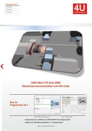
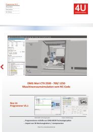
This is a multi-channel programming system for turning / milling machines with 3D machine room simulation. ● You create NC programs on the basis of an NC editor with machine macros and an integrated 2.5D CAD / CAM system. ● Templates are stored for different types of processing (bar / chuck ...). ● Program structures are generated automatically. ● The 3D machine space simulation shows the real machining process simultaneously. ● The actual implementation of the NC program is simulated. ● In the event of a collision, the relevant machine components and the associated NC blocks are displayed. What are the extensions of the V5.1 programmer? ● Project history and additional windows for further machine conditions ● Main and subprogram names are displayed in the simulation ● 3D blank (prismatic, rotationally symmetrical) is to be read in the STL format into the simulation ● The current workpiece is to be generated from the simulation as a 3D blank in the STL format ● Gaps can be measured in three dimensions ● NC block run times can be displayed as an EXCEL table
This is a multi-channel programming system for turning / milling machines with 3D machine room simulation.
● You create NC programs on the basis of an NC editor with machine macros and an integrated 2.5D CAD / CAM system.
● Templates are stored for different types of processing (bar / chuck ...).
● Program structures are generated automatically.
● The 3D machine space simulation shows the real machining process simultaneously.
● The actual implementation of the NC program is simulated.
● In the event of a collision, the relevant machine components and the associated NC blocks are displayed.
What are the extensions of the V5.1 programmer?
● Project history and additional windows for further machine conditions
● Main and subprogram names are displayed in the simulation
● 3D blank (prismatic, rotationally symmetrical) is to be read in the STL format into the simulation
● The current workpiece is to be generated from the simulation as a 3D blank in the STL format
● Gaps can be measured in three dimensions
● NC block run times can be displayed as an EXCEL table

You also want an ePaper? Increase the reach of your titles
YUMPU automatically turns print PDFs into web optimized ePapers that Google loves.
9 | G codes
9.2.1 Commands not supported (examples)
Memo
The following NC commands are not implemented. If required and technically feasible,
they can be implemented later (if required for specific machine models).
General commands:
ACN
Absolute dimensions for rotary axes, negative direction of rotation
ACP
Absolute dimensions for rotary axes, positive direction of rotation
AMIRROR
ANG
AP
AR
ASCALE
CASE
CHF
CHR
CIP
DC
DITE
DITS
FA
FFWOF
FGROUP
FL
FXS
MIRROR
P
POS
POSA
POSP
REPEAT
REPEATB
RND
RNDM
RP
MRP
SCALE
SETAL
SUPA
TOFRAME
TRAANG
TRAORI
TURN
WAITP
WAITS
Mirror image on the specified axis is not supported yet. The assignment
of MD10610 and MD 10612 is not clear.
Contour angle
Polar angle when programming with polar coordinates
Opening angle for arcs
Scaling of the specified axes
Branching
Length of chamfer for contours
Length of chamfer in direction of movement for contours
Circular interpolation via intermediate point
Absolute dimensions for rotary axes, shortest path
Thread run-out path
Thread run-in path
Axial feed
Pilot control OFF (by analogy, FFWON)
Feedrate value applies all axes specified
Limit speed for synchronous axes
Retraction from fixed stop ON (by analogy, FXST, FXSW)
Mirror image on the specified axis is not supported yet.
The assignment of MD10610 and MD 10612 is not clear.
Repetitive call of subroutines
Positioning of the specified axis (axes) without block advance
Positioning of the specified axis (axes) with block advance
Positioning of the specified axis (axes) via intermediate points
Repetitive execution of a specific part of the program
Repetitive execution of the specified block
Contour corner rounding
Contour corner rounding (modal)
Polar radius when programming with polar coordinates
Rotation of machining plane with ROT or AROT
Scaling of the specified axis (axes)
Setting an alarm
Disabling all zero offsets block by block
Frame generation after tool orientation
Transformation to inclined axis
three, four and five-axis transformation
Selection of additional circular passes for G2/G3
Waiting for end of traverse movement
Waiting for reaching the spindle position
9
127
G codes
A-D821UK-1_200420
127